
Related Manuals for araknis AN-100-SW-R-5


Summary of Contents for araknis AN-100-SW-R-5
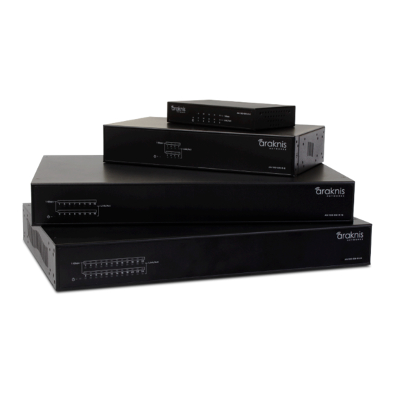
- Page 1 1 00 - SE R I E S NE T WO R K S W IT CH ES I ns ta ll a t io n Ma n u al Unmanaged AV Rack Network Switches...
-
Page 2: Certifications And Warnings
Only the AN-100-SW-R-8, AN-100-SW-R-16, and AN-100-SW-R-24 port switches have been evaluated by UL. The AN-100-SW-R-5 port switch has not been evaluated by UL. About This Manual This manual was created to provide a reference for installers and end users of Araknis Networks products. -
Page 3: Table Of Contents
1.3 Package Contents 1.4 Recommended for Installation 2. Installation 2.1 Basic Instructions 2.2 Switch Placement 2.2.1 General Guidelines 2.2.2 AN-100-SW-R-5 Placement Options 2.2.2.1 Shelf Mounting 2.2.2.2 On-Wall Mounting 2.2.3 AN-100-SW-R-8/16/24 Placement Options 2.2.3.1 Shelf Mounting 2.2.3.2 Rack Mounting 2.2.3.3 On-Wall Mounting 2.3. -
Page 4: Figures And Tables
Figure 2. AN-100-SW-R-8/16/24 Package Contents Figure 3. Single Switch Network Figure 4. Multiple Switches in Network Figure 5. AN-100-SW-R-5 Rubber Foot Installation Figure 6. AN-100-SW-R-5 On-Wall Mounting Figure 7. AN-100-SW-R-8/16/24 Rubber Foot Installation Figure 8. AN-100-SW-R-8/16/24 Rack Mounting Options Figure 9. -
Page 5: Introduction
Ethernet Ports PoE Ports SFP Ports Power Supply AN-100-SW-R-5 External AN-100-SW-R-8 Internal AN-100-SW-R-16 Internal AN-100-SW-R-24 Internal Only the AN-100-SW-R-8, AN-100-SW-R-16, and AN-100-SW-R-24 port switches have been evaluated by UL. The AN-100-SW-R-5 switch has not been evaluated by UL. www.araknisnetworks.com Support: 866.838.5052... -
Page 6: Features
Ethernet ports can be up to 1 Gbps simultaneously. Multiple Mounting Options In addition to industry-standard options for shelf- and rack-mounting, Araknis network switches are also capable of over a dozen possible custom rack positions, and even wall-mounting options, using only the accessories included in the box. -
Page 7: Package Contents
I NTR O DU C TI O N 1.3 — Figure 1. AN-100-SW-R-5 Package Contents Package Contents Screws (4) AN-100-SW-5 Gigabit Ethernet Switch (1) Wall Anchors (4) Quick Installation Guide (1) Rack Mount Kit (1) Rubber Feet (1) DC Power Supply (1) Figure 2. -
Page 8: Installation
Pro Tip: Having a record of the location, wire length, and connection path for each network device can save a lot of time and expense later. Take some time to record a summary of the network architecture before calling the job “done.” © 2013 Araknis Networks ®... -
Page 9: Figure 3. Single Switch Network
I NS TAL LATI O N Figure 3. Single Switch Network Example - 1 Desktop Server Printer/ Scanner AppleTV Phone Figure 4. Multiple Switches in Network Example - 2 Desktop Server Printer/ Scanner AppleTV Phone IP Surveillance IP Camera www.araknisnetworks.com Support: 866.838.5052... -
Page 10: Switch Placement
Switch Placement Note: Section 2.2.1 applies to all AN-100-SW-R models. Section 2.2.2 addresses all placement options for the AN-100-SW-R-5 port switch. Section 2.2.3 covers all placement options for the AN-100-SW-R 8/ -16,/ -24 models. Consider the following guidelines before choosing any location or mounting type for 2.2.1 —... -
Page 11: An-100-Sw-R-5 Placement Options
Then, place the switch in the desired position. Make sure the shelf or surface used is flat and stable. Figure 5. AN-100-SW-R-5 Rubber Foot Installation 2.2.2.2 On-Wall Mounting The switch may be mounted on a wall or any other surface by using the included mounting ears. -
Page 12: An-100-Sw-R-8/16/24 Placement Options
Locate the included rack-mounting ears and screws from the packaging and a #2 Philips screwdriver. Attach the ears to each side of the switch for the desired mounting angle as shown: Figure 8. AN-100-SW-R-8/16/24 Rack Mounting Options Front Rack Mounting Rear Rack Mounting © 2013 Araknis Networks ®... -
Page 13: Figure 9. An-100-Sw-R-8/16/24 Rack Mounting Procedure
I NS TAL LATI O N Figure 8. (continued) Multiple Mounting Options Standard Protruding Recessed After the ears are attached, mount the switch in the rack as shown below. Insert the bottom screws first to avoid bending the mounting ears or chassis. Figure 9. -
Page 14: On-Wall Mounting
After attaching the ears, mount the switch on the wall in the desired location as shown using drywall screws or fasteners suitable for the wall surface material (not included). For wall mounting, we recommend using 4 drywall screws, minimum of 1-1/4” X 8 GA with anchors © 2013 Araknis Networks ®... -
Page 15: Powering The An-100-Sw-R Switch
AC Electrical Input Voltage (AC Only) 100-240V AC, 50~60Hz Requirements The AN-100-SW-R-5 is designed with an external DC power supply that connects inline 2.3.2 — between the power outlet and the DC input on the switch. AN-100-SW-R-5 2.3.2.1 Power Plug Connection Figure 11. -
Page 16: Connecting Network Devices
Leave one switch port open to allow connection to the rest of the network. Connect a network cable from the switch to the device providing network connectivity. Power up all equipment and test each attached device for network connectivity. © 2013 Araknis Networks ®... -
Page 17: Product Layout
4 . PR OD UC T LAYOUT This section describes the hardware layout of the 100-series unmanaged network switch. Each connection, indicator, and control is summarized. 4.1 — Figure 14. Front Panel Layout Front Panel Layout 1 Gbps Link/Act Link/Act AN-100-SW-R-16 Table 4. -
Page 18: Side Layout
OFF 50-60Hz Ethernet Ports (RJ45) Connect Ethernet network cables routed to equipment. Master Power Switch Toggle Switch for master power control. Power Jack Attach an IEC power cable. Note: AN-100-SW-R-8 does NOT have a power switch. © 2013 Araknis Networks ®... -
Page 19: Specifications
5 . S PEC IF ICATIONS Table 7. Specifications Model AN-100-SW-R-5 AN-100-SW-R-8 AN-100-SW-R-16 AN-100-SW-R-24 Interface 10/100/1000Base RJ-45 Ports 1000Base SFP Ports PoE ports (In PoE Models) Physical Configuration Flash Memory SDRAM 64KB (SRAM) 64KB (SRAM) Packet Buffer 128KB 512KB Performance... -
Page 20: Appendix
Make sure that ventilation is adequate. Overheating can cause the unit to shut down for self-protection. Change out the power cord or supply with another of the same type, and test again. The power supply or cable may be damaged or defective. © 2013 Araknis Networks ®... -
Page 21: Warranty
6.2. — Warranty year 2 Year Limited Warranty Araknis Networks products have a 2-Year Limited Warranty. This warranty includes parts ® and labor repairs on all components found to be defective in material or workmanship under normal conditions of use. This warranty shall not apply to products which have been abused, modified or disassembled. - Page 22 © 2013 Araknis Networks ® 131028-1738...
Need help?
Do you have a question about the AN-100-SW-R-5 and is the answer not in the manual?
Questions and answers