Table of Contents
Advertisement
Advertisement
Table of Contents

Related Manuals for araknis AN-300-SW-F/R-8


Summary of Contents for araknis AN-300-SW-F/R-8
- Page 1 300 – SERIES NETWORK SWITCHES Product Manual Managed AV Rack Network Switches...
-
Page 2: About This Manual
About This Manual This manual was created to provide a reference for installers and end users of Araknis Networks products. It provides all known information regarding the installation, setup, use, and maintenance of the product. This manual was created expressly for electronic use, but has been formatted so that it may be printed and bound using either one-sided or front-and-back printing. -
Page 3: Table Of Contents
TABLE OF CONTENTS About This Manual ....................................2 Figures ......................................... 6 Tables ........................................7 1—Introduction ......................................8 ® 1.1— Welcome to Araknis Networks ............................... 8 ® 1.1.1—Araknis 300-Series Overview ............................ 8 1.2— Package Contents ..................................9 1.3— Recommended for Installation ..............................9 2—Installation ...................................... - Page 4 4.7.1.3— Configuring SNMPv3 Users ........................78 4.7.1.4— Configuring SNMPv3 Groups ......................... 79 4.7.1.5— Configuring SNMPv3 Views ........................80 4.7.1.6— Configuring SNMPv3 Group Access Rights ..................81 4.7.2—Access Management ..............................82 4.7.2.1— Configuring Security ..........................82 ® © 2014 Araknis Networks...
- Page 5 4.7.2.2— Configuring User Accounts ........................83 4.7.2.3— Configuring SSH ............................. 84 4.7.2.4— Filtering IP Addresses For Management Access ................. 84 4.7.3—DHCP Snooping ................................. 86 4.7.3.1— DHCP Snooping Port Statistics ......................86 4.7.3.2— DHCP Snooping Configuration ......................87 4.7.4—Configuring Loop Protection ............................88 4.7.4.1—...
-
Page 6: Figures
STP Statistics ....................65 Figure 57. STP Bridge Configuration ................. 66 Figure 58. STP CIST Port Configuration................68 Figure 59. MAC-based VLAN ..................... 70 Figure 60. MAC-based VLANs Status ................70 Figure 61. MAC-Based VLAN Configuration ..............71 ® © 2014 Araknis Networks... -
Page 7: Tables
Figure 62. Private VLANs ....................72 Figure 63. Port Isolation Settings ..................73 Figure 64. SNMP Configuration Page ................74 Figure 65. SNMP Configuration..................75 Figure 66. SNMPv3 Community Access Strings ............... 77 Figure 67. SNMPv3 User Configuration ................78 Figure 68. -
Page 8: 1-Introduction
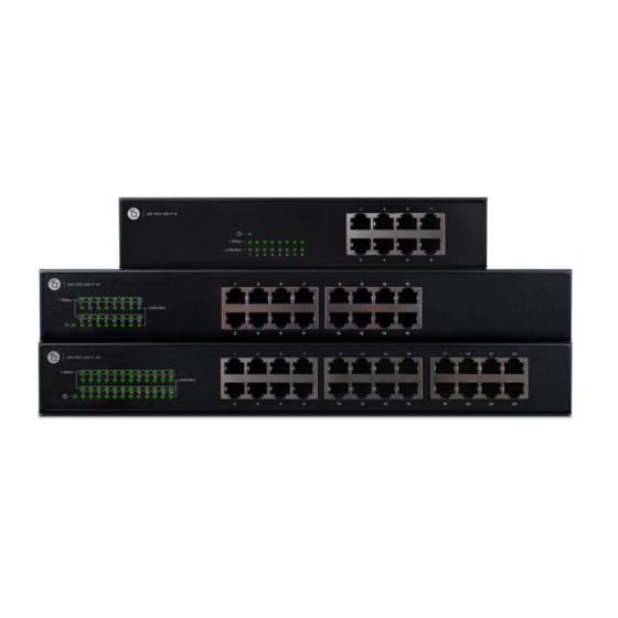
1— INTRODUCTION ® 1.1— Thank you for choosing an Araknis 300-series Network Switch. The 300-series managed network switch is an enterprise-class switch specifically designed for use in Ethernet Welcome to applications within the residential market. Araknis Networks ® With front-facing indicators and rear-facing ports, the 300-series switch was designed for easy installation and high performance in an environment where traffic on the network and the number of users could increase continuously. -
Page 9: Package Contents
1.2— Figure 1. Package Contents Package Contents 1.3— #2 Phillips screwdriver (for mounting ear installation) Recommended for Screws and anchors for wall-mount installation optional; use a material that is fastener rated, specified for use in the wall, and can safely hold the weight of the model in use Installation ... -
Page 10: 2-Installation
Mounting Options 2.1.1— Figure 2. Rack Mounting Ears Rack Mounting Note — All product pictures in this manual feature AN-300-SW-R models as an example of the 300-series product line. Front-facing models are identical in operation. ® © 2014 Araknis Networks... -
Page 11: Rack Mounting Guidelines
Figure 3. Rack Mounting Options 2.1.1.1— Elevated Operating Ambient – If installed in a closed or multi-unit rack assembly, the Rack Mounting operating ambient temperature of the rack environment may be greater than room ambient. Therefore, consideration should be given to installing the equipment in an environment Guidelines compatible with the maximum ambient temperature of 104°F. -
Page 12: 2-Wall Mounting
Shelf Mounting Warning! — Caution: Do not stack more than 4 switches together. Do not stack any other equipment on top of the network switch to avoid possible interference or damage. Figure 5. Shelf Mounting ® © 2014 Araknis Networks... -
Page 13: Front Panel Layout
2.2— Figure 6. Front Panel Layout Front Panel Layout 2.3— Figure 7. Rear Panel Layout Rear Panel Layout 1. Ethernet Ports (RJ45) — Connect Ethernet network cables routed to equipment. 2. SFP Ports — Port for AN-ACC-SFP-E-100 or AN-ACC-SFP-MMF-350 3. Master Power Switch — Toggle Switch for master power control. 4. -
Page 14: Side Panel Layout
2. Rack Mounting Holes — The combination of threaded holes at the front and rear of each side allow for many variations in mounting options. Note — The PoE model shown above is for model AN-300-SW-R-24-POE. 8-port and 16-port models only have one fan. ® © 2014 Araknis Networks... -
Page 15: Installation Diagram
2.5— Figure 10. Installation Diagram Installation Diagram 2.6— Figure 11. Power Inlet Powering the Switch Table 2. Power Requirements Input Voltage (AC Only) 100~240V AC, 50~60Hz www.snapav.com Support: 866.838.5052... -
Page 16: 3-Software Configuration
Multiple Spanning Trees (MSTP) Algorithm Up to 4K using IEEE 802.1Q, port-based VLANs Virtual LANs Supports Differentiated Services (DiffServ) and DSCP remarking Quality of Service Supports IGMP snooping and query, and Multicast VLAN Multicast Filtering Registration ® © 2014 Araknis Networks... -
Page 17: Description Of Software Features
You can fully backup the settings for this switch to a file on your PC. Once this is done, you ® have the ability to load this file back into the same switch or deploy it to another Araknis 300- series switch. - Page 18 You have the ability to assign Multicast traffic to its own VLAN so that it will not interfere with normal network traffic. Setting the required priority level for the designated VLAN guarantees real-time delivery. IGMP Snooping and Query are used to manage multicast group registration for IPv4 traffic. ® © 2014 Araknis Networks...
-
Page 19: System Defaults
System Defaults Management on page 47 for information about using configuration files and restoring the switch to factory default settings.) Table 4. System Defaults Function Parameter Default Setting “araknis” Authentication Admin User Name “araknis” Admin Password HTTPS Enabled Enabled Port Security... - Page 20 IP Address 192.168.20.254 Subnet Mask 255.255.255.0 Default Gateway 0.0.0.0 DHCP Client: Disabled Snooping: Disabled Proxy service: Disabled Multicast Filtering IGMP Snooping Snooping: Disabled Querier: Disabled Multicast VLAN Registration Disabled System Log Status Enabled Clock Synchronization Disabled ® © 2014 Araknis Networks...
-
Page 21: Device Access Methods And Guidelines
3.4— Device Access Methods and Guidelines 3.4.1— This section details how to connect to the switch through the web interface. To make the best use of the management features in your switch, it is highly recommended to configure it with an Web Interface IP address in the same range as other equipment on the local network before permanently installing the switch. - Page 22 C. On the left panel, click on “Change Adapter Settings”. D. Right click on the local Ethernet adapter icon and click on “Properties”. E. Click to highlight “Internet Protocol Version 4 (TCP/IPv4), then click “Properties”. ® © 2014 Araknis Networks...
- Page 23 If you do not see the login page, repeat step 3. 7. Enter “araknis” for both the user name and password fields and then click the “Login” button. 8. From the menu, click SETTINGS->System. To request an address from a local DHCP Server, mark the DHCP Enabled check box.
-
Page 24: Navigating The Web Browser Interface
3.5— A username and password must be entered to access the web-browser interface. The default administrator user name and password is “araknis” for both fields. The administrator has Navigating the Read/Write access to all configuration parameters and statistics. Web Browser Interface 3.5.1—... -
Page 25: 2-Navigation Menu Overview
3.5.2— Basic configuration items in the menu are always visible. The Advanced menu is collapsed by default. Click “Advanced” to expand all Advanced settings. Navigation Menu Overview Table 5. below briefly describes the selections available on the 300-series switch. 3.5.2.1— Table 5. -
Page 26: Status Menu
Device Gateway – Management VLAN default gateway. MAC Address – Device Media Access Control (MAC) address. ® Service Tag – Araknis Networks unique device identifier. Used to track individual devices for easy service and support. Firmware Version – Current running firmware version. -
Page 27: Port Status And Panel Display
3.6.1.2— The System Status page displays a live graphic of the switch with the current status of each Port Status and Panel port. Clicking on the image of a port opens the Advanced Port Statistics page of that port (4.1.1— Display Port Statistics on page 51) Below the graphic, the Port Status table summarizes the Port, Name, Link Speed, Duplex... -
Page 28: Events Log
Parameters Level — Shows the level of the log message. Options include Info, Warning, and Error. Time — Time stamp of the log entry. Message — Summary of the event log entry. ® © 2014 Araknis Networks... -
Page 29: 2-Ports
3.6.2— Use the Port Status table to display a summary of basic information on each port. Ports Figure 17. Ports Status Page Parameters The following parameters are displayed: Port – The number of the port. Name – The assigned name of the port. ... -
Page 30: Settings Menu
Changing the System characters) Name Figure 19. System Name Path Settings, System Configuration Instructions To configure System Name: 1. Click Settings, System. 2. Enter the new name in the System Name field. 3. Click Apply. ® © 2014 Araknis Networks... -
Page 31: Changing The Ip Address And Network Access Settings
3.7.1.2— The system settings section can be used to configure the IP address of the switch. The IP Changing the IP address for the switch can be obtained via DHCP or configured manually. To manually configure an IP address, you need to change the switch's default settings to values that are Address and Network compatible with your network. -
Page 32: Changing Admin Username And Password
Figure 21. Administrator Credentials Password Path Settings, System, System Settings Administrator Username – Change the default username of the admin (default: araknis). Parameters Administrator Password – Change the default password for the admin account (default: araknis). Configuration Instructions To change Admin Username and Password: 1. -
Page 33: Configuring Time Settings
3.7.1.4— Use the Time Settings section to specify the Network Time Protocol (NTP) servers to query for Configuring Time the current time. NTP allows the switch to set its internal clock based on periodic updates from an NTP time server. Recording meaningful dates and times in the event log is essential for Settings troubleshooting the switch and maintaining the system time will ensure that this log is correct. -
Page 34: Configuring Snmp System And Trap Settings
SNMP. Trap messages can also be enabled but you first must enable the trap function and have a destination host specified before it will actually issue a message. ® © 2014 Araknis Networks... -
Page 35: Figure 23. Snmp Configuration
Settings, System, Advanced Settings Figure 23. SNMP Configuration Parameters SNMP System Configuration: Enable SNMP — Enables or disables SNMP service. (Default: Enabled – SNMP v2c) SNMP Read Community — The community used for read-only access to the SNMP agent. -
Page 36: Configuring Dhcp Relay And Option 82 Information
1. Click Settings, System. 2. Enable the DHCP relay function, specify the DHCP server’s IP address, enable Option 82 information mode, and set the method by which to handle relay information found in client packets. 3. Click Apply. ® © 2014 Araknis Networks... -
Page 37: Configuring Upnp
3.7.1.7— Universal Plug and Play (UPnP) is a set of protocols that allows devices to connect seamlessly, Configuring UPnP and simplifies the deployment of home and office networks. When a device is added to the network, the UPnP discovery protocol allows that device to broadcast its services to other UPnP devices on the network. -
Page 38: 2-Ports
Configuration Instructions To configure port connection settings: 1. Click Settings, Ports. 2. Make any required changes to the connection settings. 3. Click Apply. ® © 2014 Araknis Networks... -
Page 39: 3-Power Over Ethernet (For Poe Models Only)
3.7.3— Use the Power over Ethernet (PoE) Settings page to check Power Consumption on each port (as well as the entire system). Set Maximum Power Allocation for each port, shut down power Power over Ethernet on individual ports, power cycle individual or multiple ports, and set power allocation priority. If (for PoE Models Only) the power demand from devices connected to the switch exceeds the power budget, the switch uses port PoE Priority settings to limit the supplied power. -
Page 40: Figure 28. Poe Settings
Maximum Allocated Power. Configuration Instructions To configure port-specific PoE settings: 1. Click Settings, PoE. 2. Specify the port maximum power allocation and priority. 3. Click Apply. ® © 2014 Araknis Networks... -
Page 41: 4-Vlans
3.7.4— The Virtual Local Area Network (VLAN) technology allows you to divide physical ports to different logical groups. Each group is a virtual LAN, the clients within the VLAN are a VLANs broadcast domain. If clients in different VLANs need to communicate, connect the VLAN to an additional upper router (or a L3 device). -
Page 42: Creating New Vlans
2. Change the ports assigned to the default VLAN (VLAN 1) if required. 3. To configure a new VLAN, click New VLAN, enter the VLAN ID, the VLAN name, and then mark the ports to be assigned to the new group. 4. Click Apply. ® © 2014 Araknis Networks... -
Page 43: Configuring Vlan Attributes For Port Members
3.7.4.2— Use the Advanced Settings section to configure VLAN attributes for specific ports, including Configuring VLAN enabling ingress filtering, setting the accepted frame types, and configuring the default VLAN identifier (PVID). Attributes For Port Members VLAN Settings — Configuring Attributes Figure 31. - Page 44 Tag_all — All VLANs are tagged. Untag_all — All VLANs are untagged. Configuration Instructions To configure attributes for VLAN port members: 1. Click Settings, VLANs. 2. Configure in the required settings for each interface. 3. Click Apply. ® © 2014 Araknis Networks...
-
Page 45: 5-Link Aggregation
3.7.5— Link Aggregation is also known as Port Trunking. It allows using multiple ports in parallel to increase the link speed between two switches to increase the redundancy for higher Link Aggregation availability. The switch supports both static trunking and dynamic Link Aggregation Control Protocol (LACP). -
Page 46: Maintenance Menu
After you press Start, five ICMP packets are transmitted, and the sequence number and round- trip time are displayed upon reception of a reply. The page refreshes automatically until responses to all packets are received, or until a timeout occurs. ® © 2014 Araknis Networks... -
Page 47: 2-File Management
3.8.2— Use the File Management Page to make backups of your configuration, load configuration files, and manage firmware updates and versions. File Management Figure 35. File Management Page 3.8.2.1— Use the Back Current Configuration option to save the current configuration settings to a file on Saving Configuration your local management station. -
Page 48: Restoring Factory Defaults
2. Power the switch off, wait a couple of seconds and then power switch back on. 3. Wait until the activity lights activate on Ports 1 and 2, then remove the Ethernet cable. 4. Restart the setup process. ® © 2014 Araknis Networks... -
Page 49: Activating A Secondary Firmware
The firmware version and date information may be empty for older firmware releases. This does not constitute an error. 3.8.2.6— Use the Firmware section to upgrade the switch’s system firmware using a file provided by ® Upgrading Firmware Araknis Networks. Figure 38. Firmware Update Path Maintenance, File Management, Software Image Caution! —... -
Page 50: 3-Restart Device
Figure 39. Restart Device Path Maintenance, Restart Device Configuration Instructions To restart the switch: 1. Click Maintenance, Restart Device. 2. Click Yes. 3. The restart is complete when the user interface displays the login page again. ® © 2014 Araknis Networks... -
Page 51: 4-Advanced Configuration
4— ADVANCED CONFIGURATION 4.1— The Advanced Ports menu has two sub-menus: Ports Statistics and Port Settings. Use Port Statistics page to view detailed counters for each port. Use Port Settings to view advanced Ports features for each port on the switch such as Maximum Frame Size. 4.1.1—... -
Page 52: 2-Configuring Advanced Port Settings
Discard — Discards a frame after 16 collisions (default). Restart — Restarts the back-off algorithm after 16 collisions. Flow Control — Flow control can eliminate frame loss by “blocking” traffic from end ® © 2014 Araknis Networks... - Page 53 devices or other network devices connected directly to the switch when the buffer is overloaded on a specific switch port. When enabled, back pressure is used for half duplex operation and IEEE 802.3-2005 (formally IEEE 802.3x) for full duplex operation. (Default: Disabled) When auto-negotiation is used (enabled by default), this parameter indicates the flow control capability advertised to the connected device.
-
Page 54: Lacp
A trunk formed with another switch using LACP will automatically be assigned the next available trunk ID. All ports on both ends of an LACP trunk must be configured for full duplex, either manually ® © 2014 Araknis Networks... - Page 55 or auto-negotiation. Ports assigned to a common link aggregation group (LAG) must meet the following criteria: Ports must have the same LACP Admin Key. Using Auto option of the Admin Key will avoid this problem. One of the ports at either the near end or far end must be set to active initiation mode. www.snapav.com Support: 866.838.5052...
-
Page 56: Connected Devices
VLAN – The VLAN containing this entry. MAC Address – Physical address associated with this interface. Port Members – The ports associated with this entry. ® © 2014 Araknis Networks... -
Page 57: Igmp Snooping
4.4— Multicasting is used to support real-time applications like control systems or streaming audio. Using multicast, a server does not have to establish individual connections with each target IGMP Snooping client. The server broadcasts its service to the network, and any client that wants to receive the multicast stream simply subscribes to the multicast service with their connected switch. -
Page 58: 1-Igmp Snooping Statistics
Figure 46. IGMP Snooping Ports Path Advanced, IGMP Snooping Port – Port Identifier. Parameters Status – Ports connected to multicast servers may be dynamically discovered or statically assigned to a port on this switch. ® © 2014 Araknis Networks... -
Page 59: 3-Configuring Global Settings For Igmp Snooping
4.4.3— Use the IGMP Snooping Configuration table to configure global settings that control the forwarding of multicast traffic. When enabled, the switch forwards traffic only to the ports that Configuring Global request multicast traffic as opposed to the switch broadcasting the traffic to all ports and Settings for IGMP possibly disrupting network performance. -
Page 60: 4-Configuring Port Related Settings For Igmp Snooping
When the maximum number of groups is reached on a port, any new IGMP join reports will be dropped. (Range: 1-10; Default: unlimited) Configuration Instructions To configure global and port-related settings for IGMP Snooping: 1. Click Advanced, IGMP Snooping. 2. Adjust the IGMP settings as required. 3. Click Apply. ® © 2014 Araknis Networks... -
Page 61: 5-Showing Igmp Snooping Group Information
4.4.5— Use the IGMP Snooping Group Information section to display the port members of each service group. Showing IGMP Snooping Group Figure 49. IGMP Snooping Group Information Information Path Advanced, IGMP Snooping Parameters These parameters are displayed: VLAN ID – VLAN Identifier. ... -
Page 62: Showing Igmp Ssm Information
Source Address – IP Address of the source. Currently, the system limits the total number of IP source addresses for filtering to 128. Different source addresses belonging to the same group are treated as single entry. Type –May be set to either Allow or Deny. ® © 2014 Araknis Networks... -
Page 63: Spanning Tree
4.5— The Spanning Tree Protocol (STP) can be used to detect and eliminate network loops. This allows the switch to communicate with other switches in the network to ensure only one route Spanning Tree exists between any two end devices, and provide backup routes which automatically take over when a primary route goes down. -
Page 64: 1-Status
Topology Flag – The current state of the Topology Change Notification flag (TCN) for this bridge instance. Topology Change Last – Time since the Spanning Tree Algorithm was last performed. Uptime – The time since the bridge port was last initialized. ® © 2014 Araknis Networks... -
Page 65: Stp Port Status
4.5.1.2— Use the Port Status section to display the STP functional status of participating ports. STP Port Status Figure 55. STP Port Status Path Advanced, Spanning Tree, Status Port – Port Identifier. Parameters CIST Role – Port roles can be either: a part of the active topology connecting to the root bridge (i.e., root port), connecting a LAN segment through the switch to the root bridge (i.e., designated port), or is an alternate or backup port that may provide connectivity if the Spanning Tree topology changes. -
Page 66: 2-Stp Bridge Settings
“interfaces,” which includes both ports and trunks.) Minimum — The higher of 6 or [2 x (Hello Time + 1)] Maximum — The lower of 40 or [2 x (Forward Delay - 1)] Default — 20 ® © 2014 Araknis Networks... - Page 67 Transmit Hold Count — The number of BPDU's a bridge port can send per second. When exceeded, transmission of the next BPDU will be delayed. (Range: 1-10; Default: 6) Max Hop Count — The maximum number of hops allowed in the MST region before a BPDU is discarded.
-
Page 68: 3-Cist Ports
This feature is also known as Root Guard. BPDU Guard – This feature can prevent loops by shutting down a port when a BPDU is received instead of putting it into the spanning tree discarding state. ® © 2014 Araknis Networks... - Page 69 (Default: Disabled) Point-to-Point – Transition to the forwarding state is faster for point-to-point links than for shared media. Available options include: Auto – The switch automatically determines if the interface is attached to a point-to- point link or to shared medium (Default). •...
-
Page 70: Advanced Vlans
MAC Address – A source MAC address that is mapped to a specific VLAN. VLAN ID – VLAN to which ingress traffic matching the specified source MAC address is forwarded. Port Members – The ports assigned to this VLAN. ® © 2014 Araknis Networks... -
Page 71: Configuring Mac-Based Vlans
4.6.1.2— When MAC-based VLAN classification is enabled, untagged frames received by a port are Configuring MAC- assigned to the VLAN, which is mapped to the frame’s source MAC address. When no MAC address is matched, untagged frames are assigned to the receiving port’s native Port VLAN ID based VLANs (PVID). -
Page 72: 2-Private Vlans
To configure VLAN port members for private VLANs: 1. Click Advanced, VLANs, Private VLANs. 2. Add or delete members of any existing PVLAN, or click Add New Private VLAN and mark the port members. 3. Click Apply. ® © 2014 Araknis Networks... -
Page 73: Using Port Isolation
4.6.2.2— An isolated port cannot forward any unicast, multicast, or broadcast traffic to any other ports in Using Port Isolation the same PVLAN. Ports within a private VLAN (PVLAN) are isolated from other ports that are not in the same PVLAN. Port Isolation can be used to block communications between ports within the same PVLAN. -
Page 74: Security
These community strings are used for authentication. SNMPv3 provides additional security features that cover message integrity, authentication, and encryption; as well as controlling user access to specific objects in the MIB. Figure 64. SNMP Configuration Page ® © 2014 Araknis Networks... -
Page 75: Configuring Snmp System And Trap Settings
4.7.1.1— To manage the switch through SNMP, you must first enable the protocol and configure basic Configuring SNMP access parameters. To issue trap messages, the trap function must be enabled, and the destination host specified. System and Trap Settings Figure 65. SNMP Configuration Path Advanced, Security, SNMP... - Page 76 SNMPv3 traps or informs are enabled. Note — To be able to select a name from this field, enter an SNMPv3 user with the same Trap Security Engine ID in the SNMPv3 Users Configuration section. ® © 2014 Araknis Networks...
-
Page 77: Setting Snmpv3 Community Access Strings
4.7.1.2— Use the SNMPv3 Community Configuration page to set community access strings. All Setting SNMPv3 community strings used to authorize access by SNMP v1 and v2c clients should be listed in the SNMPv3 Communities Configuration table. For security reasons, you should consider removing Community Access the default strings. -
Page 78: Configuring Snmpv3 Users
2. Click “Add new user” to configure a user name. 3. Enter a remote Engine ID of up to 64 hexadecimal characters. 4. Define the user name, security level, authentication, and privacy settings. 5. Click Apply. ® © 2014 Araknis Networks... -
Page 79: Configuring Snmpv3 Groups
4.7.1.4— Use the SNMPv3 Group Configuration table to configure SNMPv3 groups. An SNMPv3 group Configuring SNMPv3 defines the access policy for assigned users. You can use the pre-defined default groups, or create a new group and the views authorized for that group. Groups Figure 68. -
Page 80: Configuring Snmpv3 Views
Configuration Instructions To configure SNMPv3 views: 1. Click Advanced, Security, SNMP. 2. Click “Add new view” to set up a new view. 3. Enter the view name, view type, and OID subtree. 4. Click Apply. ® © 2014 Araknis Networks... -
Page 81: Configuring Snmpv3 Group Access Rights
4.7.1.6— Use the SNMPv3 Access Configuration page to assign portions of the MIB tree to which each Configuring SNMPv3 SNMPv3 group is granted access. You can assign more than one view to a group to specify access to different portions of the MIB tree. Group Access Rights Figure 70. -
Page 82: 2-Access Management
Management access to the switch can be controlled through local authentication of user names and passwords stored on the switch. Additional authentication methods include Secure Shell (SSH), Secure Hypertext Transfer Protocol (HTTPS) over the Secure Socket Layer (SSL), static configuration of client addresses, and SNMP. ® © 2014 Araknis Networks... -
Page 83: Configuring User Accounts
Advanced Menu – Admin access to the switch. Note – The default administrator name is “araknis” with the password “araknis”. It is highly recommended to assign a new administrator password as soon as possible, and store it in a safe place. -
Page 84: Configuring Ssh
HTTP/HTTPS – Filters IP addresses for access to the web interface over standard HTTP, or over HTTPS, which uses the Secure Socket Layer (SSL) protocol to provide an encrypted connection. SNMP – Filters IP addresses for access through SNMP. ® © 2014 Araknis Networks... - Page 85 TELNET/SSH – Filters IP addresses for access through Telnet, or through Secure Shell, which provides authentication and encryption. Configuration Instructions To configure addresses allowed access to management interfaces on the switch: 1. Click Advanced, Security, Access Management. 2. Click “New Entry”. 3.
-
Page 86: 3-Dhcp Snooping
Rx/Tx Lease Unknown – The number of lease unknown (option 53 with value 12) packets received and sent. Rx/Tx Lease Active – The number of lease active (option 53 with value 13) packets received and sent. ® © 2014 Araknis Networks... -
Page 87: Dhcp Snooping Configuration
4.7.3.2— Use the DHCP Snooping Configuration menu to filter IP traffic on insecure ports for which the DHCP Snooping source address cannot be identified via DHCP snooping. The addresses assigned to DHCP clients on insecure ports can be carefully controlled using the dynamic bindings registered with Configuration DHCP Snooping. -
Page 88: 4-Configuring Loop Protection
3. Enable loop protection for the port to be monitored, set the behavior to take if a loop is detected, and select whether or not the port will actively transmit control frames. 4. Click Apply. ® © 2014 Araknis Networks... -
Page 89: Loop Protection-Port Configuration
4.7.4.2— Figure 78. Port Loop Protection Menu Loop Protection-Port Configuration Path Advanced Configuration, Loop Protection Port – Port Identifier. Parameters Enable – Enables loopback detection on a port. (Default: Enabled) Action – Select the action to take when a loop is detected on a port. (Options: Shutdown Port, Shutdown Port and Log, Log Only) ... -
Page 90: 5-Port Mirroring
1. Click Advanced, Security, Port Mirroring. 2. Select the destination port to which all mirrored traffic will be sent. 3. Set the mirror mode on any of the source ports to be monitored. 4. Click Apply. ® © 2014 Araknis Networks... -
Page 91: Advanced Qos
4.8— Quality of service (QoS) is the overall performance of a network, particularly the performance seen by the users of the network. This is usually measured by several related aspects of the Advanced QoS network service, such as error rates, bandwidth, throughput, transmission delay, availability, jitter, etc. -
Page 92: 1-Port Classification
1. Click Configuration, QoS, Port Classification. 2. Set any of the ingress port QoS classification parameters. To change tag class parameters, click “Disabled” to enter the QoS Ingress Port Tag Classification submenu. 3. Click Apply. ® © 2014 Araknis Networks... -
Page 93: 2-Port Policing
4.8.2— This page allows you to configure the Policer settings for all switch ports. Port Policing Figure 82. QoS Ingress Port Policers page Path Advanced, Advanced QoS, Port Policing Port — The port number for which the configuration below applies. Parameters ... -
Page 94: Figure 83. Qos Egress Port Schedulers Page
QoS Egress Port Scheduler and Shapers — Weighted Mode Figure 85. Path Advanced, Advanced QoS, Port Scheduler Parameters Port – Port identifier. Click the port number to access advanced scheduling and shaping for the port. (see below) ® © 2014 Araknis Networks... - Page 95 Mode – Shows the scheduling mode for this port. Weight – Shows the weight of each egress queue used by the port. On the QoS Egress Port Scheduler and Shapers page for each port (____below): Scheduler Mode – The switch can be set to service the queues based on a strict rule that requires all traffic in a higher priority queue to be processed before the lower priority queues are serviced, or Deficit Weighted Round-Robin (DWRR) queuing which specifies a scheduling weight for each queue.
-
Page 96: 3-Port Scheduler
To show an overview of the rate for each queue and port: 1. Click Advanced, Advanced QoS, Port Shaper. 2. Click on any entry under the Port field to configure the Port Scheduler and Shaper. See section 4.8.3—Port Scheduler on page 94. ® © 2014 Araknis Networks... -
Page 97: Port Tag Remarking
4.8.3.2— Port Tag Use the QoS Egress Port Tag Remarking page to show an overview of QoS Egress Port Tag Remarking Remarking mode. Click on any of the entries in the Port field to configure the remarking mode using classified PCP/DEI values, default PCP/DEI values, or mapped versions of QoS class and drop priority. - Page 98 1. Click Advanced, Advanced QoS, Port Tag Remarking. 2. Click on any entry under the Port field to configure the Port Tag Remarking mode. 3. Set the tag remarking mode and any parameters associated with the selected mode. 4. Click Apply. ® © 2014 Araknis Networks...
-
Page 99: Port Dscp
4.8.3.3— Port DSCP Use the QoS Port DSCP Configuration page to configure ingress translation and classification settings and egress rewriting of DSCP values. Figure 91. QoS Port DSCP Configuration Path Advanced, Advanced QoS, Port DSCP Port – Port identifier. Parameters ... -
Page 100: Dscp-Based Qos
To configure DSCP-based QoS ingress classification settings: 1. Click Advanced, Advance QoS, DSCP-Based QoS. 2. Specify whether the DSCP value is trusted, and set the corresponding QoS value and DP level used for ingress processing. 3. Click Apply. ® © 2014 Araknis Networks... -
Page 101: Dscp Translation
4.8.3.5— DSCP Translation Use the DSCP Translation page to configure DSCP translation for ingress traffic or DSCP re- mapping for egress traffic. Figure 93. DSCP Translation Table Path Advanced, Advanced QoS, DSCP Translation DSCP – DSCP value. (Range: 0-63) Parameters ... -
Page 102: Dscp Classification
To map DSCP values to a QoS class and drop precedence level. 1. Click Advanced, Advanced QoS, DSCP Classification. 2. Map key DSCP values to a corresponding QoS class and drop precedence level. 3. Click Apply. ® © 2014 Araknis Networks... -
Page 103: Qos Control List
4.8.3.7— QoS Control List Use the QoS Control List Configuration menu to configure Quality of Service policies for handling ingress packets based on Ethernet type, VLAN ID, TCP/UDP port, DSCP, ToS, or VLAN priority tag. Once a QCE is mapped to a port, traffic matching the first entry in the QoS Control List is assigned to the QoS class, drop precedence level, and DSCP value defined by that entry. - Page 104 Dport – Destination TCP/UDP port. (Any, Specific/Range: 0-65535) Action Parameters Action – Indicates the classification action taken on ingress frame if the configured parameters are matched in the frame's content. If a frame matches the QCE, the following ® © 2014 Araknis Networks...
- Page 105 actions will be taken: Class (Classified QoS Class) – If a frame matches the QCE, it will be put in the queue corresponding to the specified QoS class, or placed in a queue based on basic classification rules. (Options: 0-7, Default (use basic classification); Default setting: 0) ...
-
Page 106: Storm Control
3. Select the control rate as a function of 2n pps (i.e., a value with no suffix for the unit of measure) or a rate in Kpps (i.e., a value marked with the suffix “K”). 4. Click Apply. ® © 2014 Araknis Networks... -
Page 107: 5-Specifications
5— SPECIFICATIONS 300 Series Non-PoE Managed Switch Specifications Model — AN-300-SW-F/R-8 AN-300-SW-F/R-16 AN-300-SW-F/R-24 Interface 10/100/1000Base RJ-45 Ports 1000Base SFP Ports PoE Ports Physical Configuration Flash Memory 16MB SPI SDRAM 128MB Packet Buffer 512KB Performance MAC Address Table Switching Capacity 20Gbps... - Page 108 1.7 x 12.9 x 8.2 1.7 x 17.2 x 8.6 Power Supply 100-240V AC, 50/60 Hz Maximum Power Consumption for System (W) Operating Temperature (°F) 32 - 104°F Humidity (non-condensing) 10 - 90% Weight (lbs.) Certification FCC Class A ® © 2014 Araknis Networks...
- Page 109 300 Series PoE Managed Switch Specifications Model AN-300-SW-F/R-8-POE AN-300-SW-F/R-16-POE AN-300-SW-F/R-24-POE Interface 10/100/1000Base RJ-45 Ports Ports 1000Base SFP PoE Ports Physical Configuration Flash Memory 16MB SPI SDRAM 128MB Packet Buffer 512KB Performance MAC Address Table Switching Capacity 20Gbps 36Gbps 52Gbps Forwarding Rate 14.8Mpps...
- Page 110 1.7 x 12.9 x 8.2 1.7 x 17.2 x 8.6 Power Supply 100-240V AC, 50/60 Hz Maximum Power Consumption for System (W) Operating Temperature (°F) 32 - 104°F Humidity (non-condensing) 10 - 90% Weight (lbs.) Certifications FCC Class A ® © 2014 Araknis Networks...
-
Page 111: Contacting Technical Support
Warranty 2-Year Limited Warranty ® Araknis Networks products have a 2-Year Limited Warranty. This warranty includes parts and labor repairs on all components found to be defective in material or workmanship under normal conditions of use. This warranty shall not apply to products that have been abused, modified or disassembled. - Page 112 141030-1230 ® © 2014 Araknis Networks...
Need help?
Do you have a question about the AN-300-SW-F/R-8 and is the answer not in the manual?
Questions and answers
system date is correct but how do I get this date applied to the video screens?
To apply the correct system date on the Araknis AN-300-SW-F/R-8, follow these steps:
1. Enable the NTP client (disabled by default).
2. Select a server from the preconfigured list or enter a custom NTP server address.
3. Ensure the device has a Default Gateway configured for NTP to work.
4. Optionally, manually set the time in the format “YYYY:MM:DD:HH:MM:SS” or click "Sync Time" to pull time from your PC.
5. Set the correct Time Zone based on the switch’s location.
6. Configure Daylight Savings Time as Disabled, Automatic (for U.S. rules), or Manual (for custom DST start/end dates).
These steps ensure the switch displays the correct system date.
This answer is automatically generated