
Subscribe to Our Youtube Channel
Related Manuals for Firepower TIG 140 AC/DC


Summary of Contents for Firepower TIG 140 AC/DC
- Page 1 FIREPOWER TIG 140 AC/DC Operating Manual English Canadien Français Americas Español Revision: AA Issue Date: August 8, 2014 Manual No.: 0-5355 3163339 www.firepower.com...
- Page 2 WE APPRECIATE YOUR BUSINESS! Congratulations on receiving your new Firepower product. We are proud to have you as our customer and will strive to provide you with the best service and support in the industry. This product is backed by our extensive warranty and world-wide service network.
- Page 3 While the information contained in this Manual represents the Manufacturer’s best judgement, the Manufacturer assumes no liability for its use. Welding Power Supply Operating Manual Number 0-5355 for: FIREPOWER TIG 140 AC/DC, Power Supply Only Part Number 1442-0031 FIREPOWER TIG 140 AC/DC, System...
-
Page 4: Table Of Contents
140 AC/DC Power Source Controls, Indicators and Features ......3-5 3.09 FIREPOWER TIG 140 AC/DC - STICK .............. 3-8 3.10 FIREPOWER TIG 140 AC/DC – LIFT TIG and HF TIG Mode ......3-9 3.11 Short Circuit Protection While Welding ............3-9 3.12 Victor Regulator .................... - Page 5 Cleaning the Welding Power Source ............... 5-4 SECTION 6: KEY SPARE PARTS ................6-1 6.01 Power Source ....................6-1 APPENDIX 1 : CIRCUIT DIAGRAM ................ A-1 APPENDIX 2 : FIREPOWER TIG 140 AC/DC SETUP GUIDE ........... A-2 Firepower - LIMITED WARRANTY TERMS ..........Inside rear cover...
- Page 6 This page left blank intentionally.
-
Page 7: Section 1: Safety Instructions And Warnings
SAFETY INSTRUCTIONS FIREPOWER TIG 140 AC/DC SECTION 1: SAFETY INSTRUCTIONS AND WARNINGS WARNING PROTECT YOURSELF AND OTHERS FROM POSSIBLE SERIOUS INJURY OR DEATH. KEEP CHILDREN AWAY. PACEMAKER WEARERS KEEP AWAY UNTIL CONSULTING YOUR DOCTOR. DO NOT LOSE THESE INSTRUCTIONS. READ OPERATING/INSTRUCTION MANUAL BEFORE INSTALLING, OPERATING OR SERVICING THIS EQUIPMENT. -
Page 8: Safety Instructions
FIREPOWER TIG 140 AC/DC SAFETY INSTRUCTIONS 15. Keep all panels and covers securely in place. 2. Wear approved safety glasses. Side shields recommended. 3. Use protective screens or barriers to protect others from flash and glare; warn others not to watch the WARNING arc. - Page 9 SAFETY INSTRUCTIONS FIREPOWER TIG 140 AC/DC 4. Be alert that welding sparks and hot materials from Welding produces fumes and gases. welding can easily go through small cracks and Breathing these fumes and gases can be openings to adjacent areas.
- Page 10 FIREPOWER TIG 140 AC/DC SAFETY INSTRUCTIONS 5. Use only correct shielding gas cylinders, regulators, Moving parts, such as fans, rotors, and belts can cut hoses, and fittings designed for the specific fingers and hands and catch loose clothing. application; maintain them and associated parts in 1.
-
Page 11: General Safety Information For Victor Cs Regulator
SAFETY INSTRUCTIONS FIREPOWER TIG 140 AC/DC 3. Allow pressure to escape before completely 1.02 General Safety Information for removing cap. Victor CS Regulator Fire Prevention Welding and cutting operations use fire or combustion WARNING as a basic tool. The process is very useful when properly WARNING: This product contains chemicals, including controlled. - Page 12 FIREPOWER TIG 140 AC/DC SAFETY INSTRUCTIONS Ventilation Compressed Gas Cylinders The Department of Transportation (DOT) approves the design and manufacture of cylinders that contain gases WARNING used for welding or cutting operations. Ade quately ventilate welding, heating, and 1. Place the cylinder (Figure 1-1) where you will cutting work areas to prevent accumula- use it.
-
Page 13: Principal Safety Standards
SAFETY INSTRUCTIONS FIREPOWER TIG 140 AC/DC 1.03 Principal Safety Standards 4. NEVER use compressed gas cylinders without a pressure reducing regulator attached to the Safety in Welding and Cutting, ANSI Standard Z49.1, cylinder valve. from American Welding Society, 550 N.W. LeJeune Rd., 5. -
Page 14: Symbol Chart
FIREPOWER TIG 140 AC/DC SAFETY INSTRUCTIONS 1.04 Symbol Chart Note that only some of these symbols will appear on your model. Wire Feed Function Single Phase Wire Feed Towards Workpiece With Three Phase Output Voltage Off. Three Phase Static Frequency Converter-... -
Page 15: Precautions De Securite En Soudage A L'arc
SAFETY INSTRUCTIONS FIREPOWER TIG 140 AC/DC 1.05 Precautions De Securite En Soudage A L’arc MISE EN GARDE LE SOUDAGE A L’ARC EST DANGEREUX PROTEGEZ-VOUS, AINSI QUE LES AUTRES, CONTRE LES BLESSURES GRAVES POSSIBLES OU LA MORT. NE LAISSEZ PAS LES ENFANTS S’APPROCHER, NI LES PORTEURS DE STIMULATEUR CARDIAQUE (A MOINS QU’ILS N’AIENT CONSULTE UN MEDECIN). - Page 16 FIREPOWER TIG 140 AC/DC SAFETY INSTRUCTIONS 9. N’enroulez pas de câbles électriques autour de votre corps. 10. N’utilisez qu’une bonne prise de masse pour la mise AVERTISSEMENT à la terre de la pièce à souder. LE RAYONNEMENT DE L’ARC PEUT BRÛLER 11.
- Page 17 SAFETY INSTRUCTIONS FIREPOWER TIG 140 AC/DC 2. Portez des lunettes de sécurité approuvées. Des éléments peuvent dégager des fumées toxiques au écrans latéraux sont recommandés. moment du soudage. 3. Entourez l’aire de soudage de rideaux ou de cloisons pour protéger les autres des coups d’arc ou de AVERTISSEMENT l’éblouissement;...
- Page 18 FIREPOWER TIG 140 AC/DC SAFETY INSTRUCTIONS 8. Lisez et respectez les consignes relatives aux bouteilles de gaz comprimé et aux équipements connexes, ainsi que la publication P-1 de la CGA, AVERTISSEMENT identifiée dans la liste de documents ci-dessous. LES ETINCELLES ET LES PROJECTIONS BRULANTES PEUVENT CAUSER DES BLES- SURES.
- Page 19 SAFETY INSTRUCTIONS FIREPOWER TIG 140 AC/DC 5. Utilisez la polarité correcte (+ et –) de l’accumulateur. AVERTISSEMENT DES PIECES EN MOUVEMENT PEUVENT AVERTISSEMENT CAUSER DES BLESSURES. LA VAPEUR ET LE LIQUIDE DE REFROID- Des pièces en mouvement, tels des ventila-...
-
Page 20: Informations Générales De Sécurité
FIREPOWER TIG 140 AC/DC SAFETY INSTRUCTIONS des faits scientifiques visant à atténuer ou éviter des risques potentiels ». AVERTISSEMENT Pour atténuer les champs magnétiques sur les lieux de travail, respectez les procédures qui suivent : N’effectuez d’opérations de soudage JAMAIS sur un récipient qui a contenu des liquides 1. - Page 21 SAFETY INSTRUCTIONS FIREPOWER TIG 140 AC/DC manches et poches boutonnés. Il ne faut pas remonter AVIS vos manches ou les pantalons à revers. Ce document CGA p. t peut être obtenu en écrivant à “Compressed Gas Association”, Quand vous travaillez dans un environnement non 4221 Walney Roed, 5th Floor.
-
Page 22: Principales Normes De Securite
FIREPOWER TIG 140 AC/DC SAFETY INSTRUCTIONS 1.08 Principales Normes De Securite Safety in Welding and Cutting, norme ANSI Z49.1, American Welding Society, 550 N.W. LeJeune Rd., Miami, FL 33128. Safety and Health Standards, OSHA 29 CFR 1910, Superintendent of Documents, U.S. Government Printing Office, Washington, D.C. -
Page 23: Graphique De Symbole
SAFETY INSTRUCTIONS FIREPOWER TIG 140 AC/DC 1.09 Graphique de Symbole Seulement certains de ces symboles apparaîtront sur votre modèle. Déroulement du Fil Sous Tension Mono Phasé Alimentation du Fil Vers la Pièce de Fabrication Hors Tension Trois Phasé Hors Tension... -
Page 24: Declaration Of Conformity
FIREPOWER TIG 140 AC/DC SAFETY INSTRUCTIONS 1.10 Declaration of Conformity Declaration of Conformity Manufacturer: Victor Technologies International Inc. Address: 16052 Swingley Ridge Road Suite 300 Chesterfield, MO 63033 U.S.A. Type of Equipment: Welder Model /Number: Firepower 140 AC/DC Serial Number: Serial numbers are unique with each individual piece of equipment and details descrip- tion, parts used to manufacture a unit and date of manufacture. - Page 25 SAFETY INSTRUCTIONS FIREPOWER TIG 140 AC/DC Classification: The equipment described in this manual is Class A and intended for industrial use. Warning This Class A equipment is not intended for use in residential locations where the electrical power is provided by the public low-voltage supply system. There may be potential difficulties in ensuring electromagnetic compatibility in those locations, due to conducted as well as radiated disturbances.
- Page 26 FIREPOWER TIG 140 AC/DC SAFETY INSTRUCTIONS SAFETY INSTRUCTIONS AND WARNINGS 1-20 Manual 0-5355...
-
Page 27: Section 2: Introduction
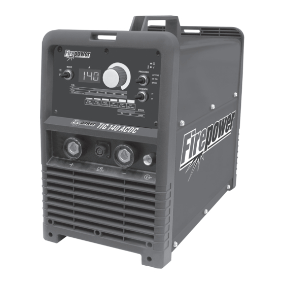
CAUTION 2.04 Description A CAUTION refers to possible equipment The FIREPOWER TIG 140 AC/DC is a single phase damage. constant current welding inverter capable of performing NOTE SMAW (STICK), GTAW (HF TIG) and GTAW (LIFT TIG) welding processes. -
Page 28: User Responsibility
This equipment or any of its parts should not be altered from standard specification without prior written ap- proval of Firepower. The user of this equipment shall have the sole responsibility for any malfunction which results from improper use or unauthorized modifica-... -
Page 29: Duty Cycle
The thermal cut out will operate if the duty cycle is exceeded. ck Duty Cycle Amperage Art # A-12602 Tig Duty Cycle Amperage Art # A-12603 Figure 2-2: FIREPOWER TIG 140 AC/DC Duty Cycle Manual 0-5355 INTRODUCTION... -
Page 30: Specifications
76.6 VDC / 92.8VAC Protection Class IP23S Table 2-1: FIREPOWER TIG 140 AC/DC Specification Note 1: The Effective Input Current should be used for the determination of cable size & supply requirements. Note 2: Generator Requirements at the Maximum Output Duty Cycle. -
Page 31: Optional Accessories
FIREPOWER TIG 140 AC/DC INTRODUCTION 2.10 Optional Accessories 17 Style TIG Torch .............Part No. 1442-0022 Basic Utility Cart ............Part No. 1444-0900 Foot Control ..............Part No. 1442-0025 Tweco Helmet (USA Only) ......Part No. 1441-0087... -
Page 32: Volt-Ampere Curves
INTRODUCTION FIREPOWER TIG 140 AC/DC 2.11 Volt-Ampere Curves Voltage-Amperage Curves shows maximum voltage and amperage output capabilities of welding power source. Curves of other settings fall between curves shown. TIG AC Volt Amp Curve AC Amps Art # A-12604 TIG DC Volt Amp Curve... - Page 33 FIREPOWER TIG 140 AC/DC INTRODUCTION STICK DC Volt Amp Curve DC Amps Art # A-12606 STICK AC Volt Amp Curve AC Amps Art # A-12607 Figure 2-3: FIREPOWER TIG 140 AC/DC Volt-Amp Curves Manual 0-5355 INTRODUCTION...
- Page 34 INTRODUCTION FIREPOWER TIG 140 AC/DC This page left blank intentionally. INTRODUCTION Manual 0-5355...
-
Page 35: Section 3: Installation, Operation And Setup
INSTALLATION/SETUP FIREPOWER TIG 140 AC/DC SECTION 3: INSTALLATION, OPERATION AND SETUP G. The enclosure design of this power source meets the 3.01 Environment requirements of IP23S as outlined in IEC 60529. This provides adequate protection against solid objects These units are designed for use in environments with (greater than 0.5"... -
Page 36: High Frequency Introduction
FIREPOWER TIG 140 AC/DC INSTALLATION/SETUP WARNING ELECTRIC SHOCK can kill; SIGNIFICANT DC VOLTAGE is present after removal of input power. DO NOT TOUCH live electrical parts. SHUT DOWN welding power source, disconnect input power employing lockout/tagging procedures. Lock-out/ tagging procedures consist of padlocking line disconnect switch in open position, removing fuses from fuse box, or shutting OFF and red-tagging circuit breaker or other disconnecting device. -
Page 37: High Frequency Interference
INSTALLATION/SETUP FIREPOWER TIG 140 AC/DC 3.06 High Frequency Interference Interference may be transmitted by a high frequency initiated or stabilized arc welding machine in the following ways. 1. Direct Radiation: Radiation from the machine can occur if the case is metal and is not properly grounded. It can occur through apertures such as open access panels. - Page 38 FIREPOWER TIG 140 AC/DC INSTALLATION/SETUP 7. The time of day that welding or other activities are to be carried out. 8. The immunity of other equipment in the environment: the user shall ensure that other equipment being used in the environment is compatible: this may require additional protection measures.
-
Page 39: 140 Ac/Dc Power Source Controls, Indicators And Features
INSTALLATION/SETUP FIREPOWER TIG 140 AC/DC 3.08 140 AC/DC Power Source Controls, Indicators and Features MODE PROCESS LIFT TIG HF TIG Weld STICK Current TRIGGER (Aluminum) Amps (Mild & Stainless Steel) 22 ga. 18 ga. 16 ga. 1/8" 3/16" 1/4" (0.8 mm) (1.2 mm) - Page 40 During the time of cooling the power source should remain ON such that the fan continues to operate allowing the unit to cool sufficiently. If after 30 minutes with the fan running the Fault Indicator has not gone OFF then have an Accredited Firepower Service Provider check the power source. INSTALLATION, OPERATION AND SETUP...
- Page 41 Switch OFF the power source immediately to allow all components to cool down for at least 30 minutes. If after 30 minutes “Err 000” is displayed and Fault Indicator illuminates when the power source is switched back ON turn the power source OFF and have an Accredited Firepower Service Provider check the power source.
-
Page 42: Firepower Tig 140 Ac/Dc - Stick
The 140 AC/DC is fitted with a cooling fan that will operate continuously when the ON/OFF switch on the rear panel is switched to the ON position. 3.09 FIREPOWER TIG 140 AC/DC - STICK Select Stick mode with the Process Selection switch. -
Page 43: Firepower Tig 140 Ac/Dc - Lift Tig And Hf Tig Mode
INSTALLATION/SETUP FIREPOWER TIG 140 AC/DC 3.10 FIREPOWER TIG 140 AC/DC – LIFT TIG and HF TIG Mode Select Lift TIG or HF TIG with the Process Selection switch. Select either AC or DC output with the Mode switch. Use the Control to adjust the weld current. -
Page 44: Victor Regulator
FIREPOWER TIG 140 AC/DC INSTALLATION/SETUP 3.12 Victor Regulator Pressure regulator (Figure 3-7) attached to the cylinder valve reduce high cylinder pressures to suitable low working pressures for welding, cutting, and other applications. HIGH PRESSURE LOW PRESSURE GAUGE (SUPPLY) GAUGE (DELIVERY) - Page 45 INSTALLATION/SETUP FIREPOWER TIG 140 AC/DC WARNING DO NOT attach or use the regulator if oil, grease, flamma ble substances or damage is present! Have a qualified repair technician clean the regulator or repair any damage. Art # A-12436 Figure 3-8: Regulator to Cylinder Valve 6.
-
Page 46: Specification For Tig Torch
10. Attach the desired downstream equipment. 3.13 Specification for TIG Torch 1. SPECIFICATION FOR TIG TORCH PART NO: W4013600 TO SUIT Firepower 140 AC/DC TIG Torch Contents include: 1 x 17 TIG Torch with Long Back Cap, 12.5 ft lead length, 10.5" gas hose length, 9.5" control lead with 8 pin plug and Rigid Head. -
Page 47: Setup For Tig (Gtaw) Welding
INLET on the rear of the FIREPOWER TIG 140 AC/DC Power Source. Connect the gas hose from the TIG torch to the gas OUTLET on the front of the 140 AC/DC Power Source. - Page 48 FIREPOWER TIG 140 AC/DC INSTALLATION/SETUP MODE PROCESS LIFT TIG HF TIG STICK TRIGGER (Aluminum) Amps (Mild & Stainless Steel) 22 ga. 18 ga. 16 ga. 1/8" 3/16" 1/4" (0.8 mm) (1.2 mm) (1.6 mm) (3.2 mm) (4.7 mm) (6.4 mm)
- Page 49 INSTALLATION/SETUP FIREPOWER TIG 140 AC/DC LIFT TIG (GTAW) Sequence of Operation CAUTION Before any welding is to begin, be sure to wear all appropriate and recommended safety equipment. 1. Switch the ON/OFF Switch (located on the rear panel) to OFF.
-
Page 50: Setup For Stick (Smaw) Welding
FIREPOWER TIG 140 AC/DC INSTALLATION/SETUP 3.15 Setup for STICK (SMAW) Welding A. Connect the Electrode Holder lead to the positive welding terminal (+). If in doubt, consult the electrode manufacturer. Welding current flows from the Power Source via 50mm Dinse type terminals. It is essential, however, that the male plug is inserted and turned securely to achieve a sound electrical connection. - Page 51 INSTALLATION/SETUP FIREPOWER TIG 140 AC/DC PROCESS MODE LIFT TIG HF TIG STICK TRIGGER (Aluminum) Amps (Mild & Stainless Steel) 22 ga. 18 ga. 16 ga. 1/8" 3/16" 1/4" (0.8 mm) (1.2 mm) (1.6 mm) (3.2 mm) (4.7 mm) (6.4 mm)
- Page 52 FIREPOWER TIG 140 AC/DC INSTALLATION/SETUP This page left blank intentionally. INSTALLATION, OPERATION AND SETUP 3-18 Manual 0-5355...
-
Page 53: Section 4: Basic Welding Guide
Electrodes are generally connected to the ELECTRODE HOLDER with the Electrode Holder connected positive polarity. The WORK LEAD is connected negative polarity and is connected to the work piece. If in doubt consult the electrode data sheet or your nearest Accredited Firepower Distributor. Effects of Stick Welding Various Materials A. - Page 54 FIREPOWER TIG 140 AC/DC BASIC WELDING Metal Being Joined Electrode Comments Mild Steel E6011 This electrode is used for all-position welding or for welding on rusty, dirty, less-than-new metal. It has a deep, penetrating arc and is often the first choice for repair or maintenance work.
- Page 55 BASIC WELDING FIREPOWER TIG 140 AC/DC Art # A-07694 Figure 4-8: Overhead Position, Fillet Weld Joint Preparations In many cases, it will be possible to weld steel sections without any special preparation. For heavier sections and for repair work on castings, etc., it will be necessary to cut or grind an angle between the pieces being joined to ensure proper penetration of the weld metal and to produce sound joints.
- Page 56 FIREPOWER TIG 140 AC/DC BASIC WELDING Arc Welding Technique - A Word to Beginners For those who have not yet done any welding, the simplest way to commence is to run beads on a piece of scrap plate. Use mild steel plate about 1/4" (6.0mm) thick and a 1/8" (3.2mm) electrode. Clean any paint, loose scale or grease off the plate and set it firmly on the work bench so that welding can be carried out in the downhand position.
- Page 57 BASIC WELDING FIREPOWER TIG 140 AC/DC Making Welded Joints Having attained some skill in the handling of an electrode, you will be ready to go on to make up welded joints. A. Butt Welds Set up two plates with their edges parallel, as shown in Figure 4-11, allowing 1/16" (1.6mm) to 3/32" (2.4mm) gap between them and tack weld at both ends.
- Page 58 FIREPOWER TIG 140 AC/DC BASIC WELDING C. Vertical Welds B. Fillet Welds 1. Vertical Up These are welds of approximately triangular cross- section made by depositing metal in the corner of Tack weld a three feet length of angle iron to two faces meeting at right angles.
- Page 59 BASIC WELDING FIREPOWER TIG 140 AC/DC Art # A-07703 Figure 4-17: Examples of Vertical Fillet Welds 2. Vertical Down Use a 1/8" (3.2mm) electrode at 100 amps. The tip of the electrode is held in light contact with the work and the speed of downward travel is regulated so that the tip of the electrode just keeps ahead of the slag.
- Page 60 FIREPOWER TIG 140 AC/DC BASIC WELDING The Cause of Distortion Upsetting Weld Art # A-07705_AB Distortion is caused by: Expansion with compression A. Contraction of Weld Metal: Cool Molten steel shrinks approximately 11 per cent Figure 4-19: Parent Metal Expansion in volume on cooling to room temperature.
- Page 61 BASIC WELDING FIREPOWER TIG 140 AC/DC E. Preheating Suitable preheating of parts of the structure other than the area to be welded can be sometimes used to reduce distortion. Figure 4-22 shows a simple application. By removing the heating source from b...
-
Page 62: Stick (Smaw) Welding Troubleshooting
FIREPOWER TIG 140 AC/DC BASIC WELDING 4.02 STICK (SMAW) Welding Troubleshooting FAULT CAUSE REMEDY 1 Welding current ARC FORCE control knob Reduce the ARC FORCE control knob until weld- varying is set at a value that ing current is reasonably constant while prohibit-... - Page 63 BASIC WELDING FIREPOWER TIG 140 AC/DC FAULT CAUSE REMEDY 4 A groove has been A Welding current is too A Reduce welding current. formed in the base high. metal adjacent to B Welding arc is too long. B Reduce the length of the welding arc.
-
Page 64: Tig (Gtaw) Basic Welding Technique
FIREPOWER TIG 140 AC/DC BASIC WELDING FAULT CAUSE REMEDY 7 Crack occurring in A Rigidity of joint. A Redesign to relieve weld joint of severe stresses weld metal soon or use crack resistance electrodes. after solidification B Insufficient throat thick-... - Page 65 BASIC WELDING FIREPOWER TIG 140 AC/DC Guide for Selecting Filler Wire Diameter Filler Wire Diameter DC Current Range (Amps) 1/16" (1.6mm) 20-90 3/32" (2.4mm) 65-115 1/8" (3.2mm) 100-165 3/16" (4.8mm) 200-350 Table 4-4: Filler Wire Selection Guide Tungsten Electrode Types...
- Page 66 TIG Welding is generally regarded as a specialised process that requires operator competency. While many of the principles outlined in the previous Arc Welding section are applicable a comprehensive outline of the TIG Welding process is outside the scope of this Operating Manual. For further information please refer to www.firepower.com or contact Firepower.
-
Page 67: Tig (Gtaw) Welding Problems
BASIC WELDING FIREPOWER TIG 140 AC/DC 4.04 TIG (GTAW) Welding Problems FAULT CAUSE REMEDY 1 Excessive bead build up or Welding current is too Increase weld current and/or faulty joint poor penetration or poor preparation. fusion at edges of weld. - Page 68 FIREPOWER TIG 140 AC/DC BASIC WELDING FAULT CAUSE REMEDY 7 Dirty weld pool A Electrode contaminated A Clean the electrode by grinding off the by contact with work contaminates. piece or filler rod mate- rial. B Work piece surface has B Clean surface.
-
Page 69: Section 5: Power Source Problems And Routine Service Requirements
If major complex subassemblies are faulty, then the Welding Power Source must be returned to an accredited Firepower Service Provider for repair. The basic level of troubleshooting is that which can be performed without special equipment or knowledge. Refer also to section 4 for solving welding problems. -
Page 70: Routine Service And Calibration Requirements
The inspection and testing of the power source and associated accessories shall be carried out in accordance with Section 5 of IEC/ANSI 60974-1: Safety in Welding and Allied Processes-Part 2 Electrical. This includes an insula- tion resistance test and an earthing test to ensure the integrity of the unit is compliant with Firepower original specifications. - Page 71 2. The earth terminal of the associated plug of a transportable power source Note that due to the dangers of stray output currents damaging fixed wiring, the integrity of fixed wiring sup- plying Firepower welding power sources should be inspected by a licensed electrical worker in accordance with the requirements below - 1.
-
Page 72: Cleaning The Welding Power Source
If equipment is to be used in a hazardous location or environments with a high risk of electrocution as outlined in IEC/ANSI 60974-1, then the above tests should be carried out prior to entering this location. B. Calibration Requirements Where applicable, the tests outlined in Table 5-3 below shall be conducted by an accredited Firepower service provider. Testing Requirements... -
Page 73: Section 6: Key Spare Parts
SPARE PARTS FIREPOWER TIG 140 AC/DC SECTION 6: KEY SPARE PARTS 6.01 Power Source Art # A-12612 Figure 6-1 Manual 0-5355 KEY SPARE PARTS... - Page 74 FIREPOWER TIG 140 AC/DC SPARE PARTS FIREPOWER TIG 140 AC/DC Spare Parts Item Part Number Description W7006773 PCB display W7006771 PCB aux power supply W7006775 PCB HF W7006776 PCB primary inverter W7005505 PCB AC output drive W7006772 PCB control W7005507...
-
Page 75: Appendix 1 : Circuit Diagram
APPENDIX FIREPOWER TIG 140 AC/DC APPENDIX 1 : CIRCUIT DIAGRAM Art # A-12613 Manual 0-5355 APPENDIX... -
Page 76: Appendix 2 : Firepower Tig 140 Ac/Dc Setup Guide
FIREPOWER TIG 140 AC/DC APPENDIX APPENDIX 2 : FIREPOWER TIG 140 AC/DC SETUP GUIDE APPENDIX Manual 0-5355... - Page 77 APPENDIX FIREPOWER TIG 140 AC/DC Art# A-12643 Manual 0-5355 APPENDIX...
-
Page 78: Firepower - Limited Warranty Terms
OR CONSEQUENTIAL DAMAGES, SUCH AS, BUT NOT LIMITED TO, LOST PROFITS AND BUSINESS INTERRUPTION. The remedies of the Purchaser set forth herein are exclusive and the liability of Firepower with respect to any contract, or anything done in connection therewith such as the performance or breach thereof, or from the manufacture, sale,... -
Page 79: Warranty Schedule
* 2 years on Power Supply Components 2 Years Parts / No Labor Auto-Darkening Welding Helmet (electronic Lens), ** 1 Month Harness Assy Firepower Regulator for Firepower MST 220i (No labor) 90 days parts / No Labor Remote Controls MIG and TIG Torches (Supplied with power sources) - Page 80 T E C H N O L O G I E S ™ U.S. Customer Care: 800-426-1888 / FAX 800-535-0557 Canada Customer Care: 905-827-4515 / FAX 800-588-1714 International Customer Care: 940-381-1212 / FAX 940-483-8178 Printed in China © 2012 Victor Technologies International, Inc. www.firepower.com...
Need help?
Do you have a question about the TIG 140 AC/DC and is the answer not in the manual?
Questions and answers