
Related Manuals for Firepower TIG 200 AC/DC


Summary of Contents for Firepower TIG 200 AC/DC
- Page 1 Firepower TIG 200 AC/DC Inverter Arc Welder Operating Manual English Canadien Français Americas Español A-12707 Revision: AA Issue Date: November 13, 2014 Manual No.: 0-5370 www.firepoweronline.com...
- Page 2 WE APPRECIATE YOUR BUSINESS! Congratulations on receiving your new Firepower product. We are proud to have you as our customer and will strive to provide you with the best service and support in the industry. This product is backed by our extensive warranty and world-wide service network.
- Page 3 While the information contained in this Manual represents the Manufacturer's best judgement, the Manufacturer assumes no liability for its use. Welding Power Supply Operating Manual Number 0-5370 for: Firepower TIG 200 AC/DC, Machine Only Part Number 1442-0033 Firepower TIG 200 AC/DC, System...
-
Page 4: Table Of Contents
TABLE OF CONTENTS SECTION 1: SAFETY INSTRUCTIONS AND WARNINGS ............1-1 1.01 Arc Welding Hazards ..................1-1 1.02 General Safety Information for firepower CS Flowmeter/Regulator ....1-5 1.03 Principal Safety Standards ................1-7 1.04 Symbol Chart ....................1-8 1.05 Precautions De Securite En Soudage A L’arc ..........1-9 1.06... - Page 5 TABLE OF CONTENTS SECTION 4: BASIC WELDING GUIDE ................4-1 4.01 STICK (SMAW) Basic Welding Technique ............4-1 4.02 STICK (SMAW) Welding Troubleshooting ............. 4-10 4.03 TIG (GTAW) Basic Welding Technique ............4-12 4.04 TIG (GTAW) Welding Problems ..............4-15 SECTION 5: POWER SOURCE PROBLEMS AND ROUTINE SERVICE REQUIREMENTS ............
- Page 6 This Page Intentionally Blank...
-
Page 7: Safety Instructions And Warnings
SAFETY INSTRUCTIONS FIREPOWER TIG 200 AC/DC SECTION 1: SAFETY INSTRUCTIONS AND WARNINGS WARNING PROTECT YOURSELF AND OTHERS FROM POSSIBLE SERIOUS INJURY OR DEATH. KEEP CHILDREN AWAY. PACEMAKER WEARERS KEEP AWAY UNTIL CONSULTING YOUR DOCTOR. DO NOT LOSE THESE INSTRUCTIONS. READ OPERATING/INSTRUCTION MANUAL BEFORE INSTALLING, OPERATING OR SERVICING THIS EQUIPMENT. -
Page 8: Safety Instructions
FIREPOWER TIG 200 AC/DC SAFETY INSTRUCTIONS 3. Use protective screens or barriers to protect others from flash and glare; warn others not to watch the arc. WARNING 4. Wear protective clothing made from durable, flame-resistant material (wool and leather) and foot ARC RAYS can burn eyes and skin;... - Page 9 SAFETY INSTRUCTIONS FIREPOWER TIG 200 AC/DC 1. Keep your head out of the fumes. Do not breathe 7. Do not weld on closed containers such as tanks or the fumes. drums. 2. If inside, ventilate the area and/or use exhaust at the 8.
- Page 10 FIREPOWER TIG 200 AC/DC SAFETY INSTRUCTIONS 8. Read and follow instructions on compressed 4. To prevent accidental starting during servicing, gas cylinders, associated equipment, and CGA disconnect negative (-) battery cable from publication P-1 listed in Safety Standards. battery. 5. Keep hands, hair, loose clothing, and tools away from moving parts.
-
Page 11: General Safety Information For Firepower Cs Flowmeter/Regulator
SAFETY INSTRUCTIONS FIREPOWER TIG 200 AC/DC The following is a quotation from the General Conclu- 1.02 GENERAL SAFETY INFORMATION sions Section of the U.S. Congress, Office of Technology FOR FIREPOWER CS Assessment, Biological Effects of Power Frequency FLOWMETER/REGULATOR Electric & Magnetic Fields - Background Paper, OTA- BP-E-63 (Washington, DC: U.S. - Page 12 FIREPOWER TIG 200 AC/DC SAFETY INSTRUCTIONS C. Ventilation WARNING Ade quately ventilate welding, heating, and cutting work areas to prevent accumula- tion of explosive or toxic concen trations of gases. Certain combinations of metals, Art # A-12127 Figure 1-1: Gas Cylinders coatings, and gases generate toxic fumes.
-
Page 13: Principal Safety Standards
SAFETY INSTRUCTIONS FIREPOWER TIG 200 AC/DC CAUTION Open the cylinder valve slightly. If you open the valve too much, the cylinder could tip over. When crack- ing the cylinder valve, DO NOT stand directly in front of the cylinder valve. Always perform cracking in a well ventilated area. -
Page 14: Symbol Chart
FIREPOWER TIG 200 AC/DC SAFETY INSTRUCTIONS 1.04 Symbol Chart Note that only some of these symbols will appear on your model. Wire Feed Function Single Phase Wire Feed Towards Workpiece With Three Phase Output Voltage Off. Three Phase Static Frequency Converter-... -
Page 15: Precautions De Securite En Soudage A L'arc
SAFETY INSTRUCTIONS FIREPOWER TIG 200 AC/DC 1.05 PRECAUTIONS DE SECURITE EN SOUDAGE A L’ARC MISE EN GARDE LE SOUDAGE A L’ARC EST DANGEREUX PROTEGEZ-VOUS, AINSI QUE LES AUTRES, CONTRE LES BLESSURES GRAVES POSSIBLES OU LA MORT. NE LAISSEZ PAS LES ENFANTS S’APPROCHER, NI LES PORTEURS DE STIMULATEUR CARDI- AQUE (A MOINS QU’ILS N’AIENT CONSULTE UN MEDECIN). - Page 16 FIREPOWER TIG 200 AC/DC SAFETY INSTRUCTIONS 11. Ne touchez pas à l’électrode lorsqu’en contact avec le circuit de soudage (terre). 12. N’utilisez que des équipements en bon état. Réparez AVERTISSEMENT ou remplacez aussitôt les pièces endommagées. LE RAYONNEMENT DE L’ARC PEUT BRÛLER 13.
- Page 17 SAFETY INSTRUCTIONS FIREPOWER TIG 200 AC/DC 2. Portez des lunettes de sécurité approuvées. Des écrans latéraux sont recommandés. 3. Entourez l’aire de soudage de rideaux ou de cloisons AVERTISSEMENT pour protéger les autres des coups d’arc ou de LE SOUDAGE PEUT CAUSER UN INCENDIE l’éblouissement;...
- Page 18 FIREPOWER TIG 200 AC/DC SAFETY INSTRUCTIONS 8. Lisez et respectez les consignes relatives aux bouteilles de gaz comprimé et aux équipements connexes, ainsi que la publication P-1 de la CGA, AVERTISSEMENT identifiée dans la liste de documents ci-dessous. LES ETINCELLES ET LES PROJECTIONS BRULANTES PEUVENT CAUSER DES BLESSURES.
-
Page 19: Informations Générales De Sécurité
SAFETY INSTRUCTIONS FIREPOWER TIG 200 AC/DC 1. Assurez-vous que les portes, les panneaux, les 1. N’ôtez pas le bouchon de radiateur tant que le moteur capots et les protecteurs soient bien fermés. n’est pas refroidi. 2. Avant d’installer ou de connecter un système, arrêtez 2. - Page 20 FIREPOWER TIG 200 AC/DC SAFETY INSTRUCTIONS B. Entretien des Locaux AVERTISSEMENT AVERTISSEMENT Mettez en pratique les procédures de sécurité et de mode opératoire suivantes à Ne laissez jamais l’oxygène en contact avec chaque fois que vous utilisez cet appareil la graisse, l’huile ou d’autres substances de régulation de pression.
-
Page 21: Principales Normes De Securite
SAFETY INSTRUCTIONS FIREPOWER TIG 200 AC/DC AVIS 1.08 Principales Normes De Securite Ce document CGA p. t peut être obtenu en Safety in Welding and Cutting, norme ANSI Z49.1, écrivant à “Compressed Gas Association”, American Welding Society, 550 N.W. LeJeune Rd., 4221 Walney Roed, 5th Floor. -
Page 22: Graphique De Symbole
FIREPOWER TIG 200 AC/DC SAFETY INSTRUCTIONS 1.09 Graphique de Symbole Seulement certains de ces symboles apparaîtront sur votre modèle. Déroulement du Fil Sous Tension Mono Phasé Alimentation du Fil Vers la Pièce de Fabrication Hors Tension Trois Phasé Hors Tension... -
Page 23: Declaration Of Conformity
SAFETY INSTRUCTIONS FIREPOWER TIG 200 AC/DC 1.05 Declaration of Conformity Declaration of Conformity Victor Technologies International Inc. 16052 Swingley Ridge Road Suite 300 Chesterfield, MO 63033 U.S.A. in accordance with the following Directive(s) • 2006/95/EC The Low Voltage Directive • 2004/108/EC The Electromagnetic Compatibility (EMC) Directive... - Page 24 FIREPOWER TIG 200 AC/DC SAFETY INSTRUCTIONS Classification: The equipment described in this manual is Class A and intended for industrial use. WARNING This Class A equipment is not intended for use in residential locations where the electrical power is provided by the public low-voltage supply system. There may be potential difficul- ties in ensuring electromagnetic compatibility in those locations, due to conducted as well as radiated disturbances.
-
Page 25: Introduction
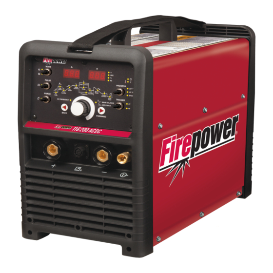
CAUTION 2.04 DESCRIPTION A CAUTION refers to possible equipment The Firepower 200 AC/DC is a single phase constant damage. current welding inverter capable of performing SMAW NOTE (STICK), GTAW (HF TIG) and GTAW (LIFT TIG) welding processes. -
Page 26: User Responsibility
This equipment or any of its parts should not be altered • Shoulder Strap from standard specification without prior written ap- • Operating Manual & CD proval of Firepower. The user of this equipment shall have the sole responsibility for any malfunction which • Firepower Cap results from improper use or unauthorized modifica-... -
Page 27: Specifications
INTRODUCTION FIREPOWER TIG 200 AC/DC 186 AC/DC SMAW (STICK) GTAW (TIG) SAFE OPERATING REGION (TIG & STICK) 100 110 120 130 140 150 160 170 180 190 200 210 220 Welding Current (AMPS) A-11493 Figure 2-2: 200 AC/DC Duty Cycle 2.09 SPECIFICATIONS... -
Page 28: Optional Accessories
FIREPOWER TIG 200 AC/DC INTRODUCTION Note 1: The Effective Input Current should be used for the determination of cable size & supply requirements. Note 2: Generator Requirements at the Maximum Output Duty Cycle. 2.10 OPTIONAL ACCESSORIES 26 Style TIG Torch with Remote Current Control ..Part No. -
Page 29: Installation, Operation And Setup
INSTALLATION FIREPOWER TIG 200 AC/DC SECTION 3: INSTALLATION, OPERATION AND SETUP G. The enclosure design of this power source meets the 3.01 ENVIRONMENT requirements of IP23S as outlined in EN 60529. This These units are designed for use in environments with... -
Page 30: High Frequency Introduction
FIREPOWER TIG 200 AC/DC INSTALLATION WARNING ELECTRIC SHOCK can kill; SIGNIFICANT DC VOLTAGE is present after removal of input power. DO NOT TOUCH live electrical parts. SHUT DOWN welding power source, disconnect input power employing lockout/tagging procedures. Lock-out/ tagging procedures consist of padlocking line disconnect switch in open position, removing fuses from fuse box, or shutting OFF and red-tagging circuit breaker or other disconnecting device. -
Page 31: High Frequency Interference
INSTALLATION FIREPOWER TIG 200 AC/DC 3.06 HIGH FREQUENCY INTERFERENCE Interference may be transmitted by a high frequency initiated or stabilized arc welding machine in the following ways. 1. Direct Radiation: Radiation from the machine can occur if the case is metal and is not properly grounded. It can occur through apertures such as open access panels. - Page 32 FIREPOWER TIG 200 AC/DC INSTALLATION 6. Equipment used for calibration and measurement. 7. The time of day that welding or other activities are to be carried out. 8. The immunity of other equipment in the environment: the user shall ensure that other equipment being used in the environment is compatible: this may require additional protection measures.
-
Page 33: 200 Ac/Dc Power Source Controls, Indicators And Features
INSTALLATION FIREPOWER TIG 200 AC/DC 3.08 200 AC/DC Power Source Controls, Indicators and Features Figure 3-1: Controls on Front Panel A-11232 Figure 3-2: Rear Panel Installation Manual 0-5370... - Page 34 FIREPOWER TIG 200 AC/DC INSTALLATION 1. Positive Welding Terminal Positive Welding Terminal (50mm) dinse. Welding current flows from the Power Source via heavy duty bayonet type terminals. It is essential, however, that the male plug is inserted fully and turned clockwise until tight to achieve a sound electrical connection.
- Page 35 Switch OFF the power source immediately to allow all components to cool down for at least 30 minutes. If after 30 minutes “Err 001” is displayed and Fault Indicator illuminates when the power source is switched back ON turn the power source OFF and have an Accredited Firepower Service Provider check the power source.
- Page 36 FIREPOWER TIG 200 AC/DC INSTALLATION 4T Latch Mode This mode of welding is mainly used for long welding runs to reduce operator fatigue. In this mode the operator can press and release the torch trigger and the output will remain active. To deactivate the power source, the trigger switch must again be depressed and realized, thus eliminating the need for the operator to hold the torch trigger.
- Page 37 INSTALLATION FIREPOWER TIG 200 AC/DC 15. Pulse Switch Press the PULSE switch to toggle Pulse On and OFF in LIFT TIG and HF TIG modes 16. Programming Parameter Indicators (Front Panel Display Indicators) The Front Panel LED indicators serve two purposes. First, they show what process and what parameter is selected and the value of that parameter.
-
Page 38: 200 Ac/Dc - Stick Programming Mode
FIREPOWER TIG 200 AC/DC INSTALLATION 19. Digital Voltmeter / Parameter meter The digital volt meter is used to display the actual output voltage of the power source. It is also used to display Parameters in Programming Mode. Depending on the Programming Parameter selected, the status indictor adjacent to the volt meter will illuminate to show the units of the programming parameter. -
Page 39: 200 Ac/Dc - Lift Tig And Hf Tig Programming Mode
INSTALLATION FIREPOWER TIG 200 AC/DC Programming Parameter Adjustment Device Display Hot Start This parameter operates in all weld modes except LIFT TIG mode and is used to heat up the weld zone in TIG modes or improve the Amps start characteristics for stick electrodes the peak start current on top of the WELD current. - Page 40 FIREPOWER TIG 200 AC/DC INSTALLATION A-12717 Adjust programming parameter using Press to go forward / go back between the Multi Function Control knob programming status LED’s Figure 3-6: LIFT TIG and HF TIG Programming Mode Programming Parameter Adjustment Device Display...
- Page 41 INSTALLATION FIREPOWER TIG 200 AC/DC Programming Parameter Adjustment Device Display Weld Current This parameter sets the TIG WELD current when PULSE is OFF. This parameter also sets the Amps STICK weld current. 5 to 200A (DC TIG mode) 30 to 200A (AC LIFT TIG mode)
- Page 42 FIREPOWER TIG 200 AC/DC INSTALLATION Programming Parameter Adjustment Device Display Crater Current This parameter operates in (4T) TIG modes only and is used to set the finish current for TIG. Amps The CRATER Current remains ON until the torch trigger switch...
-
Page 43: Short Circuit Protection While Welding
INSTALLATION FIREPOWER TIG 200 AC/DC Wave Balance = 50% Wave Balance = 10% Wave Balance = 65% Balanced with 50% penetration Maximum Penetration and Maximum Cleaning and and 50% cleaning reduced cleaning reduced penetration A-11223 Table 3-5: AC TIG Wave Balance 3.11 SHORT CIRCUIT PROTECTION WHILE WELDING... - Page 44 FIREPOWER TIG 200 AC/DC INSTALLATION NOTE Flowmeter/Regulators purchased with open 1/8", 1/4", 3/8", or 1/2" NPT ports must be assembled to their intended system. 1. Note the maximum inlet pressure stamped on the Flowmeter/Regulator. DO NOT attach the Flowmeter/ Regulator to a system that has a higher pressure than the maximum rated pressure stamped on the Flowmeter/Regulator.
-
Page 45: Specification For Tig Torch
10. Attach the desired downstream equipment. 3.13 SPECIFICATION FOR TIG TORCH 1. SPECIFICATION FOR TIG TORCH PART NO: W4013600 TO SUIT Firepower 200AC/DC TIG Torch Contents include: 1 x 26 TIG Torch with Long Back Cap, 12.5 ft lead length, 10.5" gas hose length, 9.5" control lead with 8 pin plug and Rigid Head. - Page 46 FIREPOWER TIG 200 AC/DC INSTALLATION A-12703 NOTE: The additional switches/controls below are interchangeable with the installed control in the TIG torch. ART# A-11587 Control module with Control module with Control module with push button on/o push button on/o switch roller potentiometer and switch only.
-
Page 47: Setup For Tig (Gtaw) Welding
INSTALLATION FIREPOWER TIG 200 AC/DC 3.14 SETUP FOR TIG (GTAW) WELDING A. Select Lift TIG or HF TIG mode with the process selection control (refer to Section 3.08.7 for further information). B. Connect the TIG Torch to the negative welding terminal (-). Welding current flows from the power source via heavy duty bayonet type terminals. - Page 48 FIREPOWER TIG 200 AC/DC INSTALLATION Positive Welding Negative Welding Terminal (+) Terminal (-) A-12720 Work Lead 8 Pin Control Socket Tig Torch Figure 3-10: Setup for TIG Welding NOTE When the 200 AC/DC is used with a Remote Foot Control in, depress foot control to maximum to allow max current to be previewed/adjusted on the front panel.
- Page 49 4. Using a secured Argon cylinder, slowly crack open then close the cylinder valve while standing off to the side of the valve. This will remove any debris that may be around the valve & Flowmeter/Regulator seat area. 5. Install the Flowmeter/Regulator (for details of Firepower Flowmeter/Regulator, please refer to 3.18) and tighten with a wrench.
-
Page 50: Setup For Stick (Smaw) Welding
FIREPOWER TIG 200 AC/DC INSTALLATION 3.15 SETUP FOR STICK (SMAW) WELDING A. Connect the Electrode Holder lead to the positive welding terminal (+). If in doubt, consult the electrode manufacturer. Welding current flows from the Power Source via heavy duty bayonet type terminals. It is essential, however, that the male plug is inserted fully and turned clockwise until tight to achieve a sound electrical connection. -
Page 51: Basic Welding Guide
Electrodes are generally connected to the ELECTRODE HOLDER with the Electrode Holder connected positive polarity. The WORK LEAD is connected negative polarity and is connected to the work piece. If in doubt consult the electrode data sheet or your nearest Accredited Firepower Distributor. Effects of Stick Welding Various Materials A. - Page 52 FIREPOWER TIG 200 AC/DC BASIC WELDING GUIDE Metal Being Joined Electrode Comments Mild Steel E6011 This electrode is used for all-position welding or for welding on rusty, dirty, less-than-new metal. It has a deep, penetrating arc and is often the first choice for repair or maintenance work.
- Page 53 BASIC WELDING GUIDE FIREPOWER TIG 200 AC/DC Art # A-07694 Figure 4-8: Overhead Position, Fillet Weld Joint Preparations In many cases, it will be possible to weld steel sections without any special preparation. For heavier sections and for repair work on castings, etc., it will be necessary to cut or grind an angle between the pieces being joined to ensure proper penetration of the weld metal and to produce sound joints.
- Page 54 FIREPOWER TIG 200 AC/DC BASIC WELDING GUIDE Arc Welding Technique - A Word to Beginners For those who have not yet done any welding, the simplest way to commence is to run beads on a piece of scrap plate. Use mild steel plate about 1/4" (6.0mm) thick and a 1/8" (3.2mm) electrode. Clean any paint, loose scale or grease off the plate and set it firmly on the work bench so that welding can be carried out in the downhand position.
- Page 55 BASIC WELDING GUIDE FIREPOWER TIG 200 AC/DC Making Welded Joints Having attained some skill in the handling of an electrode, you will be ready to go on to make up welded joints. A. Butt Welds Set up two plates with their edges parallel, as shown in Figure 4-11, allowing 1/16" (1.6mm) to 3/32" (2.4mm) gap between them and tack weld at both ends.
- Page 56 FIREPOWER TIG 200 AC/DC BASIC WELDING GUIDE B. Fillet Welds C. Vertical Welds 1. Vertical Up These are welds of approximately triangular cross- section made by depositing metal in the corner of Tack weld a three feet length of angle iron to two faces meeting at right angles.
- Page 57 BASIC WELDING GUIDE FIREPOWER TIG 200 AC/DC Art # A-07703 Figure 4-17: Examples of Vertical Fillet Welds 2. Vertical Down Use a 1/8" (3.2mm) electrode at 100 amps. The tip of the electrode is held in light contact with the work and the speed of downward travel is regulated so that the tip of the electrode just keeps ahead of the slag.
- Page 58 FIREPOWER TIG 200 AC/DC BASIC WELDING GUIDE The Cause of Distortion Upsetting Weld Art # A-07705_AB Distortion is caused by: Expansion with compression A. Contraction of Weld Metal: Cool Molten steel shrinks approximately 11 per cent Figure 4-19: Parent Metal Expansion in volume on cooling to room temperature.
- Page 59 BASIC WELDING GUIDE FIREPOWER TIG 200 AC/DC E. Preheating Suitable preheating of parts of the structure other than the area to be welded can be sometimes used to reduce distortion. Figure 4-22 shows a simple application. By removing the heating source from b Art # A-07710_AB Block Sequence.
-
Page 60: Stick (Smaw) Welding Troubleshooting
FIREPOWER TIG 200 AC/DC BASIC WELDING GUIDE 4.02 STICK (SMAW) WELDING TROUBLESHOOTING FAULT CAUSE REMEDY 1 Welding current ARC FORCE control knob Reduce the ARC FORCE control knob until weld- varying is set at a value that ing current is reasonably constant while prohibit-... - Page 61 BASIC WELDING GUIDE FIREPOWER TIG 200 AC/DC FAULT CAUSE REMEDY 4 A groove has been A Welding current is too A Reduce welding current. formed in the base high. metal adjacent to B Welding arc is too long. B Reduce the length of the welding arc.
-
Page 62: Tig (Gtaw) Basic Welding Technique
FIREPOWER TIG 200 AC/DC BASIC WELDING GUIDE FAULT CAUSE REMEDY 7 Crack occurring in A Rigidity of joint. A Redesign to relieve weld joint of severe stresses weld metal soon or use crack resistance electrodes. after solidification B Insufficient throat thick-... - Page 63 BASIC WELDING GUIDE FIREPOWER TIG 200 AC/DC Guide for Selecting Filler Wire Diameter Filler Wire Diameter DC Current Range (Amps) 1/16" (1.6mm) 20-90 3/32" (2.4mm) 65-115 1/8" (3.2mm) 100-165 3/16" (4.8mm) 200-350 Table 4-4: Filler Wire Selection Guide Tungsten Electrode Types...
- Page 64 FIREPOWER TIG 200 AC/DC BASIC WELDING GUIDE Base Metal DC Current DC Current Tungsten Filler Rod Argon Gas Flow Joint Type Thickness for Mild for Stainless Electrode Diameter (if Rate Steel Steel Diameter required) 0.040" 35-45 20-30 0.040" 1/16" 10 CFH(5 LPM) Butt/Corner 1.0mm...
-
Page 65: Tig (Gtaw) Welding Problems
BASIC WELDING GUIDE FIREPOWER TIG 200 AC/DC 4.04 TIG (GTAW) WELDING PROBLEMS FAULT CAUSE REMEDY 1 Excessive bead build up or Welding current is too Increase weld current and/or faulty joint poor penetration or poor preparation. fusion at edges of weld. - Page 66 FIREPOWER TIG 200 AC/DC BASIC WELDING GUIDE FAULT CAUSE REMEDY 7 Dirty weld pool A. Electrode contaminated A. Clean the electrode by grinding off the by contact with work contaminates. piece or filler rod mate- rial. B. Work piece surface has B.
-
Page 67: Section 5: Power Source Problems
If major complex subassemblies are faulty, then the Welding Power Source must be returned to an accredited Firepower Service Provider for repair. The basic level of troubleshooting is that which can be performed without special equipment or knowledge. Refer also to section 4 for solving welding problems. -
Page 68: Routine Service And Calibration Requirements
Section 5 of EN 60974.1: Safety in Welding and Allied Processes-Part 2 Electrical. This includes an insulation resis- tance test and an earthing test to ensure the integrity of the unit is compliant with Firepower original specifications. If equipment is to be used in a hazardous location or environments with a high risk of electrocution as outlined in EN 60974.1, then the above tests should be carried out prior to entering this location. - Page 69 2. The earth terminal of the associated plug of a transportable power source Note that due to the dangers of stray output currents damaging fixed wiring, the integrity of fixed wiring sup- plying Firepower welding power sources should be inspected by a licensed electrical worker in accordance with the requirements below - 1.
-
Page 70: Cleaning The Welding Power Source
If equipment is to be used in a hazardous location or environments with a high risk of electrocution as outlined in EN 60974.1, then the above tests should be carried out prior to entering this location. B. Calibration Requirements Where applicable, the tests outlined in Table 5-3 below shall be conducted by an accredited Firepower service provider. Testing Requirements... -
Page 71: Key Spare Parts
SPARE PARTS FIREPOWER TIG 200 AC/DC SECTION 6: KEY SPARE PARTS 6.01 POWER SOURCE A-11500_AC Figure 6-1 Spare Parts Manual 0-5370... -
Page 72: Spare Parts
FIREPOWER TIG 200 AC/DC SPARE PARTS 200 AC/DC Spare Parts Item Part Number Description W7005500 PCB display W7005503 PCB aux power supply W7005502 PCB HF W7005504 PCB 200ACDC W7005505 PCB AC output drive W7005506 PCB control W7005507 PCB secondary rectifier... -
Page 73: Appendix 1 : Circuit Diagram
APPENDIX FIREPOWER TIG 200 AC/DC APPENDIX 1 : CIRCUIT DIAGRAM A-12719 Appendix Manual 0-5370... -
Page 74: Appendix 2 : 200 Ac/Dc Setup Guide
FIREPOWER TIG 200 AC/DC APPENDIX APPENDIX 2 : 200 AC/DC SETUP GUIDE Appendix Manual 0-5370... - Page 75 APPENDIX FIREPOWER TIG 200 AC/DC A-12718 Appendix Manual 0-5370...
- Page 76 FIREPOWER TIG 200 AC/DC APPENDIX This Page Blank Intentionally Appendix Manual 0-5370...
- Page 77 This Page Intentionally Blank...
- Page 78 OR CONSEQUENTIAL DAMAGES, SUCH AS, BUT NOT LIMITED TO, LOST PROFITS AND BUSINESS INTERRUPTION. The remedies of the Purchaser set forth herein are exclusive and the liability of Firepower with respect to any contract, or anything done in connection therewith such as the performance or breach thereof, or from the manufacture, sale,...
-
Page 79: Warranty Schedule
* 2 years on Power Supply Components 2 Years Parts / No Labor Auto-Darkening Welding Helmet (electronic Lens), ** 1 Month Harness Assy Firepower Flowmeter/Regulator for Firepower MST 220i (No labor) 90 days parts / No Labor Remote Controls MIG and TIG Torches (Supplied with power sources) - Page 80 THE AMERICAS Denton, TX USA U.S. Customer Care Ph 1-800-426-1888 (tollfree) Fax: 1-800-535-0557 (tollfree) International Customer Care Ph 1-940-381-1212 Fax: 1-940-483-8178 Miami, FL USA Sales Office, Latin America Ph 1-954-727-8371 Fax: 1-954-727-8376 Oakville, Ontario, Canada Canada Customer Care Ph 1-905-827-4515 Fax: 1-800-588-1714 (tollfree) EUROPE Chorley, United Kingdom...
Need help?
Do you have a question about the TIG 200 AC/DC and is the answer not in the manual?
Questions and answers