Table of Contents
Advertisement
Revision A: 1502250001, Content updated.
Models:
MSMBB-12CRDN1-MP0W
MSMBC-18CRDN1-MP0W
MSMBD-22CRDN1-MP5W
Table of Contents
1.
Precaution
2.
3.
4.
5.
6.
7.
8.
9.
•
Installation MUST conform with local building codes or, in the absence of local codes, with the
National Electrical Code NFPA70/ANSI C1-1993 or current edition and Canadian Electrical
Code Part1 CSA C.22.1.
•
The information contained in the manual is intended for use by a qualified service technician
familiar with safety procedures and equipped with the proper tools and test instruments
•
Installation or repairs made by unqualified persons can result in hazards to you and others.
•
Failure to carefully read and follow all instructions in this manual can result in equipment
malfunction, property damage, personal injury and/or death.
This Manual I s F or Qualified S ervice E ngineer U se Only
SERVICE MANUAl
Mini Split 3D
DC Inverter Air Conditione r
Advertisement
Table of Contents

Related Manuals for Midea MSMBB-12CRDN1-MP0W


Summary of Contents for Midea MSMBB-12CRDN1-MP0W
- Page 1 SERVICE MANUAl Mini Split 3D Revision A: 1502250001, Content updated. DC Inverter Air Conditione r Models: MSMBB-12CRDN1-MP0W MSMBC-18CRDN1-MP0W MSMBD-22CRDN1-MP5W Table of Contents Precaution Part Names Dimension Refrigerant Cycle Diagram Printed Circuit Board Connector Wiring Diagram of Outdoor Unit Installation Details...
-
Page 2: Table Of Contents
Table Of Contents 1. Precaution ..............................1 1.1 Safety Precaution .......................... 1 1.2 Warning ............................1 2. Part Names ..............................4 2.1 Model Names of Indoor/Outdoor units ..................4 2.2 Part names of Indoor/Outdoor units ....................5 3. Dimension ..............................6 3.1 Indoor Unit ............................. -
Page 3: Precaution
Sharp edges could cause injury, be especially careful of the case edges and the fins on the 1. Precaution condenser and evaporator. For installation, always contact the 1.1 Safety Precaution dealer or an authorized service center. To prevent injury to the user or other Do not install the product on a people and property damage, the following defective installation stand. - Page 4 There is risk of electric shock or fire. product. It can avoid vibration of water leakage. Stop operation and close the window in storm or hurricane. If possible, remove Do not install the product where the the product from the window before the noise or hot air from the outdoor unit could hurricane arrives.
- Page 5 Use a firm stool or ladder when cleaning or maintaining the product. Be careful and avoid personal injury. Replace the all batteries in the remote control with new ones of the same type. Do not mix old and new batteries or different types of batteries.
-
Page 6: Part Names
2. Part Names 2.1 Model Names of Indoor/Outdoor units Outdoor units Series Capacity Indoor units MSMBB-12CRDN1-MP0W MOB1-12CDN1-MP0W Inverter MSMBC-18CRDN1-MP0W MOC-18CDN1-MP0W MSMBD-22CRDN1-MP5W MOF1-22CDN1-MP5W... -
Page 7: Part Names Of Indoor/Outdoor Units
2.2 Part names of Indoor/Outdoor units... -
Page 8: Dimension
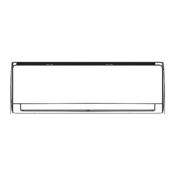
3. Dimension 3.1 Indoor Unit Model 810 mm 200 mm 300 mm MSMBB-12CRDN1-MP0W (31.89in) (7.87in) (11.81in) 980 mm 225 mm 325 mm MSMBC-18CRDN1-MP0W (38.58in) (8.86in) (12.80in) 1090 mm 235 mm 338 mm MSMBD-22CRDN1-MP5W (42.91in) (9.25in) (13.31in) - Page 9 For MSMBB-12CRDN1-MP0W, For MSMBC-18CRDN1-MP0W, For MSMBD-22CRDN1-MP5W,...
-
Page 10: Outdoor Unit
3.2 Outdoor Unit More than 30cm(11.8in) More than 60cm(23.6in) (Service space) More than 30cm(11.8in) More than 60cm(23.6in) More than 70cm(27.6in) Note: The above drawing is only for reference. The appearance of your units may be different. Model 780mm 250mm 540mm 843mm 549mm 276mm... -
Page 11: Refrigerant Cycle Diagram
4. Refrigerant Cycle Diagram For cooling only models, INDOOR OUTDOOR LIQUID SIDE CAPILIARY TUBE HEAT HEAT EXCHANGE EXCHANGE (EVAPORATOR) (CONDENSER) GAS SIDE COMPRESSOR... -
Page 12: Printed Circuit Board Connector Wiring Diagram Of Outdoor Unit
5. Printed Circuit Board Connector Wiring Diagram of Outdoor unit MOB1-12CDN1-MP0W, CAPACITOR Voltage 290-330VDC (standby) connect TO REACTOR 210-300VDC (Running) CN27 CN26 2-10V AC(standby); AC FAN-CAPACITOR 30-150V AC(running); 208-230VAC CN20 CN19 connect to outdoor AC FAN [1.4]2014.02.20 3-4 0VAC / 208-230VAC (high speed running) CN19 AC_FAN 2-4 0VAC / 208-230VAC (low speed Running) - Page 13 MOF1-22CDN1-MP5W...
-
Page 14: Installation Details
Please refer to the nameplate before selecting the cable, fuse and switch. 6.3 Pipe length and the elevation Pipe size Models Liquid 3/8in 1/4in MSMBB-12CRDN1-MP0W+MOB1-12CDN1-M P0W (Ф9.52mm) (Ф6.35mm) 1/2in 1/4in MSMBC-18CRDN1-MP0W+MOC-18CDN1-M P0W (Ф12.7mm) (Ф6.35mm) MSMBD-22CRDN1-MP5W+MOF1-22CDN1-... -
Page 15: Installation For The First Time
manifold (usually yellow) to the vacuum pump. 6.4 Installation for the first time ully open the handle for the low pressure 4) F Air and moisture in the refrigerant system have gauge. undesirable effects as below: Start the vacuum pump and operate according ●... -
Page 16: Adding The Refrigerant After Running The System For Many Years
to the 3 way valve service port must be in the open position. and a charging 3rd step; the air in the gauge hoses needs to be cylinder to the service port of the 3-way valve. Open the valve on the refrigerant container and purged out. - Page 17 pressure will rise during this time, this is normal. There will be some pressure left in the system this is normal, The indoor unit is now ready to be serviced. Disconnect the charge set, and tighten the 2-way and 3-way valve’s stem nuts. Use a torque wrench to tighten the 3-way valves = 13.27 service port cap to a torque of 18N.m(...
- Page 18 any air moisture and noncodensables from the Procedure: refrigeration circuit. After 50 seconds has passed 1). Confirm that both the 2-way and 3-way tighten the hose on the low pressure gauge. The valves are set to the opened position. sweep is now complete. 2).
- Page 19 charged with a little at a time (approximately 150g each time) , operating the air conditioner in the cooling cycle; however, one time is not sufficient, wait approximately 1 minute and then repeat the procedure. 5).When the electronic scale displays the proper weight, disconnect the charge hose from the 3-way valve’s service port immediately If the system has been charged with liquid...
-
Page 20: Operation Characteristics
7. Operation Characteristics Temperature Cooling operation Heating operation Drying operation Mode 17℃~32℃ 0℃~30℃ 10℃~32℃ Room temperature (62℉~90℉) (32℉~86℉) (50℉~90℉) °C ~50 °C °F ~122 °F °C ~50 °C °C ~30 °C °C ~50 °C Outdoor temperature °F °F °F °F °F ~122 °F... -
Page 21: Electronic Function
8. Electronic function Dispalys ‘ ’ for three seconds when Fresh, Swing, Turbo or Silence feature is cancelled. 8.1 Abbreviation Dispalys ‘ ’ under deforsting operation. T1: Indoor room temperature Dispalys ‘ ’ when anti-cold air feature is T2: Coil temperature of evaporator activated under heating mode. -
Page 22: Main Protection
8.3 Main Protection function. 8.3.7 Compressor preheating functions 8.3.1 Three minutes delay at restart for Preheating permitting condition: compressor When T4(outdoor ambient temperature)< Less than 1 minute delay for the 1 time 3°C(37.4°F), the preheating function will be stand-up and 3 minutes delay for others. activated. -
Page 23: Operation Modes And Functions
8.4 Operation Modes and Functions 8.4.2.2 Indoor fan running rules In cooling mode, indoor fan runs all the time 8.4.1 Fan mode and the speed can be selected as high, (1) Outdoor fan and compressor stop. medium, low and auto. (2) Temperature setting function is disabled, When the setting temp. - Page 24 8.4.4 Auto-mode This mode can be chosen with remote 8.4.6 Forced operation function controller and the setting temperature can be 8.4.6.1 Enter forced operation function: changed between 17°C(62.6°F)~30°C(86°F). When the machine is off, pressing the touch In auto mode, the machine will choose cooling, button will carry the machine to forced auto heating or fan-only mode according to ΔT mode.
- Page 26 7.4.10 Point check function Press the LED DISPLAY or LED or MUTE button of the remote controller three times, and then press the AIR DIRECTION or SWING button three times in ten seconds, the buzzer will keep ring for two seconds.
- Page 27 Enquiry Display value Meaning Remark information T1,T2,T3,T4, -1F,-1E,-1d,-1c,- -25,-24,-23,-22,-21,-2 1. All the displaying temperature is actual T2B,TP,TH, 1b,-1A value. 2. All the temperature is °C no matter what Targeted -19—99 -19—99 Frequency, kind of remote controller is used. A0,A1,…A9 100,101,…109 Actual 3.
-
Page 28: Troubleshooting
9. Troubleshooting Safety Electricity power is still kept in capacitors even the power supply is shut off. Do not forget to discharge the electricity power in capacitor. Electrolytic Capacitors (HIGH VOLTAGE! CAUTION!) For other models, please connect discharge resistance (approx.100Ω 40W) or soldering iron (plug) between +, - terminals of the electrolytic capacitor on the contrary side of the outdoor PCB. -
Page 29: Indoor Unit Error Display
9.1 Indoor Unit Error Display Operation Timer lamp Display LED STATUS lamp ☆ 1 time Indoor unit EEPROM parameter error ☆ 2 times Indoor / outdoor units communication error ☆ 3 times Zero-crossing signal detection error ☆ 4 times Indoor fan speed has been out of control Indoor room temperature sensor T1 open circuit or short ☆... -
Page 30: Outdoor Unit Error Display
9.2 Outdoor unit error display MOB1-12CDN1-MP0W, [1.4]2014.02.20 CN19 AC_FAN PFC-1310 CN27 CN20 FAN_C CN60 SSR1 4-WAY-N 4-WAY-L CN21 CN26 FAN_C CN12 CN11 IC10 PTC1 C148 CN14 TestPort Earth E2-Burning CN28 CN25 IPM1 DSA1 C113 LED2 C100 CN22 T3-Tipe T4-OutDoor IC4-1 R145 HIN2 LED1... - Page 31 MOC-18CDN1-MP0W LED2 LED1 Problems IU display (Green) (Red) standby for normal Operation normally ☆ IPM malfunction or IGBT over-strong current protection Over voltage or too low voltage protection ☆ Over voltage or too low voltage protection ☆ Inverter compressor drive error ☆...
- Page 32 MOF1-22CDN1-MP5W...
-
Page 33: Diagnosis And Solution
9.3 Diagnosis and Solution 9.3.1 EEPROM parameter error diagnosis and solution(E0/F4) E0/F4 Error Code Malfunction decision Indoor or outdoor PCB main chip does not receive feedback conditions from EEPROM chip. Supposed causes Installation mistake ● PCB faulty ● Trouble shooting: Power off , then restart the unit 2 minutes later. - Page 34 9.3.2 Indoor / outdoor unit’s communication diagnosis and solution(E1) Error Code Malfunction decision Indoor unit does not receive the feedback from outdoor unit during conditions seconds and this condition happens four times continuously. Supposed causes Wiring mistake ● Indoor or outdoor PCB faulty ●...
- Page 35 Remark: Use a multimeter to test the DC voltage between L2 port and S port of outdoor unit. The red pin of multimeter connects with L2 port while the black pin is for S port. When AC is normal running, the voltage will move alternately between -50V to 50V.
- Page 36 9.2.3 Zero crossing detection error diagnosis and solution(E2)...
- Page 37 9.3.4 Fan speed has been out of control diagnosis and solution(E3) E3/F5 Error Code Malfunction decision When indoor fan speed keeps too low (300RPM) for certain time, conditions the unit will stop and the LED will display the failure. Supposed causes Wiring mistake ●...
- Page 38 Index 1: 1:Indoor or Outdoor DC Fan Motor(control chip is in fan motor) Power on and when the unit is in standby, measure the voltage of pin1-pin3, pin4-pin3 in fan motor connector. If the value of the voltage is not in the range showing in below table, the PCB must has problems and need to be replaced.
- Page 39 supply)or 50V(115V power supply), the PCB must has problems and need to be replaced.
- Page 40 9.3.5 Open circuit or short circuit of temperature sensor diagnosis and solution(E5) E4/E5/F1/F2/F3 Error Code Malfunction decision If the sampling voltage is lower than 0.06V or higher than 4.94V, conditions the LED will display the failure. Supposed causes Wiring mistake ●...
- Page 41 9.3.6 Refrigerant Leakage Detection diagnosis and solution(EC) Error Code Malfunction decision Define the evaporator coil temp.T2 of the compressor just starts conditions running as Tcool. In the beginning 5 minutes after the compressor starts up, if T2 °C( °F) <Tcool-2 Tcool-35.6 does not keep continuous 4 seconds and this situation happens 3 times, the display area will...
- Page 42 9.3.7 Overload current protection diagnosis and solution(F0) Error Code Malfunction decision An abnormal current rise is detected by checking the specified conditions current detection circuit. Supposed causes Power supply problems. ● System blockage ● PCB faulty ● Wiring mistake ● Compressor malfunction ●...
- Page 43 9.3.8 IPM malfunction or IGBT over-strong current protection diagnosis and solution(P0) Error Code Malfunction decision When the voltage signal that IPM send to compressor drive chip is abnormal, the display LED will show “P0” and AC will turn off. conditions Supposed causes Wiring mistake ●...
- Page 44 For example: Note: The photos below are only for reference, it’s may be not same totally with the ones on your side.
- Page 47 9.3.9 Over voltage or too low voltage protection diagnosis and solution(P1) Error Code Malfunction decision An abnormal voltage rise or drop is detected by checking the conditions specified voltage detection circuit. Supposed causes Power supply problems. ● System leakage or block ●...
- Page 48 9.3.10 High temperature protection of compressor top diagnosis and solution(P2) Error Code Malfunction decision If the sampling voltage is not 5V, the LED will display the failure. conditions Supposed causes Power supply problems. ● System leakage or block ● PCB faulty ●...
- Page 49 9.3.11 Inverter compressor drive error diagnosis and solution(P4) Error Code Malfunction decision An abnormal inverter compressor drive is detected by a special conditions detection circuit, including communication signal detection, voltage detection, compressor rotation speed signal detection and so on. Supposed causes Wiring mistake ●...
- Page 50 Main parts check 1. Temperature sensor checking Disconnect the temperature sensor from PCB, measure the resistance value with a tester. Temperature sensors. Room temp.(T1) sensor, Indoor coil temp.(T2) sensor, Outdoor coil temp.(T3) sensor, Outdoor ambient temp.(T4) sensor, Compressor discharge temp.(T5) sensor. Measure the resistance value of each winding by using the multi-meter.
- Page 51 Appendix 1 Temperature Sensor Resistance Value Table for T1,T2,T3,T4 (°C--K) °C °F °C °F °C °F °C °F K Ohm K Ohm K Ohm K Ohm 115.266 12.6431 2.35774 0.62973 108.146 12.0561 2.27249 0.61148 101.517 11.5 2.19073 0.59386 96.3423 10.9731 2.11241 0.57683 89.5865...
- Page 52 Appendix 2 Temperature Sensor Resistance Value Table for T5 (°C --K) °C °F °C °F °C °F °C °F K Ohm K Ohm K Ohm K Ohm 542.7 68.66 13.59 3.702 511.9 65.62 13.11 3.595 62.73 12.65 3.492 455.9 59.98 12.21 3.392 430.5...
- Page 53 Appendix 3: °C °F °C °F °C °F °C °F °C °F 69.8 123.8 179.6 235.4 24.8 71.6 125.6 181.4 237.2 26.6 73.4 127.4 183.2 28.4 75.2 129.2 240.8 30.2 186.8 242.6 25.5 77.9 132.8 188.6 244.4 32.9 78.8 134.6 190.4 246.2 33.8...
- Page 54 2.Compressor checking Measure the resistance value of each winding by using the tester. Position Resistance Value ASN98D22UEZ ASM135D23UFZ DA150S1C-20FZ(F) Blue - Red 1.57Ω 1.75Ω 0.95Ω Blue - Black (20℃/68℉) (20℃/68℉) (20℃/68℉) Red - Blue...
- Page 55 3. IPM continuity check Turn off the power, let the large capacity electrolytic capacitors discharge completely, and dismount the IPM. Use a digital tester to measure the resistance between P and UVWN; UVW and N. Digital tester Normal resistance value Digital tester Normal resistance value (+)Red...
- Page 56 5: Pressure On Service Port Cooling chart: °F °C (23.89) (29.44) (35) (40.56) (46.11) 70/59 10.1 75/63 10.7 80/67 11.2 °F °C (23.89) (29.44) (35) (40.56) (46.11) 70/59 75/63 80/67 °F °C (23.89) (29.44) (35) (40.56) (46.11) 70/59 0.82 0.78 0.81 0.86 1.01...
- Page 57 Heating Chart: °F 57/53 47/43 37/33 27/23 17/13 °C (13.89/11.67) (8.33/6.11) (2.78/0.56) (-2.78/-5) (-8.33/-10.56) 30.3 28.5 25.3 22.8 20.8 32.5 30.0 26.6 25.4 23.3 33.8 31.5 27.8 26.3 24.9 °F 57/53 47/43 37/33 27/23 17/13 °C (13.89/11.67) (8.33/6.11) (2.78/0.56) (-2.78/-5) (-8.33/-10.56) °F 57/53...
-
Page 58: Disassembly Instructions
10 Disassembly Instructions Note: This part is for reference, the photos may have slight difference with your machine. 10.1 Indoor unit Parts name Procedures Remarks Front panel How to remove the front panel. Pull the below side of the panel toward you and remove the cover Release the connector of the display ass’y. - Page 59 Electrical How to remove the electrical parts parts. ② Remove the front panel from procedure 1. Pull out the room temp. sensor (T1). Remove the two screws for the ground ③ connection. Remove the fixing screw. ② Pull out the coil temp. sensor.
- Page 60 Evaporator How to remove the evaporator. After remove the electrical parts from procedure 2, disassemble the pipe holder ① at the rear side of the unit. Remove the screws on the ② evaporator at the fixed plate. ③ Remove the two screws on the evaporator at the base bearing side.
- Page 61 Fan motor How to remove the fan motor. and Fan Remove the front panel, electrical parts and evaporator following procedure 1-3. Remove the two screws and remove the fixing board of fan motor. ② Remove the fixing screw . ③ Pull out the fan motor and fan ass’y from the side direction.
- Page 62 10.2 Outdoor unit Ø MOB1-12CDN1-MP0W Part name Procedures Remarks Panel plate How to remove the panel plate. Top cover 1) Stop operation of the air conditioner and turn “OFF” the power breaker. Remove the top cover.(8 screws) Remove the front panel.(10 screws) Remove the side Front panel...
- Page 63 Electrical How to remove the electrical parts parts. Perform work of item ② 1,2. Remove the wires connected with the compressor. (On the IPM ) Remove the wires ③ Two blue connected with 4-way valve. wires Remove the red wire connected with the capacitor Remove the blue wire ④...
- Page 64 compressor. Perform work of item ② 1,2,3. Remove ground wire and remove the discharge pipe and suction pipe with a burner. Remove the nuts and washers fixing the compressor on bottom plate. Lift the compressor ③ from the base pan assembly.
- Page 65 Ø MOC-18CDN1-MP0W Part name Procedures Remarks Panel plate How to remove the panel plate. Stop operation of the air conditioner and turn “OFF” the power breaker. Remove the top cover.(6 screws) Remove the front panel.(10 screws) Remove the side panel.(10 screws) Fan ass’y How to remove the fan ass’y.
- Page 66 parts. Perform work of item ② 1,2. Remove the two connectors for the compressor and the reactors. Remove two blue wires connected with the four way ③ valve. Remove the connectors for the condenser coil temp. sensor(T3),outdoor ambient ④ T3,T4,T5 temp.
- Page 67 Perform work of item 1,2,3. Remove the ground wire ② and remove the discharge pipe and suction pipe with a burner. 3) Remove the hex nuts and washers fixing the compressor on bottom plate. 4) Lift the compressor ③ from the base pan assembly.
- Page 68 Ø MOF1-22CDN1-MP5W Remarks Parts name Procedures Panel plate How to remove the panel plate. Top cover Stop operation of the air conditioner and turn “OFF” the power breaker. Side panel Remove the top cover.(9 screws) Remove the front panel.(2 screws) Air outlet panel Remove the side Front panel...
- Page 69 Remove the fan ⑤3 screws motor. Electrical How to remove the electrical parts parts. Perform work of item ② 1,2. Remove the screw on the middle metal plate. Remove the wires connected with the compressor.(Red wire connects with terminal one, the blue wire and white wire connect with the compressor ③3 pcs wires.
- Page 70 Compressor How to remove the compressor. Perform work of item ③ 1,2,3. Remove the ground wire and remove the discharge pipe and suction pipe with a burner. Remove the nuts and washers fixing the compressor ④ on bottom plate. Lift the compressor from the base pan assembly.
Need help?
Do you have a question about the MSMBB-12CRDN1-MP0W and is the answer not in the manual?
Questions and answers