Advertisement
Quick Links
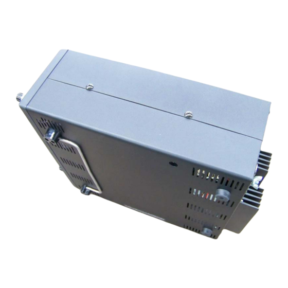
INSTRUCTION MANUAL – MODEL AT588K
Model AT588K is a user-installable kit to add the internal automatic antenna tuner to an
existing model 588 Omni-VII transceiver. Instructions, complete with color photos of
relevant detail, are included in this manual.
Model AT588K is a "no-solder" kit. You will need the following tools:
#10 Torx wrench (provided with the kit, Ten-Tec part #38313).
Small pair of needle nose pliers.
2 Philips screwdrivers, one small, one large.
We recommend you read this manual in its entirety before beginning installation of the
tuner kit.
Should you have difficulty installing the tuner or need advice, our service department is
available to provide technical support from 8 a.m. to 5 p.m. USA Eastern time by calling
(865) 428-0364.
Ten-Tec, Inc., 1185 Dolly Parton Parkway, Sevierville, TN 37862 USA
Sales: (800) 833-7373. General Info and Office: (865) 453-7172.
Service: (865) 428-0364. Visit us on the web at
www.tentec.com
Ten-Tec part #74431
Version 1 – February 2009
Advertisement

Subscribe to Our Youtube Channel
Related Manuals for Ten-Tec AT588K


Summary of Contents for Ten-Tec AT588K
- Page 1 INSTRUCTION MANUAL – MODEL AT588K Model AT588K is a user-installable kit to add the internal automatic antenna tuner to an existing model 588 Omni-VII transceiver. Instructions, complete with color photos of relevant detail, are included in this manual. Model AT588K is a “no-solder” kit. You will need the following tools: #10 Torx wrench (provided with the kit, Ten-Tec part #38313).
- Page 2 There are 2 large black Philips screws on each side of the case. Remove these 4 screws. Around the rear perimeter of the top and bottom covers are #10 Torx screws. Use the provided Torx wrench to remove them. Ten-Tec part #74431 Version 1 – February 2009...
- Page 3 9B just under the external speaker jack as pointed out in the above photo. Pull the socket off the connector and pull the wire out from the black grommets. Set top cover with speaker intact aside. Ten-Tec part #74431 Version 1 – February 2009...
- Page 4 4 small black Philips screws holding the plate in place. Remove the first two shown in each corner here, then turn the radio upside down and remove the remaining two. Turn the radio right side up after the bottom two are removed. Ten-Tec part #74431 Version 1 – February 2009...
- Page 5 4. This is the view of the rear low pass filter board after the tuner shield has been removed. Ten-Tec part #74431 Version 1 – February 2009...
- Page 6 5. Remove the autotuner board from the packing kit and place it onto the tuner shield as shown above. 4 screws, Ten-Tec part #60069 are provided in the packing kit to attach the tuner board to the shield. There is only one possible correct orientation of the board to the shield due to the way the standoffs are set on the board.
- Page 7 (shown here with three additional black cables routed through the same grommet). This cable will be plugged into the autotuner board in a later step. Ten-Tec part #74431 Version 1 – February 2009...
- Page 8 #32 cable end into the socket. Picture shown here is with the #32 cable successfully in place of #31. Ten-Tec part #74431 Version 1 – February 2009...
- Page 9 8. Turn the radio upside down. Along the left side of the radio is a multi-wire cable bundle with an unplugged connector marked 19 on one end that is partially tucked inside a plastic grommet. Ten-Tec part #74431 Version 1 – February 2009...
- Page 10 8. Unfurl the cable to its full length, then thread the connector end through the two plastic grommets as shown above. Leave this cable unplugged. It will be plugged into the autotuner board in a later step. Ten-Tec part #74431 Version 1 – February 2009...
- Page 11 OUTPUT. Plug cable #31 into the connector marked INPUT as shown in the illustration. Please note with the board correct side up for installation that the printing on the PC board is oriented in the other direction and will be shown upside down (see photo). Ten-Tec part #74431 Version 1 – February 2009...
- Page 12 11. Insert tuner board and shield into the radio as shown. Attach the two black screws removed in step 3 into the two corners of the shield. Ten-Tec part #74431 Version 1 – February 2009...
- Page 13 3. The #19 cable that was routed to the back of the radio in step 9 is now ready to be plugged into connector J1. (Pen used as pointer). Ten-Tec part #74431 Version 1 – February 2009...
- Page 14 13. There is a small piece of paper inserted between the battery clip and the battery used in the autotuner. Remove this piece of paper. The autotuner installation is now complete. Ten-Tec part #74431 Version 1 – February 2009...
- Page 15 ON, and enter the transceiver menu. There is a line item marked AUTOTUNER which must be turned to ON to actuate the tuner. Tuner operation instructions are provided in the Omni-VII owners manual. Ten-Tec part #74431 Version 1 – February 2009...
- Page 16 Ten-Tec part #74431 Version 1 – February 2009...
Need help?
Do you have a question about the AT588K and is the answer not in the manual?
Questions and answers