Advertisement
Quick Links
Ten-Tec Argonaut V (Model 516) Low Output Repair
(Note: Those undertaking this repair do so at their own risk. The
procedures outlined located a faulty band-switch diode and worked for me.
Your circumstances may differ (i.e. the problem may be another component).
This procedure has not been approved by Ten-Tec, Inc. or any of its staff.)
Symptoms:
My Argonaut V developed a problem with low output power on all bands except 80
metres. The output on 80 was 20 watts on 160 it was 12 and on 40 metres 10 watts. On
the upper frequencies power dropped off to approximately 1 to 2 watts.
Troubleshooting:
Section 4.5.1 and 4.5.2 of the manual describe the transmit band switching circuit. The
circuits are in schematic diagrams Argonaut V Pwr Amp (pages 2, 3 and 4 of 5).
The switching circuit applies approximately +8 volts to the appropriate band circuitry and
connects the power amplifier with the rest of the transmitter section. All other bands
should have approximately –150 volts (with the Argonaut V at full power).
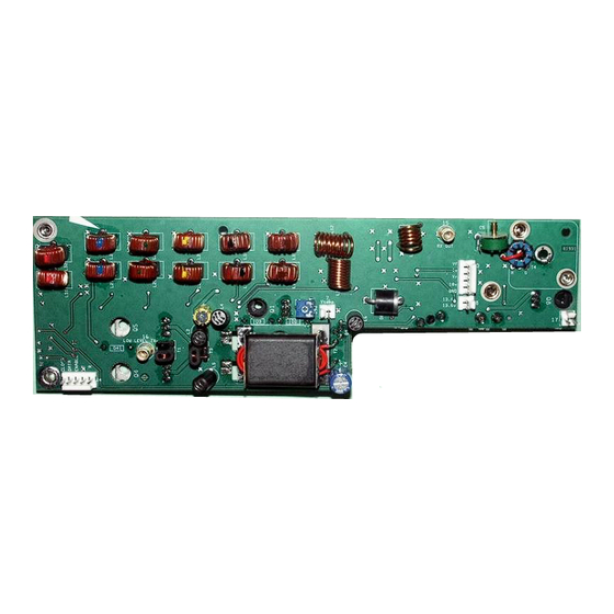
With the top off of the rig you can access all the necessary test locations to determine if
the band switch circuitry is functioning properly (use caution). A series of coils are
located on the circuit board (see figure 1) that is attached to the heat sink. These coils are
a part of the various band-switching stages and are connected to the Bandout rail. They
are identified as 160 metres (L32) at the left, L28, L24, L21, L18, L15 and end with the
15 through 10 metre coil (L12) at the right. (The latter coil is air wound all others are
wound on ferrite cores.)
Figure 1: Test points (PA board removed from rig)
Test voltages can be checked with the PA board in the rig and the top cover removed.
The voltages (referenced to chassis ground) are measured where the coil is attached to the
Original document located at:
https://www.ve7tk.ca/
Advertisement

Related Manuals for Ten-Tec Argonaut V


Summary of Contents for Ten-Tec Argonaut V
- Page 1 Section 4.5.1 and 4.5.2 of the manual describe the transmit band switching circuit. The circuits are in schematic diagrams Argonaut V Pwr Amp (pages 2, 3 and 4 of 5). The switching circuit applies approximately +8 volts to the appropriate band circuitry and connects the power amplifier with the rest of the transmitter section.
- Page 2 4. Unplug all inter-connecting cables attached to the boards on the rear heat sink 5. Remove the 4 screws that attach the back panel to the Argonaut V. 6. Remove the screws holding the antenna connector (2), power plug (1) plus the counter-sunk screw in the upper right of the heat sink.
- Page 3 Using solder-wick unsolder and lift all six leads. Carefully straighten the leads to allow them to pass through the slot when the board is lifted. Figure 2: Enlargement of Transformer T2 with red wire primary (Note: Slots and solder pads to left end of T2) 12.
- Page 4 20. Test the Argonaut into a dummy load and reinstall it back into service. Acknowledgements: Special thanks to the following for their troubleshooting assistance and encouragement: Ten-Tec service manager Paul Clinton and his staff Members of the Ten-Tec Reflector (www.contesting.com/_tentec) Members of the Ten-Tec516 Yahoo Group ...
Need help?
Do you have a question about the Argonaut V and is the answer not in the manual?
Questions and answers