Advertisement
Quick Links
Ten-Tec (865) 453-7172
Service Department (865) 428-4483
Upgrading the Jupiter PLD (Programmable Logic Device)
to add support for a plug-in keyboard
BACKGROUND
The logic board in the Ten-Tec Jupiter transceiver contains a PLD (Programmable Logic Device) that
provides the DSP system with enhanced I/O (Input-Output) capability. In order to support the new CW
keyboard interface this PLD must be upgraded. The Logic board was designed to allow the DSP processor
to perform this upgrade using special firmware from Ten-Tec.
SPECIAL NOTE
If you have a Jupiter with a factory installed blue LCD display then you do not need to perform the PLD
update. If you are updating your Jupiter to the new Multi-Program memory chip you should perform the
PLD update while the old chip is in the radio. Then, after updating the PLD you can remove the old
memory chip and install the new one.
HOW TO PERFORM THE PLD UPDATE
The new PLD firmware file is similar to other radio firmware upgrades. However, this firmware will only
need to be run once. After downloading the PLD update package from
www.rfsquared.com
you will need
to perform a standard update using the file 538KBD.RUF. Once the PC utility completes downloading the
firmware, the radio will begin executing the firmware start the process of updating the on-board PLD. This
process will take up to 3 minutes. During the time the PLD is being reprogrammed the
RED TX LED
will
turn on. During this phase of the update operation it is critical that the radio not be tuned off. Doing so may
leave the PLD in a state that will prevent it from operating normally and may require the radio to be
returned to Ten-Tec for service. When the PLD programming is completed the
RED TX LED
will go out
and the
GREEN RX LED
will turn on. You will also hear the relays in the radio click as they are reset. At
this point the power to the radio should be cycled. You should see the message "PLD IS PROGRAMMED.
NOW UPDATE FIRMWARE" displayed on the screen.
At this point, you should reprogram the radio firmware or install the new IC, depending on the level of
upgrade you are performing.
Advertisement

Related Manuals for Ten-Tec Jupiter 538 Series


Summary of Contents for Ten-Tec Jupiter 538 Series
- Page 1 BACKGROUND The logic board in the Ten-Tec Jupiter transceiver contains a PLD (Programmable Logic Device) that provides the DSP system with enhanced I/O (Input-Output) capability. In order to support the new CW keyboard interface this PLD must be upgraded. The Logic board was designed to allow the DSP processor to perform this upgrade using special firmware from Ten-Tec.
-
Page 2: Tools Needed
TOOLS NEEDED: Phillips Screwdriver 3/16” Nut Driver Pliers Soldering Iron (Resistor Change) T10 Torx Tool (Ten-Tec p/n 38313)* 0.050 Allen Wrench (Ten-Tec p/n 38040)* 0.062 Allen Wrench (Ten-Tec p/n 38088)* *Included Ten-Tec p/n 74421... - Page 3 Step 1: Remove the four large Phillips head screws on the sides of the Jupiter.
- Page 4 Step 2: Remove the torx head screws on the rear of the Jupiter using the T-10 torx tool provided. These 10 torx screws help to secure both the top and bottom covers.
- Page 5 Step 3: Remove the top cover from the chassis by lifting from the back and pulling the lip out from the front panel.
- Page 6 Step 4: The speaker is located on the top cover. Use care removing the top cover to avoid doing any damage to the speaker wire. Unplug the speaker wire at connector #17 as shown. Feed the wire through the hole in the chassis and set the top cover and mounting hardware aside for now.
- Page 7 Step 5: Remove the bottom cover from the chassis by lifting from the back and pulling the lip out from the front panel. Set the bottom cover aside for now.
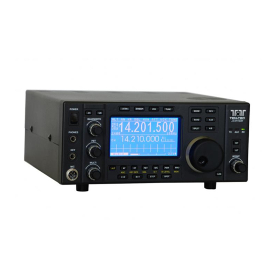
- Page 8 This image is a picture of the front panel with the LCD that will be removed. The unit pictured is a Model 538CE with a tuner. Not all versions of the 538 will look exactly like the one pictured.
- Page 9 Step 6: Remove the four small Phillips head screws securing the front panel to the sides of the chassis. Keep the screws in a safe place as they will be needed for reassembly.
- Page 10 Step 7: Some versions of the Jupiter will have a few capacitors soldered from the mic jack to a ground lug attached to the chassis. In order to release the front panel on these versions of the Jupiter, remove the nut and screw that secure the ground lug to the chassis.
- Page 11 Step 8: Gently pull the front panel straight out from the chassis about an inch. Begin unplugging the cables that run to the front panel (note that each cable has a number corresponding to a printed number on the board with the exception of cable #12).
- Page 12 Step 9: Once the front panel has been completely released from the chassis, find a surface that will not scratch the panel and lay the panel face down.
- Page 13 Step 10: Using a 3/16 hex driver, find and remove the four nuts that secure the LCD to the front panel (Note that at least one of the nuts may have a small nylon washer between it and the board. This nylon washer is used as an insulator and will NOT be used as an insulator on the new display).
- Page 14 Step 11: Gently lift the LCD from the front panel.
- Page 15 At this point, this is how the back side of the front panel should look.
- Page 16 A Choice to Make? Please choose one of the two options. The first option is to change the four threaded studs for studs that are slightly longer. This first option prevents the LCD Panel from being stressed in case of over tightening.
- Page 17 The second option is to do nothing and leave the threaded studs as they are and proceed with the installation of the new display. The second option is recommended for those who are uncomfortable taking the front panel completely apart. However, should the second option be chosen, be aware that the LCD panel ABSOLUTELY must not be over tightened.
- Page 18 Option 1: Changing the short threaded studs for the longer threaded studs. Step 12: To begin removing the main tuning knob, first remove the knob sleeve by sliding the knob sleeve forward.
- Page 19 Step 13: Using the 0.062 Allen Wrench, loosen the set screw and pull forward on the main tuning knob until it releases from the encoder shaft. DO NOT remove the set screw. Only loosen the set screw until the knob will slide off of the encoder shaft.
- Page 20 Step 14: Remove the Bandwidth, PBT, Multi, and RIT/XIT knobs. First, slide the knob sleeves forward exposing the opening to the set screw. The sleeves can be quite tight making them very difficult to remove. For assistance, use the flat blade of a screwdriver and pry the knob sleeve off.
- Page 21 Step 15: Using the 0.050 Allen Wrench, loosen the set screws and pull forward on the knobs until they release from the encoder shafts. DO NOT remove these set screws.
- Page 22 Step 16: For radios with rubber O-Rings on the encoder shafts (Bandwidth, PBT, MULTI, and RIT/XIT), slide the O-Rings from the encoder shafts and put them aside along with the knobs until reassembly of the front panel.
- Page 23 Step 17: Unscrew all of the screws that secure the front panel PCB to the front panel. There are 21 screws in all. Once removed, the front panel PCB will release from the molded plastic front panel. The screw just below the mic jack secures a grounding tab.
- Page 24 Step 18: Using a pair of needle nose pliers, grip the standoff at the base as shown. Rotate counter- clockwise to loosen the standoff from the stud. If the standoff will not loosen from the stud on this attempt, then the base of the stud (on the other side of the board) itself may need to be gripped with another pair of pliers.
- Page 25 Step 19: Take the longer threaded studs that came in the kit and insert them through the same four holes in the exact same direction as the four that were just removed. Next, take the four nylon washers that were previously removed and insert them on the threaded studs.
- Page 26 These will look exactly as before except that the threaded studs are longer.
- Page 27 Step 20: Reassemble the front panel taking the front panel PCB and insert it back into the molded plastic front panel. Align all of the front panel buttons and drop in place.
- Page 28 Step 21: Attach the front panel PCB to the molded plastic front panel with the 21 screws that were removed earlier.
- Page 29 Do not forget the grounding tab at the mic connector.
- Page 30 Step 22: For radios with O-Rings, slide the O-Rings back on to the encoder shafts for the Bandwidth, PCB, Multi, and RIT/XIT encoders.
- Page 31 Step 23: Place the knobs back on to the encoder shafts in the same manner in which they were disassembled and tighten the set screws. Be careful not to over tighten.
- Page 32 Step 24: Slide the knob sleeves back on to the knobs.
- Page 33 Step 25: Repeat for the main encoder.
- Page 34 Step 26: Slide the knob sleeve over the main encoder.
- Page 35 Step 27: Remove the new blue LCD from the packaging.
- Page 36 Step 28: Take the new blue LCD and set it into place on the four standoffs that were just installed. The display will only properly fit into the front panel one way.
- Page 37 Step 29: Take the four nuts that were set aside when the old panel was removed and use them to secure the new panel. Be careful not to over tighten the nuts. Proceed to Step 34.
- Page 38 Option 2 Step 30: Remove the new blue LCD from the packaging.
- Page 39 Step 31: Locate the four standoffs for the LCD and place two nylon washers on the two standoffs that are nearest the three encoders (leave the other two standoffs as they are). These standoffs have threaded studs coming out from the center.
- Page 40 Step 32: Place the new LCD on the threaded studs on the front panel as shown.
- Page 41 Step 33: Place the four nuts back on the threaded studs and tighten. Do not over tighten. If needed, push on the panel only slightly in each corner to get the nut(s) started. Watch closely and do not over stress the panel.
- Page 42 Step 34: Slide the front panel back on to the side panels of the chassis. Position the four plastic tabs on the front panel to the outside of the chassis side panels. Plug the cables back into the corresponding connectors. Remember that cable #12 does not have a number on the board.
- Page 43 Step 35: Note that with the new LCD and Model 538 versions with the chassis shield (the piece with the flexible brass grounding tabs); the two-pin connector slightly brushes against the shield when the front panel is replaced. Simply maneuver the connector to get it by the chassis shield.
- Page 44 Step 36: The flat ribbon cables should be plugged in just as they were before they were unplugged. The smaller one (#2) can be somewhat difficult to insert into its socket if it is not aligned just right. Be careful not to bend the corners trying to get it plugged in (bent corners will make it next to impossible to get it plugged in and may damage the cable).
- Page 45 Step 37: On versions of the Model 538 that have the capacitors from the mic jack to the chassis, now is the time to reattach the lug to the chassis using the hardware that had been previously set aside.
- Page 46 Step 38: Now that all of the cables have been reconnected, reattach the front panel to the chassis using the hardware that had been previously set aside (two of these screws may have already been inserted if the pivot option was chosen earlier). At this point, double check all cables to ensure proper seating into their corresponding connectors.
- Page 47 Open the Firmware Upgrade Instructions (p/n 74422) and follow Steps 4 – 7, then return here to Step 39. Step 39: Inspect the Logic Board (shown above). There are two 100 Ohm resistors (marked 101) that must be changed to 0 Ohm resistors. They are R147 and R148.
- Page 48 Step 40: This step requires use of a soldering iron. Some soldering experience is recommended here. Using some tweezers, place the 0 Ohm resistors on top of the existing 100 Ohm (marked 101) resistors that are already there. Proceed by soldering the 0 Ohm resistors at R147 and R148.
- Page 49 Step 41: If the Model 538 had a tuner, now is the time to reinstall the tuner deck. Position the tuner deck in the chassis as shown and line up the four screw holes. No tuner, proceed to Step 43.
- Page 50 Step 42: Using the hardware that was set aside earlier, reattach the tuner chassis. Notice also in the picture above, the routing of the tuner wires. Be careful not to pinch any of these wires when reinstalling the tuner deck.
- Page 51 Step 43: Before putting the top cover back on, connect the speaker as shown. Feed the cable back through the hole in the chassis and plug it into connector #17. DO NOT PLUG into the spare connector next to it. Please ensure that the cable is plugged into connector #17.
- Page 52 Step 44: Install the top and bottom covers. Work the bottom cover into the lip in the front panel and push forward aligning the holes. Do the same for the top cover also working the cover together at the lip along the side panel.
- Page 53 Step 45: Screw the ten Torx head screws back into the rear of the Jupiter.
- Page 54 Step 46: Screw the four large Phillips head screws back into the sides of the Jupiter. Congratulations! Turn the power on and enjoy! Every effort has been made to ensure that the information contained in this document is accurate, and that the modification may easily be performed in the field. However, caution should be taken as unwarranted damage to the radio may result.
Need help?
Do you have a question about the Jupiter 538 Series and is the answer not in the manual?
Questions and answers