Viessmann VITOCELL-V 100 Installation Instructions Manual
Dhw cylinder
Hide thumbs
Also See for VITOCELL-V 100:
- Installation instructions manual (24 pages) ,
- Service instruction (24 pages) ,
- Operation manual (4 pages)

Subscribe to Our Youtube Channel
Related Manuals for Viessmann VITOCELL-V 100


Summary of Contents for Viessmann VITOCELL-V 100
-
Page 1: Installation Instructions
VIESMANN Installation instructions for contractors Vitocell-V 100 Type CVA DHW cylinder Vitocell-W 100 Type CVA DHW cylinder VITOCELL-V 100 VITOCELL-W 100 Dispose after installation. 5862 890 GB 5/2006... -
Page 2: Safety Instructions
Safety instructions Please follow these safety instructions closely to prevent accidents and material losses. Safety instructions explained & the Code of Practice of relevant trade associations, Please note & all current safety regulations as This symbol warns against the defined by DIN, EN, DVGW, TRGI, risk of material losses and TRF, VDE and all locally applicable environmental pollution. -
Page 3: Table Of Contents
Index Installation information Product information ..................& Connections .................... & Installation notes ..................Installation sequence Installing the DHW cylinder (up to 300 litres capacity) ......... & Fitting the cylinder temperature sensor and the thermometer sensor (if supplied) ....................& Checking the anode connection and inserting the facia......Installing the DHW cylinder (500 litres) ............ -
Page 4: Product Information
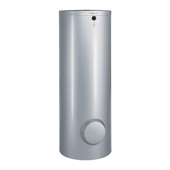
Product information Vitocell-V 100 and Vitocell-W 100 Enamel-coated DHW cylinder with Contents: internal indirect coils for DHW heating 160, 200, 300, 500, 750 and 1000 in conjunction with freestanding and litres wall mounted boilers and/or EHO electric immersion heater (300 and Suitable for systems conforming to 500 litres capacity). -
Page 5: Connections
Product information (cont.) Connections 160 to 500 litres capacity 750 and 1000 litres capacity Drain Drain HR Heating water return HR Heating water return Heating water flow Heating water flow KW Cold water KW Cold water STS Cylinder temperature sensor STS Cylinder temperature sensor Magnesium anode with earth Magnesium anode with earth... -
Page 6: Installation Notes
Product information (cont.) Installation notes Please note & Allow an adequate distance to the To prevent material losses, wall to enable the thermostat (if install the DHW cylinder in a installed) to be operated. room free from the risk of frost &... -
Page 7: Installing The Dhw Cylinder (Up To 300 Litres Capacity)
Installing the DHW cylinder (up to 300 litres capacity) Please note The thermal insulation must not be able to come into contact with naked flames. Exercise caution when welding and soldering. Fitting the cylinder temperature sensor and the thermometer sensor (if supplied) &... -
Page 8: Checking The Anode Connection And Inserting The Facia
Installing the DHW cylinder (up to 300 litres . . . (cont.) & Never wrap insulating tape around the sensor. & Insert the sensor retainer together with the sensor into the sensor well until it bottoms out. Checking the anode connection and inserting the facia A Magnesium anode B Earth lead... -
Page 9: Installing The Dhw Cylinder (500 Litres)
Installing the DHW cylinder (up to 300 litres . . . (cont.) Note Guide the thermometer lead through the nut in the flange insulation mat. Installing the DHW cylinder (500 litres) Please note The thermal insulation must not be able to come into contact with naked flames. - Page 10 Installing the DHW cylinder (500 litres) (cont.)
- Page 11 Installing the DHW cylinder (500 litres) (cont.)
- Page 12 Installing the DHW cylinder (500 litres) (cont.)
- Page 13 Installing the DHW cylinder (500 litres) (cont.) Note After 30 minutes the thermal insulation casing has adapted to the contours of the cylinder. Then hook closure strip into the final notch.
-
Page 14: Fitting The Type Plate And Thermometer (If Supplied)
Installing the DHW cylinder (500 litres) (cont.) Fitting the type plate and thermometer (if supplied) 1. Fit the thermometer (if supplied). 3. Close all apertures. 2. Fit the thermometer sensor. 4. Affix the type plate. -
Page 15: Checking The Anode Connection And Fitting The Lid
Installing the DHW cylinder (500 litres) (cont.) Checking the anode connection and fitting the lid A Magnesium anode B Earth lead... -
Page 16: Fitting The Cylinder Temperature Sensor
Installing the DHW cylinder (500 litres) (cont.) Fitting the cylinder temperature sensor Note & Secure the sensor on the outside of the location spring of the sensor retainer (not in the groove) so that it is flush with the front of the spring. &... -
Page 17: Installing The Dhw Cylinder (From 750 Litres)
Installing the DHW cylinder (from 750 litres) Please note The thermal insulation must not be able to come into contact with naked flames. Exercise caution when welding and soldering. Installing the DHW cylinder... -
Page 18: Testing The Anode Connection
Installing the DHW cylinder (from 750 litres) (cont.) Testing the anode connection A Magnesium anode B Earth lead Note Check that the earth cable is connected to the magnesium anode. -
Page 19: Fitting The Thermal Insulation
Installing the DHW cylinder (from 750 litres) (cont.) Fitting the thermal insulation... - Page 20 Installing the DHW cylinder (from 750 litres) (cont.) Note After 30 minutes the thermal insulation casing has adapted to the contours of the cylinder. Then hook closure strip into the final notch.
- Page 21 Installing the DHW cylinder (from 750 litres) (cont.) 1. Fit the thermal insulation casing by 3. Insert the thermometer sensor lead patting it tightly against the cylinder through the inlet, push the thermo- body. meter in and fit the cover strips to the front.
-
Page 22: Fitting The Lid
Installing the DHW cylinder (from 750 litres) (cont.) Fitting the lid A Viessmann logo... -
Page 23: Fitting The Cylinder Temperature Sensor Or Thermostat
Installing the DHW cylinder (from 750 litres) (cont.) Fitting the cylinder temperature sensor or thermostat & Secure the sensor on the outside of the location spring of the sensor retainer (not in the groove) so that it is flush with the front of the spring. &... -
Page 24: Preparing A Multi-Cylinder Bank
Preparing a multi-cylinder bank 300 and 500 litres: Dimensions of the connections of Viessmann headers (accessories). Storage capacity per cylinder Number of storage cylinders Connections Heating water flow and return Cold water, hot water 1¼" 1¼" 1½" 2" DHW circulation 1"... -
Page 25: Connection On The Heating Water Side
Preparing a multi-cylinder bank (cont.) & Install the thermostat into the final cylinder, as viewed from the heating water flow. & Connect the cold water supply opposite the DHW connection. Note The "DHW" connection can, con- trary to the diagram, also be con- nected on the same side as the heating water flow, and the "cold water"... - Page 26 Connection on the heating water side (cont.) Individual cy- Cylinder bank with linder Viessmann header Permissible heating water 160 °C 120 °C 160 °C flow temperature Permissible operating pres- sure & heating water side 25 bar 18 bar 16 bar &...
-
Page 27: Connecting The Domestic Hot Water Pipes
Connection on the heating water side (cont.) 2. Install the heat supply controller. 4. Only for heating water flow tem- peratures in excess of 100 ºC: Note Install an additional type-tested A thermostat in one cylinder is suf- high limit safety cut-out, if none has ficient for cylinder banks. - Page 28 Connecting the domestic hot water pipes (cont.) Spring-loaded check valve Non-return valve Visible blow-off pipe outlet Non-return valve/pipe Shut-off valve separator Flow regulating valve Safety valve Pressure reducer Drinking water filter Drain Cold water DHW circulation pipe Pressure gauge connection DHW circulation pump MAG-W Diaphragm expansion ves- sels...
-
Page 29: Dhw Circulation Line For Cylinder Banks
Connecting the domestic hot water pipes (cont.) Install the safety valve in the cold It is advisable to place a sign close to water pipe. It must not be able to be the safety valve blow-off line or on the isolated from the DHW cylinder. -
Page 30: Connecting The Earth Bonding
Connecting the domestic hot water pipes (cont.) Connect the DHW circulation lines when connecting several cylinders in con- junction with district heating systems with primary return temperature limiting facility and/or several DHW circulation lines: Spring-loaded check valve DHW circulation pipe KW Cold water DHW circulation pump WW DHW... - Page 32 Viessmann Werke GmbH&Co KG Viessmann Limited D-35107 Allendorf Hortonwood 30, Telford Telephone: +49 6452 70-0 Shropshire, TF1 7YP, GB Fax: +49 6452 70-2780 Telephone: +44 1952 675000 www.viessmann.com Fax: +44 1952 675040 E-mail: info-uk@viessmann.com...
Need help?
Do you have a question about the VITOCELL-V 100 and is the answer not in the manual?
Questions and answers