Icom IC-M72 Instruction Manual
Vhf
Hide thumbs
Also See for IC-M72:
- Instruction manual (40 pages) ,
- Service manual (33 pages) ,
- Instruction manual (20 pages)
Table of Contents
Advertisement
Quick Links
Download this manual
See also:
Service Manual
Advertisement
Table of Contents

Related Manuals for Icom IC-M72


Summary of Contents for Icom IC-M72
-
Page 1: Instruction Manual
INSTRUCTION MANUAL VHF MARINE TRANSCEIVER iM72 This device complies with Part 15 of the FCC Rules. Operation is subject to the condition that this device does not cause harmful interference. -
Page 2: Safety Training Information
2.5 cm with the FCC RF exposure limits for “Occupational radio. Use Only”. In addition, your Icom radio complies with the fol- W ARN ING • DO NOT transmit for more than 50% of total radio use time (“50% duty lowing Standards and Guidelines with regard to RF energy cycle”). -
Page 3: In Case Of Emergency
IN CASE OF EMERGENCY RECOMMENDATION CLEAN THE TRANSCEIVER THOROUGHLY WITH FRESH If your vessel requires assistance, contact other vessels and WATER after exposure to saltwater, and dry it before opera- the Coast Guard by sending a distress call on Channel 16. tion. -
Page 4: Foreword
FOREWORD FEATURES ☞ Submersible construction Thank you for purchasing this Icom radio. The IC-M72 vhf ma is designed and built with Icom’s state of the Built tough to withstand the punishing marine environ- rine transceiver art technology and craftsmanship. With proper care this prod- ment, the IC-M72’s submersible construction meets IPX8... -
Page 5: Precaution
0.9 meters away from (3.0 ft) your vessel’s magnetic navigation compass. Icom, Icom Inc. and the Icom logo are registered trademarks of Icom Incor- porated (Japan) in the United States, the United Kingdom, Germany, France, Spain, Russia and/or other countries. -
Page 6: Table Of Contents
TABLE OF CONTENTS SAFETY TRAINING INFORMATION ...........i 5 SCAN OPERATION ............. 14−15 IN CASE OF EMERGENCY ............ii ■ Scan types ...............14 RECOMMENDATION ..............ii ■ Setting TAG channels ............15 FOREWORD ................iii ■ Starting a scan ..............15 IMPORTANT ................iii 6 DUALWATCH/TRI-WATCH..........16 EXPLICIT DEFINITIONS ............ -
Page 7: Operating Rules
(1) SHIP STATION LICENSE When your craft is equipped with a VHF FM transceiver, you NOTE: Even though the IC-M72 is capable of operation must have a current radio station license before using the on VHF marine channels 3, 21, 23, 61, 64, 81, 82 and 83, transceiver. -
Page 8: Supplied Accessories And Attachments
SUPPLIED ACCESSORIES AND ATTACHMENTS ■ Supplied accessories ■ Attachments Flexible antenna The following accessories are supplied: Qty. Connect the supplied flexible an- q Handstrap ............... 1 tenna to the antenna connector. w Battery charger .............. 1 e Screws for the battery charger ...... -
Page 9: Supplied Accessories And Attachments
SUPPLIED ACCESSORIES AND ATTACHMENTS D Battery pack D Belt clip q Attach the battery pack into the transceiver as below. Attach the belt clip to the transceiver as illustrated below. Supplied screws w Lock the battery pack with the latch. CAUTION: NEVER attach or detach the battery pack when wet. -
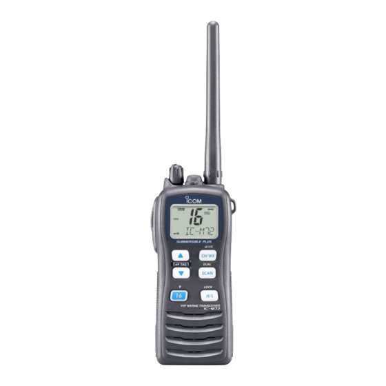
Page 10: Panel Description
PANEL DESCRIPTION ■ Front, top and side panels q VOLUME CONTROL [VOL] Turns power ON and adjusts the audio level. w PTT SWITCH [PTT] Push and hold to transmit; release to receive. e MONITOR KEY [ • Manually opens the squelch for monitoring the channel Function while pushed and held. -
Page 11: Function Display
PANEL DESCRIPTION ■ Function display y TRANSMIT POWER/LOCK KEY [H/L•LOCK] • Selects high, middle or low power when pushed. (p. 9) • Toggles the lock function ON/OFF when pushed and held for 1 sec. (p. 10) u SCAN KEY [SCAN•DUAL] •... -
Page 12: Panel Description
PANEL DESCRIPTION r MONITOR INDICATOR (p. 10) !2 W EATHER CHANNEL/WEATHER ALERT INDICATORS Appears when the monitor function is activated. (p. 8) • “WX” appears when the weather channel group is t DUALWATCH/TRI-WATCH INDICATORS (p. 16) selected. “DUAL” blinks during dualwatch; “TRI” blinks during tri- •... -
Page 13: Basic Operation
BASIC OPERATION ■ Channel selection D Channel 9 (Call channel) IMPORTANT!: Prior to using the transceiver for the first time, fully charge the battery pack. This will help maxi- Channel 9 is the leisure-use call channel. Each regular mize the capability and life of the battery. To avoid dam- channel group has separate call channels. -
Page 14: Weather Channels
Push Push for 1 sec. ✔ CONVENIENT! U.S.A. channel The IC-M72 can detect a weather aler t tone on the selected weather channel while in another channel (when the or during scanning. See the power save function is turned ON) “SET mode items”... -
Page 15: Receiving And Transmitting
To prevent accidental prolonged transmission, etc., the ➥ Push [ ] , and push [Z] to open the squelch. IC-M72 has a time-out timer function. This timer cuts a ➥ Rotate [VOL] to set the volume level. transmission OFF after 5 min. of continuous transmission. -
Page 16: Call Channel Programming
BASIC OPERATION ■ Call channel programming ■ Lock function The call channel key is used to select Channel 9 by default, This function electronically locks all keys (except for [PTT], however, you can program your most often-used channel in to prevent accidental channel changes and and [H/L•LOCK]) each channel group for quick recall. -
Page 17: Adjusting The Squelch Level
■ Adjusting the squelch level ■ Voice scrambler operation (available with some versions only) To adjust the IC-M72’s squelch level, use the [Y]/[Z] keys as desired below. In order to receive signals properly, as well D Activating the scrambler as for the scan to function effectively, the squelch must be The voice scrambler provides private communications. -
Page 18: Vox Function
The opening comment appears each VOX function ON or OFF while connecting the headset time the IC-M72 is powered ON. The comment may be up to and optional headset adapter to [SP MIC] connector. 16 characters long. -
Page 19: Basic Operation
BASIC OPERATION D Channel name/comment programming D O pening comment programming q Push [Y]/[Z] to select a channel to q W h i l e p u s h i n g a n d h o l d i n g program. -
Page 20: Scan Operation
SCAN OPERATION ■ Scan types Set the TAG channels before scanning. Scanning is an efficient way to quickly locate signals over a (scanned channel) Clear those TAG channels which are not needed or inconve- wide frequency range. The transceiver has a priority scan niently stop scanning, such as digital communications. -
Page 21: Setting Tag Channels
SCAN OPERATION ■ Setting TAG channels ■ Starting a scan For more efficient scanning, add desired channels as TAG Set the weather alert function, priority scan function, scan channels or clear the TAG for unwanted channels. resume timer and auto scan function in advance, using the Untagged will be skipped during scanning. -
Page 22: Dualwatch/Tri-Watch
DUALWATCH/TRI-WATCH ■ Description ■ Operation Dualwatch monitors Channel 16 while you are receiving q Select the desired operating channel. w Push [SCAN•DUAL] for 1 sec. to start dualwatch or tri- another channel; tri-watch monitors Channel 16 and the call channel while receiving another channel. watch (depending on the SET mode setting;... -
Page 23: Set Mode
SET MODE ■ SET mode programming D SET mode operation SET mode is used to change the condition of 18 transceiver q Turn power OFF. functions: beep tone function, weather alert function, scan w W hile pushing and holding [ ] , turn power ON to enter type, scan resume timer, auto scan function, dual/tri-watch the SET mode. -
Page 24: Set Mode Items
ON, any detected weather pauses for 5 sec. after receiving a signal and then resumes alert will make the IC-M72 activate a blinking “WXALT” alert even if the signal has been received. indicator on the function display and repeatedly sound a beep tone. -
Page 25: Auto Scan Function
SET MODE D Auto scan function D Monitor key action “ ” “ ” The auto scan function starts the desired scan automatically The monitor key action cuts off the squelch function tempo- when no signal is received, and no operation is performed rarily. -
Page 26: Lcd Contrast Selection
SET MODE D LCD contrast selection D Self check function “ ” “ ” The contrast of the LCD can be selected from Hi (default) The self check function informs you in case a problem is and Lo. found with the radio. Self check automatically and quickly runs through its diagnostic steps each time the radio is turned ON. -
Page 27: Channel Name Scroll Type
SET MODE D Battery voltage indicator D Channel name scroll type “ ” “ ” This function controls display or non-display settings of the Selects the channel name/comment scroll type from 1 and 2. connected battery pack’s voltage when the power is ON. •... -
Page 28: Set Mode
SET MODE D Voice scrambler code D VOX delay “ ” “ ” available with some versions only) Sets the VOX delay timer (0.5 to 3.0 sec. in 0.5 sec. steps) that the transceiver keeps on transmitting after you stops There are 32 codes available for programming. -
Page 29: Battery Charging
• R DANGER! NEVER incinerate a used battery pack since internal battery gas may cause a rupture or explosion. • R DANGER! Use and charge only specified Icom battery • R DANGER! NEVER solder the battery terminals, or pack with Icom transceiver. Only Icom battery pack is tested NEVER modify the battery pack. - Page 30 ±0˚C to +45˚C (+32˚F to +113˚F). pacity is about half, then keep it safely in a cool dry place Icom recommends charging the battery at +20˚C (+68˚F). with the temperature range as below; The battery may heat up or rupture if charged out of the –20˚C to +50˚C (–4˚F to +122˚F) (within a month)
-
Page 31: Supplied Battery Charger
BATTERY CHARGING ■ Supplied battery charger D Charging D BC-166 installation q Connect the AC adapter as shown below. • To a desktop • To a wall w Insert the battery pack with/without the transceiver into Supplied screws the charger. •... -
Page 32: Optional Battery Chargers
BATTERY CHARGING ■ Optional battery chargers D Rapid charging with the BC-119N+AD-114 D AD-114 installation The optional BC-119N provides rapid charging of battery q Connect both the 3-pin and 10-pin connectors of the char- packs. The following options are additionally required. ger to the AD-114 desktop charger adapter’s plug. - Page 33 BATTERY CHARGING D Rapid charging with the BC-121N+AD-114 The optional BC-121N allows up to 6 battery packs to be charged simultaneously. The following options are addition- ally required. • Six AD-114 charger adapters • An AC adapter or the DC power cable (BC-157) (OPC-656) Transceiver...
-
Page 34: Optional Swivel Belt Clip
OPTIONAL SWIVEL BELT CLIP ■ Attachment ■ Detachment q Screw the base clip to the Turn the transceiver upside down in the direction of the ➥ back of the transceiver arrow and pull out from the belt clip. Supplied screws using the two screws (sup- , as shown at right. -
Page 35: Optional Speaker-Microphone
OPTIONAL SPEAKER-MICROPHONE ■ HM-125 descriptions ■ Attachment Insert the speaker-mic connector onto the [SP MIC] con- Alligator type clip To attach the speaker-mic. nector and carefully screw it tight, as shown in the diagram to your shirt or collar, etc. below. -
Page 36: Troubleshooting
TROUBLESHOOTING PROBLEM POSSIBLE CAUSE SOLUTION REF. The transceiver does not • The battery is depleted. • Recharge the battery pack. pgs. turn ON. 25–27 • Bad connection to the battery pack. • Check the connection to the transceiver. p. 3 s o u n d f r o m t h e... -
Page 37: Vhf Marine Channel List
VHF MARINE CHANNEL LIST Channel number Frequency (MHz) Channel number Frequency (MHz) Channel number Frequency (MHz) Channel number Frequency (MHz) CAN Transmit Receive CAN Transmit Receive CAN Transmit Receive CAN Transmit Receive 156.050 160.650 157.275 161.875 19A 156.950 156.950 156.325 160.925 20 * 157.000 161.600 66A * 156.050 156.050... -
Page 38: Specifications
: 16K0G3E • Sensitivity : 0.22 µV typical (12 dB SINAD) • Power supply requirement : Specified Icom’s battery pack only • Squelch sensitivity : 0.35 µV typical (at threshold) • Current drain • Intermodulation rejection ratio : 70 dB typical (at 7.5 V DC;... -
Page 39: Options
Same as that supplied with the transceiver. D BELT CLIPS • MB-103 belt clip Icom optional equipment is designed for optimal perform- The same as supplied with the transceiver. ance when used with this transceiver. We are not respon- • MB-86... - Page 40 A-6479D-1EX-r Printed in Japan 2005–2009 Icom Inc. © 1-1-32 Kamiminami, Hirano-ku, Osaka 547-0003, Japan Printed on recycled paper with soy ink.
Need help?
Do you have a question about the IC-M72 and is the answer not in the manual?
Questions and answers