Icom IC-M71 Instruction Manual
Hide thumbs
Also See for IC-M71:
- Instruction manual (327 pages) ,
- Instruction manual (40 pages) ,
- Instruction manual (40 pages)
Table of Contents
Advertisement
Advertisement
Table of Contents

Subscribe to Our Youtube Channel
Related Manuals for Icom IC-M71


Summary of Contents for Icom IC-M71
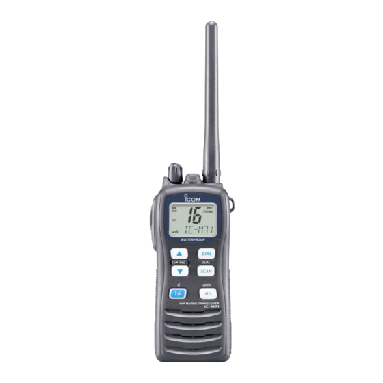
- Page 1 INSTRUCTION MANUAL VHF MARINE TRANSCEIVER iM71...
- Page 2 EN 300 698-2 V1.1.1 (2000-8) v) EN 300 698-3 V1.1.1 (2001-5) Signature vii) CE Versions of the IC-M71 which display the This warning symbol indicates that this equipment “CE” symbol on the serial number seal, comply operates in non-harmonised frequency bands...
-
Page 3: Recommendation
IN CASE OF EMERGENCY RECOMMENDATION If your vessel requires assistance, contact other vessels and CLEAN THE TRANSCEIVER THOROUGHLY WITH FRESH the Coast Guard by sending a distress call on Channel 16. WATER after exposure to saltwater, and dry it before opera- tion. -
Page 4: Foreword
Large, easy-to-read LCD With the generous dimensions of 22.5(H) × 31.5(W) mm, EXPLICIT DEFINITIONS the IC-M71’s function display is easy to read and shows operating conditions at a glance. Backlighting and con- trast can be adjusted to suit your preferences. -
Page 5: Precaution
0.9 meters away from your vessel’s magnetic navigation compass. Icom, Icom Inc. and the logo are registered trademarks of Icom Incor- porated (Japan) in the United States, the United Kingdom, Germany, France, Spain, Russia and/or other countries. -
Page 6: Table Of Contents
TABLE OF CONTENTS IN CASE OF EMERGENCY ............ii 5 SCAN OPERATION (except Dutch versions) ....14–15 I Scan types ................14 RECOMMENDATION ..............ii I Setting TAG channels ............15 FOREWORD .................. iii I Starting a scan ..............15 IMPORTANT ................... -
Page 7: Operating Rules
OPERATING RULES D Priorities (2) OPERATOR’S LICENSE A restricted Radiotelephone Operator Permit is the license • Read all rules and regulations pertaining to priorities and most often held by small vessel radio operators when a radio keep an up-to-date copy handy. Safety and distress calls is not required for safety purposes. -
Page 8: Supplied Accessories And Attachments
SUPPLIED ACCESSORIES AND ATTACHMENTS I Supplied accessories I Attachments Flexible antenna The following accessories are supplied: Qty. q Handstrap …………………………………………………… 1 Connect the supplied flexible an- tenna to the antenna connector. w Battery charger …………………………………………… 1 e Screws for the battery charger …………………... -
Page 9: Supplied Accessories And Attachments
SUPPLIED ACCESSORIES AND ATTACHMENTS D Battery pack D Belt clip q Attach the battery pack into the transceiver as below. Attach the belt clip to the transceiver as illustrated below. Supplied screws w Lock the battery pack with the latch. CAUTION!: NEVER attach or detach the battery pack when wet. -
Page 10: Panel Description
PANEL DESCRIPTION I Front, top and side panels q VOLUME CONTROL [VOL] Turns power ON and adjusts the audio level. w PTT SWITCH [PTT] Push and hold to transmit; release to receive. e MONITOR KEY [ • Manually opens the squelch for monitoring the channel while pushed and held. -
Page 11: I Function Display
PANEL DESCRIPTION I Function display y TRANSMIT POWER/LOCK KEY [H/L•LOCK] • Selects high, middle or low power when pushed. (p. 9) • Toggles the lock function ON/OFF when pushed and held for 1 sec. (p. 10) u SCAN KEY [SCAN•DUAL] •... -
Page 12: Panel Description
PANEL DESCRIPTION r MONITOR INDICATOR (p. 10) !2 CHANNEL GROUP INDICATOR (p. 8) Appears when the monitor function is activated. “USA*” appears when U.S.A.; “INT” appears when Inter- national channel group is selected. t DUALWATCH/TRI-WATCH INDICATORS (p. 16) *Available with the UK versions only. “DUAL”... -
Page 13: Basic Operation
BASIC OPERATION I Channel selection D Call channel IMPORTANT!: Prior to using the transceiver for the first time, fully charge the battery pack. This will help maximize Call channel is the leisure-use call channel. Each regular the capability and life of the battery. To avoid damage to channel group has separate call channels. - Page 14 BASIC OPERATION D U.S.A., International and ATIS channels The IC-M71 has U.S.A.,* International and ATIS † channels. You must select the proper channels for the operating area. *Available with the UK versions only. † Available with the German and Dutch versions only.
-
Page 15: I Receiving And Transmitting
BASIC OPERATION I Receiving and transmitting IMPORTANT: To maximize the readability of your trans- CAUTION: Transmitting without an antenna may mitted signal, pause a second after pushing [PTT], hold damage the transceiver. the microphone 5 to 10 cm from your mouth, and speak into the microphone using a normal voice level. -
Page 16: I Call Channel Programming
BASIC OPERATION I Call channel programming I Lock function The call channel key is used to select Channel 16 by default This function electronically locks all keys (except for [PTT], [ , however, you can program your most to prevent accidental channel changes and (depending on versions) and [H/L•LOCK]) often-used channel in each channel group for quick recall. -
Page 17: I Adjusting The Squelch Level
I Adjusting the squelch level I Voice scrambler operation (available with some versions only) To adjust the IC-M71’s squelch level, use the [Y Y ]/[Z Z ] keys as desired below. In order to receive signals properly, as well as D Activating the scrambler for the scan to function effectively, the squelch must be ad- The voice scrambler provides private communications. -
Page 18: I Vox Function
The opening comment appears each VOX function ON or OFF while connecting the headset time the IC-M71 is powered ON. The comment may be up to and optional headset adapter to [SP MIC] connector. 16 characters long. -
Page 19: Basic Operation
BASIC OPERATION D D Channel name/comment programming D D Opening comment programming q Push [Y Y ]/[Z Z ] to select a channel to q While pushing holding program. [SCAN•DUAL], turn power ON. • Push and hold [DIAL] for 1 sec. to select •... -
Page 20: Scan Operation (Except Dutch Versions)
SCAN OPERATION (except Dutch versions) I Scan types Scanning is an efficient way to quickly locate signals over a Set the TAG channels before scanning. (scanned channel) wide frequency range. The transceiver has a priority scan set- Clear those TAG channels which are not needed or inconve- ting and normal scan setting. -
Page 21: I Setting Tag Channels
SCAN OPERATION I Setting TAG channels I Starting a scan For more efficient scanning, add desired channels as TAG Set the priority scan function, scan resume timer and auto channels or clear the TAG for unwanted channels. scan function in advance, using the SET mode. (pgs. -
Page 22: Dualwatch/Tri-Watch (Except Dutch Versions)
DUALWATCH/TRI-WATCH (except Dutch versions) I Description I Operation q Select the desired operating channel. Dualwatch monitors Channel 16 while you are receiving w Push [SCAN•DUAL] for 1 sec. to start dualwatch or tri- another channel; tri-watch monitors Channel 16 and the call channel while receiving another channel. -
Page 23: Set Mode
SET MODE I SET mode programming D SET mode operation SET mode is used to change the condition of 17 transceiver q Turn power OFF. functions: beep tone function, scan type, scan resume timer, w While pushing and holding [ ], turn power ON to enter auto scan function, dual/tri-watch function, monitor key action, the SET mode. -
Page 24: I Set Mode Items
SET MODE I SET mode items D Beep tone function “ ” D Scan resume timer “ ” Selects the key touch beep sound ON or US, or turns sound (except Dutch versions) OFF. The scan resume timer can be set as a pause (OFF) or timer •... -
Page 25: Backlight Function
SET MODE D Dual/Tri-watch function D Backlight function “ ” “ ” This function is convenient for night-time operation. The back- (except Dutch versions) light can be selected from ON and OFF. This item selects dual or tri-watch as desired. See p. 16 for •... - Page 26 SET MODE D Auto power save function D Self check function “ ” “ ” The auto power save function reduces current drain by deac- The self check function informs you in case a problem is tivating the receiver circuit for preset intervals. found with the radio.
-
Page 27: Channel Name Scroll Type
SET MODE D Battery voltage indicator D Channel name scroll type “ ” “ ” This function controls display or non-display settings of the Selects the channel name/comment scroll type from 1 and 2. connected battery pack’s voltage when the power is ON. •... -
Page 28: Set Mode
SET MODE D D Voice scrambler code D VOX delay “ ” “ ” available with some versions only) Sets the VOX delay timer (0.5 to 3.0 sec. in 0.5 sec. steps) that the transceiver keeps on transmitting after you stops There are 32 codes available for programming. -
Page 29: Battery Charging
• R DANGER! NEVER incinerate a used battery pack since internal battery gas may cause a rupture or explosion. • R DANGER! Use and charge only specified Icom battery • R DANGER! NEVER solder the battery terminals, or pack with Icom transceiver. Only Icom battery pack is tested NEVER modify the battery pack. - Page 30 • CAUTION! DO NOT charge the battery outside of the spec- half-capacity, then keep it safely in a cool dry place with the ified temperature range: ±0˚C to +45˚C. Icom recommends temperature between –20˚C to +25˚C. charging the battery at +20˚C. The battery may heat up or rupture if charged out of the specified temperature range.
-
Page 31: I Supplied Battery Charger
BATTERY CHARGING I Supplied battery charger D BC-166 installation D Charging q Connect the AC adapter as shown below. • To a desktop • To a wall w Insert the battery pack with/without the transceiver into the Supplied screws charger. •... -
Page 32: I Optional Battery Chargers
BATTERY CHARGING I Optional battery chargers D AD-114 installation D Rapid charging with the BC-119N+AD-114 qConnect both the 3-pin and 10-pin connectors of the The optional BC-119N provides rapid charging of battery charger to the AD-114 desktop charger adapter’s plug. packs. - Page 33 BATTERY CHARGING D Rapid charging with the BC-121N+AD-114 The optional BC-121N allows up to 6 battery packs to be charged simultaneously. The following options are addition- ally required. • Six AD-114 charger adapters • An AC adapter or the DC power cable (BC-157) (OPC-656) Transceiver...
-
Page 34: Optional Swivel Belt Clip
OPTIONAL SWIVEL BELT CLIP I Attachment I Detachment ➥ q Screw the base clip to the Turn the transceiver upside down in the direction of the back of the transceiver arrow and pull out from the belt clip. Supplied screws using the two screws (sup- , as shown at right. -
Page 35: Optional Speaker-Microphone
OPTIONAL SPEAKER-MICROPHONE I HM-125 descriptions I Attachment Insert the speaker-mic connector onto the [SP MIC] connec- Alligator type clip tor and carefully screw it tight, as shown in the diagram To attach the speaker-mic. below. Be careful not to cross-thread the connection. to your shirt or collar, etc. -
Page 36: Troubleshooting
TROUBLESHOOTING PROBLEM POSSIBLE CAUSE SOLUTION REF. The transceiver does not • The battery is depleted. • Recharge the battery pack. pgs. turn ON. 25–27 • Bad connection to the battery pack. • Check the connection to the transceiver. p. 3 sound from •... -
Page 37: Vhf Marine Channel List
VHF MARINE CHANNEL LIST • International channels Frequency (MHz) Frequency (MHz) Frequency (MHz) Frequency (MHz) Frequency (MHz) Frequency (MHz) Transmit Receive Transmit Receive Transmit Receive Transmit Receive Transmit Receive Transmit Receive 156.050 160.650 156.550 156.550 157.050 161.650 156.125 160.725 156.625 156.625 157.125 161.725... -
Page 38: Specifications
: 16K0G3E • Sensitivity : –2 dBµ emf typical (20 dB SINAD) • Power supply requirement : Specified Icom’s battery pack only • Squelch sensitivity : –6 dBµ emf typical (at threshold) • Current drain • Intermodulation rejection ratio: 68 dB (at 7.2 V DC;... -
Page 39: Options
OPTIONS D BATTERY CASE AND PACK D DC CABLES • BP-245 • CP-17L Li-Ion BATTERY PACK CIGARETTE LIGHTER CABLE 7.4 V/2000 mAh Li-Ion battery pack. Charges the battery pack through a 12 V cigarette lighter socket. (For BC-119N) • OPC-515L/OPC-656 DC POWER CABLES D CHARGERS Charges the battery pack using 13.8 V power source instead of the... - Page 40 <Intended Country of Use> A-6480D-1EU-w Printed in Japan 1-1-32 Kamiminami, Hirano-ku, Osaka 547-0003, Japan 2006 Icom Inc. ©...
Need help?
Do you have a question about the IC-M71 and is the answer not in the manual?
Questions and answers