Table of Contents
Advertisement
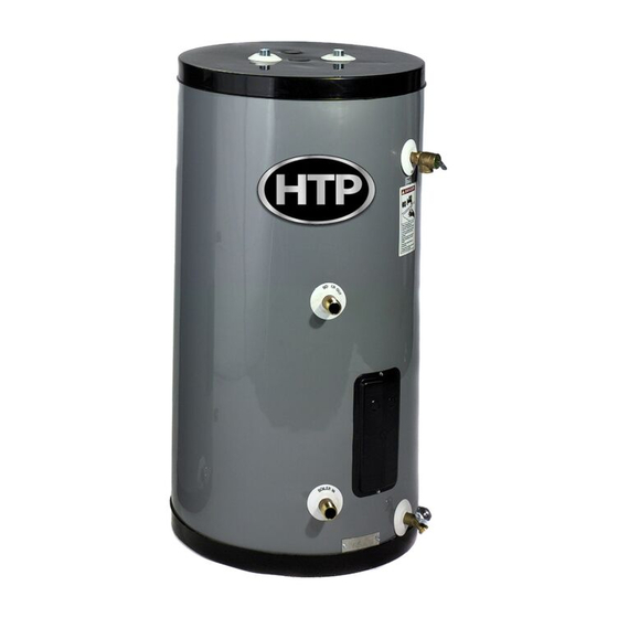
SuperStor Contender
Indirect Fired
Water Heater
INSTALLATION
START-UP
MAINTENANCE
PARTS
SuperStor Contender
Water Heater Models
SSC-35 / SSC-50 / SSC-80 / SSC-119*
*NOTE: A suffix of "S" denotes Solar Model
NOTICE: HTP reserves the right to make product changes or updates without notice and will not be held liable for
typographical errors in literature.
NOTE TO CONSUMER: PLEASE KEEP ALL INSTRUCTIONS FOR FUTURE REFERENCE.
120 Braley Rd. P.O. Box 429
East Freetown, MA 02717-0429
www.htproducts.com
LP-65 Rev. 1.30.12
Advertisement
Table of Contents

Summary of Contents for HTP SSC-35
- Page 1 SSC-35 / SSC-50 / SSC-80 / SSC-119* *NOTE: A suffix of “S” denotes Solar Model NOTICE: HTP reserves the right to make product changes or updates without notice and will not be held liable for typographical errors in literature. NOTE TO CONSUMER: PLEASE KEEP ALL INSTRUCTIONS FOR FUTURE REFERENCE.
-
Page 2: For The Installer
The following defined terms are used throughout this manual to bring attention to the presence of hazards of various risk levels, or to important product information. DANGER indicates an imminently hazardous situation which, if not avoided, will result in death or serious injury. WARNING indicates a potentially hazardous situation which, if not avoided, could result in death or serious injury. -
Page 3: Table Of Contents
PART 4 – HEATER CONTROL AND WIRING ....................... 16 A. CONTROL ..................................16 B. WIRING ..................................... 16 PART 5 – OPERATING THE HEATER ........................16 PART 6 – MAINTENANCE AND TROUBLESHOOTING ..................17 HTP CUSTOMER INSTALLATION RECORD FORM ..................20... -
Page 4: Part 1 - General Safety Information
PART 1 – GENERAL SAFETY INFORMATION A. PRECAUTIONS This water heater is approved for indoor installations only. Clearance to combustible materials: 0” top, bottom, sides and back. Heater must have room for service: 24” front and 6” sides are minimum recommended service clearances. -
Page 5: Specifications And Performance Ratings
Remove all sides of the shipping crate to allow the heater to be moved into its installation location. A. SPECIFICATIONS AND PERFORMANCE RATINGS Figure 1 – Specifications and Dimensions... -
Page 6: Performance And Sizing Guidelines
Locate the water heater where any leakage from the relief valve, related piping, tank, or connections will not result in damage to surrounding areas or lower floors of the building. The water heater should be located near a floor drain, or installed in a drain pan. HTP WILL NOT be held liable for leakage damages. Figure 2 If you do not provide the minimum clearances shown, it might not be possible to service the heater without removing it from the space. -
Page 7: Anode Rod
This water heater must not be located near flammable liquids such as gasoline, butane, liquefied propane, adhesives, solvents, paint thinners, etc., as the controls of this water heater could ignite these vapors and cause an explosion, resulting in property damage, severe personal injury, or death. D. -
Page 8: Cold Water Inlet
In a steam boiler, the tank supply must be connected to the boiler well below the minimum water level. A strainer and drain valve should be installed at the boiler for periodic draining of scale and sludge. Banging and steam bound traps will occur if the boiler water supplied to the heat exchanger has steam or is slightly above the low water cut off. -
Page 9: Temperature And Pressure Relief Valve
Table 2 details the relationship of water temperature and time with regard to scald injury and may be used as a guide in determining the safest water temperature for your applications. E. TEMPERATURE AND PRESSURE RELIEF VALVE A factory installed temperature and pressure relief valve long element, meeting the requirements for relief valves for hot water heaters ANSI Z21.22B / CSA 4.4-M99, has been installed for your safety and convenience. -
Page 10: Potable Expansion Tank
PRESSURE DROP FOR PIPE LENGTH OF 1” COPPER, AND FOR SIX 90 ELBOWS, AND ON TEE ON THE 20’ 30’ 40’ 50’ 60’ PIPE SIZE SSC-35 8 GPM 6.28 6.53 6.78 6.28 7.28 SSC-50 8 GPM 6.48... -
Page 11: Installation Diagrams
I. INSTALLATION DIAGRAMS Figure 3... - Page 12 Figure 4...
- Page 13 Figure 5...
- Page 14 Figure 6...
- Page 15 Figure 7...
-
Page 16: Part 4 - Heater Control And Wiring
PART 4 – HEATER CONTROL AND WIRING A. CONTROL A surface mounted control is provided and mounted inside of the control access compartment. There is an insulation blanket under the control access cover to ensure accurate readings of water temperature. The control is factory set at 120 F for your safety (see scald danger warning above). -
Page 17: Part 6 - Maintenance And Troubleshooting
PART 6 – MAINTENANCE AND TROUBLESHOOTING Periodic maintenance should be performed by a qualified service technician to assure that all the equipment is operating safely and efficiently. The owner should make necessary arrangements with a qualified heating con- tractor for periodic maintenance of the heater. Installer must also inform the owner that the lack of proper care and maintenance of the heater may result in a hazardous condition. - Page 18 TROUBLESHOOTING HOT WATER HAS A ROTTEN EGG ODOR PROBLEM POSSIBLE SOLUTION Check with water quality specialist in your area. Have water Supply water has high sulfate or mineral content supply analyzed. Address water quality issues according to specialist’s recommendations. NO HOT WATER PROBLEM POSSIBLE SOLUTION Zone valve not opening...
- Page 19 Figure 8 – Parts Blowout...
-
Page 20: Htp Customer Installation Record Form
Customer: Please only sign after the installer has reviewed the installation, safety, proper operation, and maintenance of the system. In the case that the system has any problems, please call the installer. If you are unable to make contact, please contact your HTP Sales Representative. Distributor/Dealer: Please insert contact details.


Need help?
Do you have a question about the SSC-35 and is the answer not in the manual?
Questions and answers