Table of Contents
Advertisement
Quick Links
Installation
Start-Up
Maintenance
Parts
Warranty
For Residential and
Commercial Use
DB Series and DBX Models*
*A suffix of "X" denotes models with
internal heat exchanger
This manual must only be used by a qualified installer /
service technician. Read all instructions in this manual
before installing. Perform steps in the given order.
Failure to do so could result in substantial property
damage, severe personal injury, or death.
NOTE TO CONSUMER: PLEASE KEEP ALL INSTRUCTIONS FOR FUTURE REFERENCE.
272 Duchaine Blvd.
Drain Back Tank
HTP reserves the right to make product changes or
updates without notice and will not be held liable for
typographical errors in literature.
The surfaces of these products contacted by potable
(consumable) water contain less than 0.25% lead by weight
as required by the Safe Drinking Water Act, Section 1417.
New Bedford, MA 02745
www.htproducts.com
lp-351b Rev. 11.25.15
Advertisement
Table of Contents

Related Manuals for HTP DB Series


Summary of Contents for HTP DB Series
- Page 1 *A suffix of “X” denotes models with internal heat exchanger HTP reserves the right to make product changes or This manual must only be used by a qualified installer / updates without notice and will not be held liable for service technician.
-
Page 2: Table Of Contents
Part 2 - Important Information commanding officer or departmental official may be the AHJ. A. Piping NOTE: HTP, Inc. reserves the right to modify product technical B. Sizing the Drain Back Tank specifications and components without prior notice. C. Locating the Solar Water Heater D. -
Page 3: Introduction
Part 4 - Start-Up Preparation A. Fill the Drain Back Reservoir DO NOT USE THE SOLAR SYSTEM IF ANY PART HAS BEEN B. Start-Up Procedure SUBMERGED IN WATER. Immediately call a qualified service Part 5 - Service / Maintenance Procedures technician. -
Page 4: When Servicing The Solar Water Heating System
A. When Servicing the Solar Water Heating System Approximate Time / Temperature Relationships in Scalds To avoid electric shock, disconnect electrical supply before More than 5 minutes performing maintenance. 1 1/2 to 2 minutes To avoid severe burns, allow solar collector and associated About 30 seconds equipment to cool before servicing. -
Page 5: Part 2 - Important Information
FDA rated as “generally recognized as safe” (GRAS). The recommended glycol is DOWFROST or equivalent. Using proper concentrations of glycol, solar systems can be operated at ambient temperatures as low as -60 F. Freeze tolerance limits are based upon an assumed set of environmental conditions. -
Page 6: Specifications And Dimensions
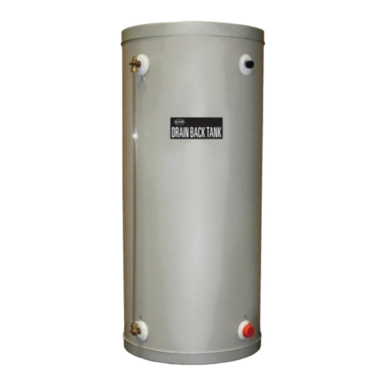
D. Specifications and Dimensions Figure 3 - Drain Back Tank without Heat Exchanger Specifications and Dimensions lp-351b Rev. 11.25.15... - Page 7 Figure 4 - Drain Back Tank with Heat Exchanger Specifications and Dimensions lp-351b Rev. 11.25.15...
-
Page 8: Part 3 - Piping
b. Pipe drain back tank outlet to the solar collector supply Part 3 - Piping fitting. The design and installation of the solar water heating system c. Pipe cold supply water from the solar storage tank to the should be done by qualified individuals. It is important that heat exchanger inlet fitting located on the drain back tank. -
Page 9: Electrical Installation
50%, unless the manufacture specifies that a different to install the included snap fittings ratio is recommended for use with solar water heaters. HTP into the tank with the included 6 X recommends using a pre-blended solution. Glycol/water mix 1 screws. -
Page 10: Applications
G. Applications Figure 8 - Drain Back Tank without Heat Exchanger FIGURE NOTES: 1. This drawing is meant to demonstrate system piping concept only. The installer is responsible for all equipment and detailing by local codes. 2. Non-potable HTF shall only be used for the solar heat exchanger circuit. Never introduce non-potable HTF to any connection other than the solar loop. -
Page 11: Part 4 - Start-Up Preparation
Figure 9 - Drain Back Tank with Heat Exchanger FIGURE NOTES: 1. This drawing is meant to demonstrate system piping concept only. The installer is responsible for all equipment and detailing by local codes. 2. Non-potable HTF shall only be used for the solar heat exchanger circuit. Never introduce non-potable HTF to any connection other than the solar loop. -
Page 12: Start-Up Procedure
the plug on the solar controller and call a plumber. B. Other Problems Take care not to overfill the drain back solar system. Overfilling A noisy pump could be an indication of worn bearings, will cause a potentially dangerous condition that could lead to obstructions, or a leak in your system. -
Page 13: Limited Warranty
8. Connecting materials other than copper, brass, or stainless C. If HTP is unable to repair or replace the drain back tank so as steel. (Use of galvanized piping or dielectric unions is expressly to conform to this warranty after a reasonable number of attempts, forbidden.) - Page 14 ORIGINAL PURCHASER ONLY. NO OTHER WARRANTIES Your HTP warranty gives you specific legal rights, and you may also have other rights that vary from state to state. Some states do not allow the exclusion or limitation of incidental or consequential damages so this limitation or exclusion may not apply to you.
-
Page 15: Customer Installation Record Form
Customer Installation Record Form The following form should be completed by the installer for you to keep as a record of the installation in case of a warranty claim. After reading the important notes at the bottom of the page, please also sign this document. Customer’s Name Date of Installation Installation Address...
Need help?
Do you have a question about the DB Series and is the answer not in the manual?
Questions and answers