Table of Contents
Advertisement
Quick Links
Installation & Operation Manual
This appliance may be installed in an aftermar-
ket, permanently located manufactured home
(USA only) or in a mobile home, where not pro-
hibited by local codes.
This appliance is for use only with the type of
gas indicated on the rating plate. This appli-
ance is not convertible for use with other gases,
unless a certified conversion kit is used.
Report # 361-S-04-5
INSTALLER: Leave this manual with the appliance.
CONSUMER: Retain this manual for future reference.
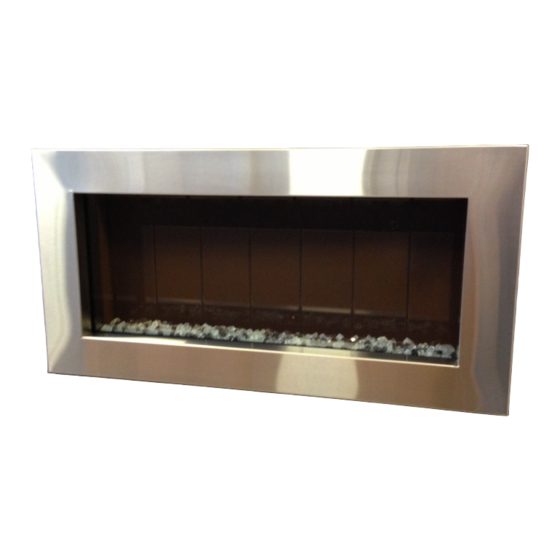
This manual specifies the installation and operation
requirements for the Solas Direct Vent Gas Fire-
place Insert Model Nos. FIN-36N, FIN-36P.
For installation into a Masonry or Factory Built
(Metal) Wood-Burning Fireplace.
WARNING: If the information in these in-
structions is not followed exactly, a fire or ex-
plosion may result causing property damage,
personal injury or loss of life.
Do not store or use gasoline or other flamma-
ble vapors and liquids in the vicinity of this or
any other appliance.
WHAT TO DO IF YOU SMELL GAS
Do not try to light any appliance.
Do not touch any electrical switch; do not
use any phone in your building.
Immediately call your gas supplier from a
neighbor's phone. Follow the gas sup-
plier's instructions.
If you cannot reach your gas supplier, call
the fire department.
Installation and service must be performed by
a qualified installer, service agency or the gas
supplier.
Young children should be carefully supervised when
they are in the same room as the appliance. Tod-
dlers, young children and others may be susceptible
to accidental contact burns. A physical barrier is
recommended if there are at risk individuals in the
house. To restrict access to a fireplace or stove, in-
stall an adjustable safety gate to keep toddlers,
young children and other at-risk individuals out of
the room and away from hot surfaces.
Advertisement
Table of Contents

Related Manuals for Solas FIN-36N


Summary of Contents for Solas FIN-36N
- Page 1 Installation & Operation Manual This manual specifies the installation and operation requirements for the Solas Direct Vent Gas Fire- place Insert Model Nos. FIN-36N, FIN-36P. For installation into a Masonry or Factory Built (Metal) Wood-Burning Fireplace. WARNING: If the information in these in-...
- Page 2 : Assurez-vous de bien suivre AVERTISSEMENT les instructions données dans cette notice pour réduire au minimum le risque d’incindie ou d’explosion ou pour éviter tout dommage matériel, toute blessure ou la mort. Ne pas entreposer ni utilizer d’essence ni d’autres vapeurs ou liquides inflammables dans le voisinage de cet appareil ou de tout autre appareil.
-
Page 3: Table Of Contents
WARRANTY INFORMATION WE STRONGLY SUGGEST THAT YOU READ THIS MANUAL THOROUGHLY BEFORE BE- GININNG THE INSTALLATION OF THE SOLAS DIRECT VENT GAS FIREPLACE INSERT. ALTHOUGH THE BASIC REQUIREMENTS FOR THE INSTALLATION OF ALL DIRECT VENT GAS FIREPLACES INSERTS ARE SIMILAR, EACH SPECIFIC PRODUCT HAS ITS OWN UNIQUE SET-UP AND INSTALLATION REQUIREMENTS THAT MUST BE FOL- LOWED EXACTLY. -
Page 4: Important Safety Information
IMPORTANT SAFETY INFORMATION The installation must conform with local codes or, in the absence of local codes, with the National Fuel Gas Code, ANSI Z223.1/NFPA 54, or the Canadian Installation Code, CAN/CSA B149.1. A manufactured home (USA only) or mobile home OEM installation must conform with the Manufactured Home Construction and Safety Standard, Title 24 CFR, Part 3280 or when such a standard is not applica- ble, the Standard for Manufactured Home Installations, ANSI/BCSBCS A225.1, or Standard for Gas Equipped Recreational Vehicles and Mobile Housing, CSA Z240.4. -
Page 5: Specifications
Altitudes and CSA P.4.1-09. The Solas Fireplace Insert is approved for installation at elevations up to 2000 feet in the U.S. and 1370 me- ters (4500 feet) in Canada without change. If your installation is at an elevation greater than these, consult with the local authority having jurisdiction for gas product installations to determine their specific require- ments for high altitude installations. -
Page 6: Installation Requirements
For tight fits (under 24") see the section Width. 29.75” - "Removing the “Vent Connector" See Page additional space may be required for gas line instal- lation. The Solas Fireplace Insert inserts 14.75" deep into the Fireplace cavity. Surround Size Options: Standard: 26”H x 38”W Medium: 29”H x 40”W... -
Page 7: Massachusetts Requirements
INSTALLATION REQUIREMENTS Factory-Built (Metal) Wood-Burning Fireplace Requirements NOTE: Any parts that are removed must be removed in a way that would allow them to be re-installed if the insert is ever removed (removal of rivets or screws is acceptable). The damper ("A") and grate (with log set) ("B") must be removed (see the illustration below) The smoke shelf ("C"), internal baffles ("D"), screen ("E"), masonry lining or refractory ("G"... -
Page 8: Installation Requirements
INSTALLATION REQUIREMENTS Hearth Requirements The heater and face must not contact any combustible surfaces. A minimum 1” clearance to a combustible floor is required. A non-combustible hearth extension is not required. However, if the heater is installed close to the floor, we recommend a hearth to protect the flooring surface from discoloration or other negative impact from the heater. -
Page 9: Assembly & Installation
WARNING: Failure to position the parts in accordance with the diagrams shown on pages 9 thru 18 of this manual, or failure to use the parts specifically approved with the appliance may result in property damage, or personal injury. UNPACKING THE SOLAS FIREPLACE INSERT The fireplace components are shipped in two car- tons, The crate contains the fireplace insert, and the carton contains the surround you have selected. -
Page 10: Venting
Confirm any planned changes with local building of- ficials. Use Only Approved Venting Observe local codes when venting the Solas Fireplace Insert. If no local codes exist, follow ANSI Z21.88-2009 installation code. Please consult the installation instructions supplied by the venting manufacturer you are using. - Page 11 VENTING Use Only Approved Venting This appliance has been tested and is listed for installation with Simpson Duravent Duraflex AL venting components. The warranty will be voided, and serious fire, health, or other safety hazards may result from any of the following actions: •...
- Page 12 Feed chimney liners down the chimney and through the Air Intake Exhaust damper. Position the Solas Fireplace Insert in front of the fire- place opening to prepare for Installation. Removable Venting Connector Plate Vent Restrictors The Solas Fireplace Insert is...
-
Page 13: Venting
VENTING / INSTALLATION If you determine that a restrictor is required in your installation, place either the “E” or “F” restrictor into the exhaust port of the fireplace insert body PRIOR to reconnecting the Vent Connector Plate to the insert body as shown: Exhaust Air Intake... -
Page 14: Electrical Requirement
ASSEMBLY & INSTALLATION ELECTRICAL WIRING This fireplace insert requires 110V AC electrical supply for normal operation in order to power up the Igni- tion Control Module that is required to operate the Remote Control. However, during a power outage situa- tion, its electronic system (Ignition Control) can temporarily be powered with 4 AA batteries. - Page 15 ASSEMBLY & INSTALLATION Once the gas connection and electrical hook up have been complete you can start to process of connecting the venting to the insert body, and pushing the insert into the fireplace cavity. Locate the Vent Connector Plate locking bar and pull it forward until you can align the plate with its locating track on the top of the insert body.
- Page 16 ASSEMBLY & INSTALLATION Placing the Burner Glass Media In order to place he glass media on the burner assembly, you will need to remove the glass front from the unit. Glass Front removal: The glass front is retained by four springloaded glass retaining clips. Pull each of these clips forward, rotating 180 degrees as you do so.
- Page 17 ASSEMBLY & INSTALLATION The burner glass media poly-bag that you set aside when you unpacked the fireplace contains the correct amount of glass material to cover the burner. The entire contents of the bag should be evenly distributed over the burner tray. 1.
- Page 18 ASSEMBLY & INSTALLATION Installing Convection Air Ducts: With the front glass panel fitted, you now need to install the two convection air ducts tat were shipped in the accessory box with the fireplace insert. Align the top of the duct with the air channel on the top of the insert.
-
Page 19: Lighting And Operation
LIGHTING AND OPERATION LIGHTING THE FIRE FOR YOUR SAFETY READ BEFORE LIGHTING WARNING: If you do not follow these instructions exactly, a fire or explosion may result causing property damage, personal injury or loss of life. CAUTION: Do not operate with the glass front removed, cracked, or broken. Replacement of the glass should be done by a licensed qualified service person. -
Page 20: Operating Instructions
If the pilot flames do not resemble those in the adjacent illus- tration, contact your gas service technician or Solas dealer. After the main burner has been in operation for a few minutes, the flames should look like those in the illustration below. - Page 21 LIGHTING AND OPERATION Not all features available on the SIT Proflame 2 Remote are relevant to NOTE: the Solas Fireplace Insert. Only the features relevant to this product are dis- cussed below.
- Page 22 LIGHTING AND OPERATION...
- Page 23 LIGHTING AND OPERATION...
- Page 24 LIGHTING AND OPERATION...
- Page 25 LIGHTING AND OPERATION...
- Page 26 LIGHTING AND OPERATION...
-
Page 27: Maintenance
MAINTENANCE A qualified service agency should conduct an annual inspection and maintenance of your Solas Fireplace Insert including the overall installation and venting to keep it running safely. The following procedures should be performed only by a qualified service person. The gas supply should be turned off and the stove should be completely cool whenever a maintenance procedure is performed. - Page 28 17 of this manual when replacing the burner media on the burner top. Air Flow The Solas Fireplace Insert utilizes a convection air blower to maximize heat delivered from the fireplace. It is important that air flows freely through the convection air system and out the top of the raised section of the surround.
-
Page 29: Maintenance Log Forms
MAINTENANCE LOG We strongly recommend that you keep a log of the regular maintenance that is performed on your fireplace. We have provided the forms below to make it easy. Simply ask your qualified service per- son to fill out one of the maintenance record forms below, each time the fireplace is serviced. This will help insure that all of the required maintenance procedures have been completed, at least annu- ally. -
Page 30: Replacement Parts List
REPLACEMENT PARTS LIST For replacement parts and customer service, contact your Solas Fireplace dealer or: Hearth Innovations Inc. 4 Technology Drive Suite 5 West Lebanon, NH 03784 Telephone: 603-298-5169 Sales@hearthinnovations.com... -
Page 31: Control Schematic
CONTROL SCHEMATIC Caution: Label all wires prior to disconnection when servicing the controls. Wiring errors can cause improper and dangerous operation. Verify proper operation after servicing. -
Page 32: Installation Record Form
INSTALLATION RECORD The installer should complete the form below that describes the details of the installation. Having this writ- ten record of installation information available will greatly expedite trouble-shooting should any problem arise with your stove. The installer should keep a duplicate of this form for their records. -
Page 33: Warranty Information
Warranty... - Page 34 Manufactured by: Progressive Manufacturing Inc. 4 Technology Drive Suite 5 West Lebanon, NH 03784 www.hearthinnovations.com V2/ 8.15.2013...
Need help?
Do you have a question about the FIN-36N and is the answer not in the manual?
Questions and answers