Table of Contents
Advertisement
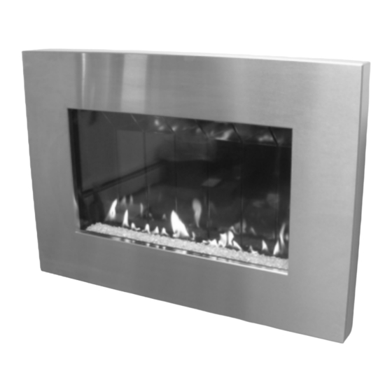
Installation & Operation Manual
This appliance may be installed in an aftermar-
ket, permanently located manufactured home
(USA only) or in a mobile home, where not pro-
hibited by local codes.
This appliance is for use only with the type of
gas indicated on the rating plate. This appli-
ance is not convertible for use with other gases,
unless a certified conversion kit is used.
Ce manual est disponsible en Français sur demande.
Report # 361-F-01-5
INSTALLER: Leave this manual with the appliance.
CONSUMER: Retain this manual for future reference.
This manual specifies the installation and opera-
tion requirements for the
Nos. SL-26N, SL-26P.
WARNING: If the information in these in-
structions is not followed exactly, a fire or
explosion may result causing property dam-
age, personal injury or loss of life.
- Do not store or use gasoline or other flam-
mable vapors and liquids in the vicinity of this
or any other appliance.
WHAT TO DO IF YOU SMELL GAS
Do not try to light any appliance.
Do not touch any electrical switch; do not
use any phone in your building.
Immediately call your gas supplier from a
neighbor's phone. Follow the gas sup-
plier's instructions.
If you cannot reach your gas supplier, call
the fire department.
- Installation and service must be performed by
a qualified installer, service agency or the gas
supplier.
Fireplace Model
Advertisement
Table of Contents

Related Manuals for Solas SL-26N


Summary of Contents for Solas SL-26N
- Page 1 Installation & Operation Manual This manual specifies the installation and opera- tion requirements for the Fireplace Model Nos. SL-26N, SL-26P. WARNING: If the information in these in- structions is not followed exactly, a fire or explosion may result causing property dam- age, personal injury or loss of life.
- Page 2 : Assurez-vous de bien suivre AVERTISSEMENT les instructions données dans cette notice pour réduire au minimum le risque d’incindie ou d’explosion ou pour éviter tout dommage matériel, toute blessure ou la mort. Ne pas entreposer ni utilizer d’essence ni d’autres vapeurs ou liquides inflammables dans le voisinage de cet appareil ou de tout autre appareil.
-
Page 3: Table Of Contents
INSTALLATION RECORD FORM WE STRONGLY SUGGEST THAT YOU READ THIS MANUAL THOROUGHLY BEFORE BE- GININNG THE INSTALLATION OF THE SOLAS DIRECT VENT GAS FIREPLACE. AL- THOUGH THE BASIC REQUIREMENTS FOR THE INSTALLATION OF ALL DIRECT VENT GAS FIREPLACES ARE SIMILAR, EACH SPECIFIC PRODUCT HAS ITS OWN UNIQUE SET- UP AND INSTALLATION REQUIREMENTS THAT MUST BE FOLLOWED EXACTLY. -
Page 4: Important Safety Information
IMPORTANT SAFETY INFORMATION The installation must conform with local codes or, in the absence of local codes, with the National Fuel Gas Code, ANSI Z223.1 or the Canadian Installation Code, CAN/CGA B149. A manufactured home (USA only) or mobile home OEM installation must conform with the Manufactured Home Construction and Safety Standard, Title 24 CFR, Part 3280 or when such a standard is not applica- ble, the Standard for Manufactured Home Installations, ANSI/BCSBCS A225.1, or Standard for Gas Equipped Recreational Vehicles and Mobile Housing, CSA Z240.4. -
Page 5: Specifications
SPECIFICATIONS INPUT Natural Gas Propane (LP) Input Rating-Btu/hr 19,000 19,000 Min. Input-Btu/hr 11,000 11,000 Orifice-DMS 5/64” GAS SUPPLY Manifold Pressure 4.8”w.c. / 1.2kPa 10.0”w.c. / 2.5kPa Min. Supply Pressure 5.5”w.c. / 1.4kPa 11.0”w.c. / 2.8kPa Max. Supply Pressure 10.0”w.c. / 2.5kPa 13.0”w.c. -
Page 6: Installation Requirements
INSTALLATION REQUIREMENTS Several issues must be addressed when selecting a suitable location for your fireplace. The minimum clearances to combustible construction are listed below. In addition, access to the gas supply must be con- sidered. The location of the fireplace will also affect the venting requirements and you must be certain the location will allow compliance with the venting requirements shown on page You must also insure that your installation provides adequate accessibility clearance for servicing and proper operation. -
Page 7: Massachusetts Requirements
INSTALLATION REQUIREMENTS The gas fireplace is shipped with a plugged 3/8” NPT connection. The gas supply piping should have a separate gas shutoff valve and a 1/8” NPT plugged tapping upstream of the valve. The stove and its main control valve must be disconnected from the gas supply piping system during any pressure testing of that system at test pressures in excess of 1/2 psi (3.5 kPa). -
Page 8: Venting
VENTING Direct Vent Gas Fireplace has been tested and listed for installation with 4” X 6 5/8” Simpson ® ® DuraVent GS/Pro Selkirk Direct-Temp , Security Secure Vent™, AmeriVent Direct™ Metal Fab Direct Vent t venting components. Although you may use the pipe components (straight pipe, el- and ICC EXCELDirec bows, etc.) from any of the listed manufacturers, you may only use the vent terminations (caps) listed in the chart on page 9. - Page 9 USING THE VENTING CHARTS The location of the vent termination must meet the requirements of the current edition of ANSI Z223.1/ NFPA 54, National Fuel Gas Code or CAN B419.1, Natural Gas and Propane Installation Code and the requirements shown on page 15 of this manual. Just as with any other vented device, vertical vent rise creates draft (negative pressure) in the firebox as the exhaust gases heat up.
- Page 10 NATURAL GAS VENTING CHART AIR RESTRICTOR EXHAUST RESTRICTOR 1— 6 TABS OPEN A or B NU = NOT USED NU = NOT USED VERTICAL TERMINA- TIONS NOT ALLOWED VERTICAL RISE IN FEET...
- Page 11 LP GAS VENTING CHART AIR RESTRICTOR EXHAUST RESTRICTOR 1— 6 TABS OPEN A or B NU = NOT USED NU = NOT USED VERTICAL TERMINA- TIONS NOT ALLOWED VERTICAL RISE (FEET)
-
Page 12: D. 90° Elbows Needed
VENTING CHART WORKSHEET A. FUEL TYPE: NATURAL GAS LP GAS (PROPANE) B. TOTAL VERTICAL VENT RISE (MEASURED FROM HORIZONTAL CENTERLINE OF VENT OPENING ON THE BACK OF THE FIREPLACE TO THE HORIZONTAL CENTERLINE OF THE VENT CAP (FOR HORIZONTAL VENT CAPS) OR TO THE FLANGE ON THE CAP (FOR VERTI- CAL CAPS)): _____________ FEET C. -
Page 13: Use Natural Gas Chart Settings For
VENTING CHART WORKSHEET EXAMPLES A. Fuel: Natural Gas A. Fuel: LP Gas B. Total Vertical Vent Rise: 0 feet B. Total Vertical Vent Rise: 1 feet C. Total Horiz. Vent Run (Actual): 0 feet C. Total Horizontal Vent Run (Actual): 3 feet D. - Page 14 VENTING The illustration below shows some of the many ways the fireplace may be installed in the home. This includes interior and exterior wall installations, corner installations and horizontal and vertical vent terminations. HORIZONTAL TERMINATION VERTICAL TERMINATION...
-
Page 15: Vent Terminal Clearances
VENT TERMINAL CLEARANCES Venting terminals shall not be recessed into a wall or siding. -
Page 16: Assembly & Installation
ASSEMBLY & INSTALLATION UNPACKING AND INSTALLING THE WALL MOUNT FIREPLACE The fireplace components are shipped in three cartons. By now, you will have opened the top of the first carton and re- moved the glass protector and this manual. The second carton TUBE 2 TUBE 1 contains the vent starter pipe, vent heat shields and air and ex-... - Page 17 ASSEMBLY & INSTALLATION Before you begin the fireplace mounting process there are several important installation requirements that must be met. Careful planning will make the installation easier to accomplish and will reduce the chances of encountering problems after you start. 1.
- Page 18 ASSEMBLY & INSTALLATION Once you are certain that the location you have chosen meets all the necessary mounting and safety require- ments, you can begin the installation. 1. Tape or pin the installation template to the wall in the position where the fireplace is to be LEVEL mounted.
- Page 19 ASSEMBLY & INSTALLATION Vent Pass-Through (Parallel Wall Installation on an Interior Partition Wall) 1. An unobstructed wall pass-through is required to allow for a safe installation of the fireplace vent com- ponents. This will necessitate removal of a portion of the interior wall covering (e.g., sheetrock or plaster and lath), on both sides of the partition wall and any adjacent internal wall materials (like insu- lation).
- Page 20 ASSEMBLY & INSTALLATION Gas Supply Line 1. Once the vent pass-through (or pass-through’s) are finished, the gas supply line should be installed. The supply line should exit the wall that the fireplace will be installed on at the location specified on the in- stallation template We suggest the installation of a shut-off valve in the supply line between the wall and the connection to the fireplace.
- Page 21 ASSEMBLY & INSTALLATION Note: It may be helpful to put a light coating of dish or hand soap on the lag bolts to reduce resis- tance when tightening. 8. At this point, check to be sure that there is a 5/16” air gap between the entire flat back surface of the mounting plate and the wall surface.
- Page 22 ASSEMBLY & INSTALLATION 18. If your installation does require an air restrictor or exhaust restrictor or both, these must be installed before you install the vent starter pipe. Again, refer to the venting information starting on page 8 to determine the specific restrictor requirements for your specific installation. 19.
- Page 23 ASSEMBLY & INSTALLATION 12. You are now ready to install the fireplace on the mounting plate. This will require a helper as the fireplace is quite heavy. Lift the fireplace up and guide the vent pipe into the vent pipe opening in the mounting plate.
- Page 24 ASSEMBLY & INSTALLATION Installing the Outer Vent Heat Shields and Vent Termination (Parallel Installation on Outside Wall) 1. Before you install the horizontal vent termination, you must first install the second halves of the two telescoping vent pipe heat shields. Each shield OUTER TELE- half simply slips over the half you previously at- SCOPING SHIELD...
- Page 25 ASSEMBLY & INSTALLATION Installing the Outer Vent Heat Shields (Partition Wall BACK OF PARTITION WALL Installation) 1. Before you install the additional vent pipe and el- bow(s) that will complete the venting installation, OUTER TELE- you must first install the second sections of the SCOPING SHIELD vent pipe heat shields to protect the combustible materials around the vent pipe pass-through in the...
-
Page 26: Gas Connection
ASSEMBLY & INSTALLATION Gas Connection. 1. Verify that the gas type is correct for the fireplace CONNECT THE GAS SUP- by looking at the rating plate that is attached to the PLY LINE TO REGULA- right side of the fireplace, adjacent to the control TOR INLET battery pack. - Page 27 ASSEMBLY & INSTALLATION Installing or Replacing the Batteries 1. The valve control module is powered by eight AA batteries. The battery pack is located on the right BATTERY side of the fireplace and is held to a mounting PACK bracket with a hook and eye strap. Refer to the adjacent illustration.
- Page 28 ASSEMBLY & INSTALLATION 3. Starting at one end, pour the glass media onto the burner tray, keeping the pouring spout on the poly- bag toward the center of the burner to avoid spillage of glass pieces over the sides of the burner. See the adjacent illustrations.
- Page 29 ASSEMBLY & INSTALLATION RELIEF DOOR FRONT TAB ENGAGED ON RETAINER RELIEF DOOR SHOWN IN PROPER OPERATING POSITION Installing the Front Glass Panel and Frame After burner media and relief doors been installed, the next step is to replace the front glass panel and frame.
- Page 30 ASSEMBLY & INSTALLATION Installing the Outer Panels 1. The four outer decorative panels are secured to the fire- place with philips head screws. The top and bottom panels are secured to the fireplace mounting plate with sheet metal screws. All other screws are philips head machine screws.
- Page 31 ASSEMBLY Installing the Fireplace Surround The decorative surround for the fireplace is held in place by four brack- ets. Two are located on the top of the fireplace and two on the bottom. There are mating brackets and catch plates on the surround itself. Refer to the adjacent illustrations when installing the surround.
-
Page 32: Lighting And Operation
LIGHTING AND OPERATION LIGHTING THE FIRE FOR YOUR SAFETY READ BEFORE LIGHTING WARNING: If you do not follow these instructions exactly, a fire or explosion may result causing property damage, personal injury or loss of life. A. This appliance is equipped with an ignition device that automatically lights the pilot. Do not try to light the pilot by hand. - Page 33 LIGHTING AND OPERATION 10. To turn the appliance off completely, push and release the button on either the Remote Handset or Manual Control Panel . You will hear an audible signal confirming the off setting. 11. If appliance will not operate, TURN OFF GAS TO THE APPLIANCE by closing the shut-off valve on the gas supply line to the appliance and call your service technician or gas supplier.
-
Page 34: Maintenance
MAINTENANCE A qualified service agency should conduct an annual inspection and maintenance of your including the overall installation and venting to keep it running safely. The following procedures should be per- formed only by a qualified service person. The gas supply should be turned off and the stove should be completely cool whenever a maintenance procedure is performed. - Page 35 MAINTENANCE Inspecting the Venting An inspection of both the inner and outer vent pipes and the vent terminal should be made as part of the an- nual service appointment. The venting must have no blockage and be in good repair. The vent manufac- turer’s instructions may provide specific details on vent inspection.
-
Page 36: Maintenance Log Forms
MAINTENANCE LOG We strongly recommend that you keep a log of the regular maintenance that is performed on your fireplace. We have provided the forms below to make it easy. Simply ask your qualified service per- son to fill out one of the maintenance record forms below, each time the fireplace is serviced. This will help insure that all of the required maintenance procedures have been completed, at least annu- ally. -
Page 37: Replacement Parts List
REPLACEMENT PARTS LIST *This is a quick response thermocouple. Replace it only with Part No. 26-502 ** Excludes batteries. For replacement parts and customer service, contact your dealer or: Hearth Innovations Inc. 20 Airpark Road West Lebanon, NH 03784 Telephone: 603-298-5169... -
Page 38: Control Schematic
CONTROL SCHEMATIC Caution: Label all wires prior to disconnection when servicing the controls. Wiring errors can cause improper and dangerous operation. Verify proper operation after servicing. -
Page 39: Installation Record Form
INSTALLATION RECORD The installer should complete the form below that describes the details of the installation. Having this writ- ten record of installation information available will greatly expedite trouble-shooting should any problem arise with your stove. The installer should keep a duplicate of this form for their records. - Page 40 Manufactured by: Progressive Manufacturing Inc. 20 Airpark Road West Lebanon, NH 03784 www.hearthinnovations.com V11 / 05.27.08...
Need help?
Do you have a question about the SL-26N and is the answer not in the manual?
Questions and answers