Table of Contents
Advertisement
Quick Links
Advertisement
Table of Contents

Related Manuals for Asante FriendlyNET FM2017


Summary of Contents for Asante FriendlyNET FM2017
- Page 1 ® FriendlyNET FM2017 SNMP/Web Managed Switch with Fiber Option User’s Manual...
-
Page 3: Table Of Contents
Table Of Contents Chapter 1. Introduction Features Ethernet Switching Technology Management Methods Chapter 2. Hardware Installation Package Contents Front Panel Rear Panel Mounting Configurations Powering on the Switch Optional FX100 Modules Chapter 3. Network Application Small Workgroup Segment Bridge VLAN Application Chapter 4. -
Page 5: Chapter 1. Introduction
Chapter 1. Introduction Thank you for purchasing an Asanté FriendlyNET FM2017 SNMP/Web managed switch. This switch is designed to build high-performance switched networks. It uses store-and-forward technology, providing low latency for high-speed networking, and is targeted at workgroup, department or backbone computing environments at small to medium enterprise businesses. -
Page 6: Ethernet Switching Technology
Switching brought a whole new way of thinking to networking. Management Methods The FM2017 supports configuration and management via a Web-browser or via SNMP Management. For more information on configuring and managing your switch, please see Chapters 4 and 5. Console and Telnet Connection Console Connection is done through the RS-232 Console Port. -
Page 7: Chapter 2. Hardware Installation
Chapter 2. Hardware Installation This chapter describes the front and rear panels of the FM2017, and explains how to install, mount and apply power to the switch. Package Contents The switch is shipped with the following items: • Switch •... -
Page 8: Rear Panel
Rear Panel The rear panel contains the Network Management module and the 3-pronged power plug. The switch uses AC in the range of 100-240V AC, 50-60Hz. The Network Management module holds the Flash memory, and has two LEDs: CPU Fail: The CPU Fail LED is lit when the switch’s self test and initialization are in progress, after powering on or rebooting the switch CPU Activity: The CPU Activity LED is lit when the switch is displaying network management information... -
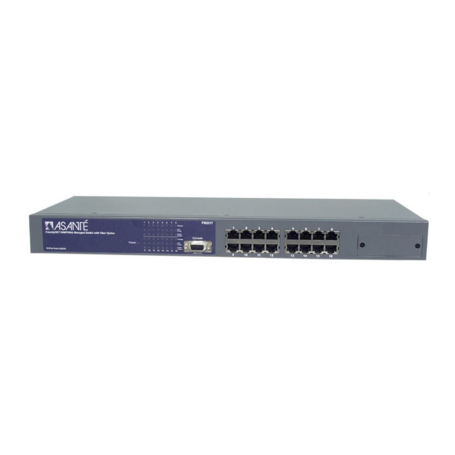
Page 9: Front Panels
• FX100-MMC • FX100-SMC15 • FX100-SMC30 • FX100-SMC60 The FX100 modules are designed to extend the allowable distance between the switch and other network devices. The maximum distance that can be achieved with fiber cabling is 2 kilometers (multi-mode fiber) and up to 15, 30 or 60 kilometers (single-mode fiber). -
Page 11: Chapter 3. Network Application
For example, two Ethernet switches, both with PCs and/or a print server, and a local server can all connected to the FM2017. All of the devices in this configuration can communicate with each other through the FM2017. Connecting a server to the switch allows other users to access that server’s data. -
Page 13: Chapter 4. Network Configuration
Chapter 4. Network Configuration This chapter explains how to configure console management via a direct connection to the console port of the switch. Console management involves the administration of the switch via a direct connection to the RS-232 console port. This port is a female DB-9 connector. From the main menu of the console program, the user has access to manage the functions of the switch. -
Page 14: Assigning Ip Address
---<<Current configuration>>---------------------------[1.0(beta 2)]---- [MAC=00:00:94:D1:1C:22] [IP=192.168.0.1] [mask=255.255.255.0] [broadcast=255.255.255.255] [gateway=0.0.0.0] ------------------------------------------------------------------------ 1. boot-method = [flash] 2. ip-address = [192.168.0.1] 3. subnet mask = [255.255.255.0] 4. broadcast = [255.255.255.255] 5. gateway = [0.0.0.0] 6. traps=[0.0.0.0] [0.0.0.0] [0.0.0.0] [0.0.0.0] 7. get-community = [public] 8. set-community = [private] 9. -
Page 15: Secured Ip
E. Http server = [on] F. Telnet/Http username = [root] G. Telnet/Http password = [enabled] H. reboot I. logout J. ping M. securedip = [0.0.0.0],[0.0.0.0],[0.0.0.0] >>>> Press H to reboot the switch after making your change. Press Enter twice, and the new IP address will now be displayed. -
Page 17: Chapter 5. Web-Based Management
This section introduces the configuration and functions of the web-based management of switch. The FM2017 provides an embedded HTML website residing in the CPU module. It offers management features and allows users to manage the switch from anywhere on the network through a standard web browser. -
Page 18: Statistics Screen
Inside the System page, the following information about the switch is listed: Network Setting • IP address: 192.168.0.1 • Subnet Mask: 255.255.255.0 • Broadcast: 255.255.255.255 • Default gateway: 0.0.0.0 The configuration above is only a reference setting. If you want to reset or change the numbers, you can click Agent Config to change or reset them. - Page 19 The data is automatically updated at regular intervals. Port Config Screen You can use the Port Config page to disable/enable each port. By default, all the ports are Enabled. To disable or enable a port: Select the drop-down menu in the Status column. Choose the status you want for each Ethernet and Fiber port.
-
Page 20: Vlan Screen
To set these parameters for a port: Select the drop-down menu in Speed/Duplex column. Select one of the following choices: Auto/flow control enabled, Auto/flow control disabled, 100Base- Tx/Full Duplex, 100Base-Tx/Half Duplex, 10Base-T/Full Duplex or 10Base-T/Half Duplex. Click Apply. VLAN Screen A VLAN (Virtual LAN) is a group of switch ports designated by the switch as belonging to the same broadcast domain. -
Page 21: Snmp Management
Agent Config Screen In the Agent Config page, the switch’s current configurations are displayed. You can refer to the following Agent Config page for your own setting. Boot Method There are three modes of Boot Method: • FLASH: Boot your system by flash settings. Flash memory resides in a chip and holds its content without power. - Page 22 Default Agent Configuration The following are the default values of the Agent Config of the switch. You can change the information listed by entering new information (for example, you can change the switch’s IP address by directly typing in a new IP address).
-
Page 23: Appendix A. Troubleshooting
Appendix A. Troubleshooting This section is intended to help you solve the most common problems on the switch. If you still are having problems after reading through the information here, contact Asanté’s Technical Support for assistance. Your switch can easily be monitored through the LED indicators to assist in identifying problems. Below are listed common problems that you may encounter and where you can find possible solutions. -
Page 25: Appendix B. Internet Explorer Setting
Appendix B. Internet Explorer Setting If you are using Internet Explorer, you have to modify the browser setting to enable Java applets to use network ports. We used Internet Explorer 5.0 for the following demonstration. First, select ”Internet Optional..” under “Tools” of the function bar, then follow the step-by-step instructions below. - Page 26 Go back to Internet Options, then click Custom Level. Scroll down to find Java. Select Custom under Java and click Java Custom Settings. Select the Edit Permissions tab. 10. Select Enable under Unsigned Content, and then press OK.
-
Page 27: Appendix C. Specifications And Warranty Statement
Appendix C. Specifications and Warranty Statement FriendlyNET FM2017 Specifications Standards Protocol Maximum Forwarding Rate LED Indicators Copper Network Cables Fiber Link Maximum Distance Interface Dimensions Operational Temperature Storage Temperature Operational Humidity External Power Supply Power Consumption Safety Limited Warranty FriendlyNET Limited 2-Year Warranty Subject to the limitations and exclusions below, Asanté... - Page 28 FriendlyNET FM2017 SNMP/Web Managed Switch with Fiber Option User’s Manual Asanté Technologies, Inc. 821 Fox Lane San Jose, CA 95131 SALES 800-662-9686 Home/Office Solutions 800-303-9121 Enterprise Solutions 408-435-8388 TECHNICAL SUPPORT 801-566-8991: Worldwide 801-303-3787: FAX www.asante.com support@asante.com Copyright 2002 Asanté Technologies, Inc. All rights reserved. No part of this document, or any associated artwork, product design, or design concept may be copied or reproduced in whole or in part by any means without the express written consent of Asanté...
Need help?
Do you have a question about the FriendlyNET FM2017 and is the answer not in the manual?
Questions and answers