Table of Contents
Advertisement
Quick Links
Doc number: UM-KT133TX-E2.............................................................................PRINTED IN TAIWAN
V
I
A
V
I
A
V
I
A
K
T
1
3
3
A
A
K
T
1
3
3
A
A
K
T
1
3
3
A
A
F
o
r
A
M
D
F
o
r
A
M
D
F
o
r
A
M
D
A
t
h
l
o
n
A
t
h
l
o
n
A
t
h
l
o
n
S
u
p
p
o
S
u
p
p
o
S
u
p
p
o
K
T
1
3
3
a
n
K
T
1
3
3
a
K
T
1
3
3
a
T
X
C
h
i
p
s
e
T
X
C
h
i
p
s
e
T
X
C
h
i
p
s
e
D
u
r
o
n
T M
a
n
D
u
r
o
n
a
D
u
r
o
n
a
T M
p
r
o
c
e
s
s
p
r
o
c
e
s
s
p
r
o
c
e
s
s
r
t
i
n
g
M
o
d
r
t
i
n
g
M
o
d
r
t
i
n
g
M
o
d
K
T
1
3
3
T
K
T
1
3
3
K
T
1
3
3
K
T
1
3
3
B
K
T
1
3
3
B
K
T
1
3
3
B
K
T
1
3
3
B
K
T
1
3
3
K
T
1
3
3
K
T
3
A
B
K
T
3
A
B
K
T
3
A
B
K
T
3
A
B
K
T
3
A
K
T
3
A
K
T
3
E
B
K
T
3
E
B
K
T
3
E
B
d
n
d
n
d
t
s
t
s
t
s
d
n
d
n
d
o
r
o
r
o
r
e
l
e
l
e
l
X
T
X
T
X
X
X
X
L
B
L
B
L
X
X
X
L
B
L
B
L
X
X
X
Advertisement
Table of Contents

Subscribe to Our Youtube Channel
Related Manuals for AZZA KT133TX


Summary of Contents for AZZA KT133TX
- Page 1 Doc number: UM-KT133TX-E2…………………………………………………………………..PRINTED IN TAIWAN...
- Page 2 ’ ’ ’ This publication contains information that is protected by copyright. No part of it may be reproduced in any form or by any means or used to make any transformation adaptation without prior written permission from the copyright holders. This publication is provided for informational purposes only.
-
Page 3: Table Of Contents
– – Section Sub-section Page Mainboard Layout……………………………………………………. 1.1.1 Mainboard Dimension………………………………………….…… 1.1.2 Environment Limitation……………………………………..……… ATX Form Factor……………………………………………………… Features and Specifications………………………………………. System Health Monitoring Function…………………………… 1.4.1 Hardware Monitoring System Utility…………………………… 1.4.2 Installation of HMSU………………………………………………… Intelligence…………………………………………………………….. Chapter 2 - Hardware Installation Section Sub-section Page Mainboard Setting………………………………………………. - Page 4 – – Section Sub-section Page AWARD BIOC CMOS Setup Utility…………………………. Main Menu…………………………………………………………. Standard CMOS Setup…………………………………………. Advanced BIOS Features……………………………………… Advanced Chipset Features………………………………….. Integrated Peripherals…………………………………………. 4-13 Power Management…………………………………………….. 4-16 PnP/PCI Configuration…………………………………………. 4-20 PC Health Status…………………………………………………. 4-22 3.10 Frequency/Voltage Control………………………………….. 4-23 3.11 Load Optimized Default……………………………………….. 4-24 3.12 Set Supervisor Password………………………………………...
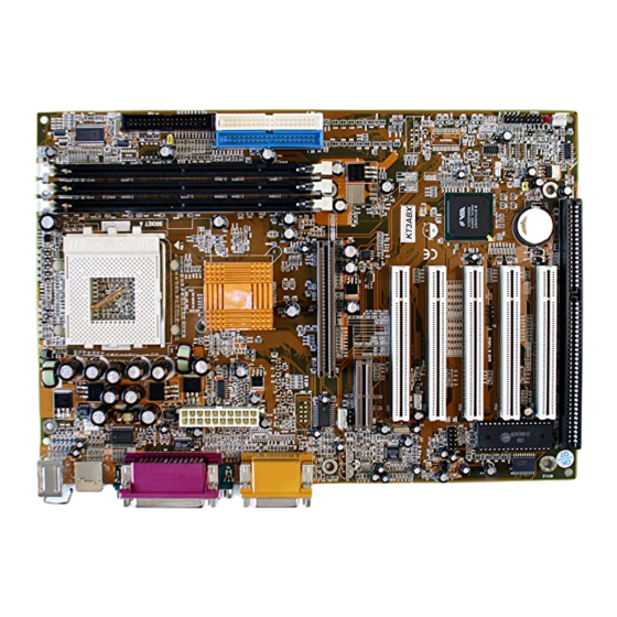
- Page 5 ATX-Power Sleep Panel Chassis Connector Button PWR-LED Note! Audio port (CN18) and AMR slot are only available in KT133TX, KT133BX KT3EBX and KT3ABX models only. Width & Length: 305 mm x 210 mm. Height: 1 1/2 inches PCB Thickness: 4 layers, 0.05 inches.
-
Page 6: Atx Form Factor
COM 2 Audio Port Support AMD Duron TM and Athlon TM Socket A processors. VIA ® VT8363/VT82C686A enhanced AGPset (PC-133) for KT133TX. VIA ® VT8363/VT82C686B enhanced AGPset (PC-133) for KT133BX and KT133BL. VIA® VT8363E/VT82C686B enhanced AGPset (PC-133) for KT3EBX. VIA ® VT8363A/VT82C686B enhanced AGPset (PC-133) for KT3ATX and KT3ABL. - Page 7 Data Path: 8-bit, 16-bit, 32-bit, 64-bit. Address Path: 32-bit. KT133TX, KT133BX, KT133BL and KT3EBX support 200MHz. [100MHz DDR (Double Data Rate)] FSB. KT3ABX and KT3ABL support 200 and 266MHz. [133MHz DDR (Double Data Rate)] FSB. Award BIOS, Windows ® 95/98 Plug and Play compatible.
-
Page 8: Hardware Monitoring System Utility
One game/MIDI port. Three audio jacks: line-out, line-in and mic-in. Two PCI IDE interfaces support up to four IDE devices. Supports ATA/33 and ATA/66 hard drives for KT133TX. Support ATA/33, ATA/66 and ATA100 hard drives for KT133BX, KT133BL, KT3EBX, KT3ABX and KT3ABL. -
Page 9: Intelligence
Note: Use this utility only in Windows ® 95 or Windows ® 98 operating system. To install the utility, please insert the CD Driver into the CD-ROM drive. The auto run screen (Driver Utility) will automatically appear. Click the Hardware Monitoring button, chose the chipset, model number and OS to install. -
Page 10: Chapter 2 - Hardware Installation
Before you start installation, a grounded anti-static mat is recommended. Attached an anti static wristband to your wrist and have it grounded to the same point as the anti-static mat. The following steps must be completed before your can use your PC: - Check and Setup Mainboard Settings. -
Page 11: Installation Of Processor
! According to the documentation from AMD, Duron™ and Athlon™ processors require larger heat sink. The rotation speed of the cooling fan is 6,600 RPM or above. Thermal grease must be applied between the heat sink and the CPU to improve heat dissipation. Also, ensure that the heat sink is fastened securely on the CPU. -
Page 12: Internal Connectors
This mainboard uses only Dual Inline Memory Module. Sockets available 3.3-volt (power level) un-buffered Synchronous Dynamic Random Access (SDRAM) memory system of 16, 32, 64, 128 or 256MB. It’s support single-side double-side SDRAM DIMM module maximum DIMM 1 memory size supported DIMM 2 1536MB. -
Page 13: Amr Slot
Both PCI and PCI expansion cards may require IRQs, this mainboard complies with Plug and Play (PnP) specification that allow automatic system configuration whenever a PnP compliant card is added. For PnP card, IRQs assigned automatically for those available. If older legacy cards that are not support by the BIOS, please contact your vendor for an ISA ISA slots... -
Page 14: Primary And Secondary Ide Connectors
This connector support Floppy drives. Uses the ribbon cable provided and make sure that the red strip is connect to PIN 1 of the connector. CN8: FDC Connector Each IDE connector supports two IDE drives. If you install two hard drives, you need to configure the second drive to Slave mode. -
Page 15: Standard Infrared (Sir) Connector
This IR connector (SIR) supports optional wireless transmitting and receiving infrared module. You must configure the setting through URAT2 to select whether URAT2 is directed for use with COM 2 or IrDra. +5VDC NO CONNECTION IR RECEIVE GROUND IR TRANSMIT CN 12: IR (SIR) CONNECTOR CN17 CN13... -
Page 16: Atx Power Connector
This connector connects to an ATX power supply. The plug from the power supply will only insert in one orientation because of the different hole sizes. Find the right orientation and push down firmly and make sure that the pins are aligned. -
Page 17: Cd Audio-In Connector
L = Left channel audio-out R = Right channel audio-out The CD audio-in connectors on the G = Audio Ground board are used to connect CD ROM audio out. There are two different types of connectors, depending on 1 2 3 4 1 2 3 4 the type of your CD ROM drive CN22... - Page 18 Ground (BLACK WIRE) DATA- (WHITE WIRE) DATA+ (GREEN WIRE) DATA+ (GREEN WIRE) DATA- (WHITE WIRE) Ground (BLACK WIRE) +5V DC (RED WIRE) Ground (BLACK WIRE) RS: Reset Button Connector When connected to the chassis reset button, you can reset your PC when press this button.
- Page 19 Press the Power on button (less than 4 seconds), the system will return to Full-ON mode. Press and hold the Power On Button for more than 4 seconds, the system will be powered off. Mode 2: Press and hold the Power ON button for more than 4 seconds, the system will be completely powered off.
-
Page 20: External Connector
PWRLED: Front Panel Power LED Connector Connect your chassis Power LED connector to this four pins connector. Pin # Signal name Pullup (+ 5V DC for Power LED) ● No Connection ● Ground ● No Connection ● Ribbon cable should always be connected with the red strip to the PIN 1 on the connector of the devices such as CD ROM and Hard Drive. -
Page 21: Ps/2 Mouse And Keyboard Connectors
This connector only supports PS/2 mouse and keyboard plugs. If you have a standard AT size (large DIN) keyboard plug, you need to use a mini DIN adapter. Two serial ports are available for mouse and other serial devices. (I/O addresses used 3F8H/2F8H/3E8H/2E8H... -
Page 22: Award Bioc Cmos Setup Utility
There is the 3D audio interface built on this mainboard (audio interface is optional on the board.). Please refer to the following picture for the audio interface. The EEPROM on the mainboard stores the AWARD BIOS CMOS Setup Utility to allows you to configure your system. -
Page 23: Standard Cmos Setup
CMOS Setup Utility – Copyright ( C ) 1984 - 2000 Award Software. Standard CMOS Setup Frequency / Voltage Control Load Optimized Defaults Advanced BIOS Features Set Supervisor Password Advanced Chipset Features Set User Password Integrated Peripherals Save & Exit Setup Power Management Setup Exit Without Saving PNP/PCI Configuration... - Page 24 CMOS Setup Utility - Copyright ( C ) 1984 - 2000 Award Software. Date (mm : dd : yy) : Tue, 1 2000, Item Help Time (hh : mm : ss) : 16 : 03 : 33 Menu Level IDE Primary Master Maxtor 52049H4 Change this day, month, IDE Primary Slave...
-
Page 25: Advanced Bios Features
Move the selection bar to the appropriate field and press "ENTER" key, the system BIOS will detect the HDD type automatically. Drive A /B: Select the correct specifications for the diskette drive(s) installed in the computer. None No diskette drive installed 360K, 5.25 in 5-1/4 inch PC-type standard drive;... - Page 26 CPU L2 Cache ECC Checking : Enabled Quick Power On Self Test : Enabled Allows you to choose First Boot Device : Floppy the Virus warning Second Boot Device : HDD-0 feature for IDE Hard Third Boot Device : LS120 disk boot sector Boot Other Device : Enabled...
- Page 27 When you select Enabled, memory checking is enabling when the external cache contains ECC SDRAMs. Quick Power On Self Test: Select Enabled to reduce the amount of time required to run the power-on self-test (POST). A quick POST skips certain steps. We recommend that you normally disable quick POST.
- Page 28 If you happen to forget your password, you can clear the password by erasing the CNOS Real Time Clock (RTC) Ram. To erase the RTC Ram Data, please do the following. Clear RTC RAM 1. Unplug your PC. 2. Short the PIN 2 and PIN 3 of Jumper 1 (JP1) 3.
-
Page 29: Advanced Chipset Features
Note! Using this feature may decrease system performance. Video BIOS / XXXX-XXXX Shadow These fields allow you to change the Video BIOS location from ROM to RAM. The system performance is enhancing when you enable this option, as information access is faster through RAM than ROM. - Page 30 conventional ISA bus and the PCI bus. The default settings have been chosen because they provide the best operating conditions for your system. So please do not change the default setting unless you have sound technical background. DRAM Timing By SPD When enabled, the system BIOS will read the DRAM parameters from the SPD (Special Presence Detect) chip on the DIMM module and set the DRAM timing automatically.
- Page 31 System BIOS Cacheable Selecting “Enabled” allows caching of the system BIOS ROM at F0000h-FFFFFh, resulting in better system performance. However, if any program writes to this memory area, a system error may result. Video RAM Cacheable Select Enabled allows caching of the video RAM , resulting in better system performance. However, if any program writes to this memory area, a system error may result.
- Page 32 On-Chip Sound This item allows you to control the onboard AC 97 audio. On-Chip Modem This item allows you to control the onboard MC 97 Modem. CPU to PCI Write buffer When this field is enabled, writes from the CPU to the PCI bus are buffered, to compensate for the speed differences between the CPU and the PCI bus.
-
Page 33: Integrated Peripherals
When Enabled, read to the AGP (Accelerated Graphics Port) are executed with one-wait states. CMOS Setup Utility - Copyright (C) 1984 - 1999 Award Software Integrated Peripherals On-Chip IDE Chanel0 Enabled Item Help On-Chip IDE Chanel1 Enabled IDE Prefetch Mode Enabled Menu Level Ø... - Page 34 IDE Prefetch Mode The onboard IDE drive interfaces supports IDE prefetching for faster drive accesses. If you install a primary and/or secondary add-in IDE interface, set this field to disabled if the interface does not support prefetching. Primary/Secondary, Master/Slave PIO The four IDE PIO (Programmed Input/Output) fields let you set a PIO mode (0-4) for each of the four IDE devices that the onboard IDE interface supports.
-
Page 35: Power Management
IR Function Duplex This item allows you to select the IR half/full duplex function. TX, RX inverting enable This item allows you to enable the TX, RX inverting which depends on different H/W requirement. This field is not recommended to change its default setting for avoiding any error in your system. - Page 36 ACPI Function Disabled Item Help Power Management Press Enter Menu Level Ø ACPI Suspend Type S1 (POS) PM Control By APM Video Off Option Suspend -> off Video Off Method Blank Screen Modem Use IRQ Soft-Off by PWRBTN Instant – off. Wake-Up Events Press Enter The Power Management Setup allows you to configure you system for effectively energy...
- Page 37 HDD Power Down When enabled and after the set time of system inactivity, the hard disk drive will be powered down while all other devices remain active. Doze Mode When enabled and after the set time of system inactivity, the CPU clock will run at slower speed while all other devices still operate at full speed.
- Page 38 MODEM Use IRQ This determines the IRQ in which the MODEM can use for power saving purpose. This mainboard has the ACPI feature designed on the board and it wills “wakeup” automatically when it detects the incoming modem Ring-in signal. Before you can use the Ring-in signal to wakeup your PC system, you have to install the “External”...
-
Page 39: Irqs Activity Monitoring
When you set to LPT & COM mode, any activity from one of the listed system peripheral devices or IRQs wakes up the system. HDD & FDD When you set to HDD & FDD mode, any activity from one of the listed system peripheral devices wakes up the system. -
Page 40: Pnp/Pci Configuration
IRQ9 (IRQ2 Redir) Disabled IRQ10 (Reserved) Disabled IRQ11 (Reserved) Disabled IRQ12 (PS/2 Mouse) Enabled IRQ13 (Coprocessor) Enabled IRQ14 (Hard Disk) Enabled IRQ15 (Reserved) Disabled CMOS Setup Utility - Copyright (C) 1984 - 1999 Award Software PnP/PCI Configuration PnP OS Installed Item Help Reset Configuration Data : Disabled... -
Page 41: Pc Health Status
Legacy ISA Devices compliant with the original PC AT bus specification, requiring a specific interrupt (such as IRQ4 for serial port 1). PCI/ISA PnP Devices compliant with the Plug and Play standard, whether designed for PCI or ISA bus architecture. DMA Resources When resources are controlled manually, assign each system DMA channel as one of the following types, depending on the type of device using the interrupt. -
Page 42: Frequency/Voltage Control
This field will show you the current temperature inside the PC system. Current CPUFAN1 Speed This field will show you the current CPU Cooling FAN1 speed. Current CPUFAN2 Speed This field will show you the current CPU Cooling FAN2 speed. Vcore This field and the files blow show you the current system voltage CMOS Setup Utility - Copyright (C) 1984 - 1999 Award Software... -
Page 43: Load Optimized Default
CMOS Setup Utility - Copyright (C) 1984 - 1999 Award Software Standard CMOS Features Frequency / Voltage Control Advanced BIOS Features Load Optimized Defaults Advanced Chipset Features Set Supervisor Password Integrated Peripherals Set User Password Power Management Setup Save & Exit Setup PNP/PCI Configuration Exit Without Saving PC Health Status... - Page 44 Advanced BIOS Features Load Optimized Defaults Advanced Chipset Features Set Supervisor Password Integrated Peripherals Set User Password Power Management Setup Save & Exit Setup PNP/PCI Configuration Exit Without Saving PC Health Status ESC : Quit ↑↓→← : Select Item F10 : Save & Exit Setup Time, Date, Hard Disk Type ...
- Page 45 PNP/PCI Configuration Exit Without Saving PC Health Status ESC : Quit ↑↓→← : Select Item F10 : Save & Exit Setup Time, Date, Hard Disk Type ... The User Password can be used to check the user's authority. However, this password entry is different from the "SUPERVISOR PASSWORD"...
- Page 46 Integrated Peripherals Set User Password Power Management Setup Save & Exit Setup PNP/PCI Configuration Exit Without Saving PC Health Status ESC : Quit ↑↓→← : Select Item F10 : Save & Exit Setup Time, Date, Hard Disk Type ... Save & Exit Setup: This option will save all setup values to CMOS RAM &...
Need help?
Do you have a question about the KT133TX and is the answer not in the manual?
Questions and answers