Table of Contents
Advertisement
Quick Links
Advertisement
Table of Contents

Related Manuals for VIA Technologies COME8X80


Summary of Contents for VIA Technologies COME8X80
- Page 1 COME8X80 Computer-on-Module Express Revision 1.02 102-03082012-1645...
-
Page 2: Regulatory Compliance
VIA Technologies, Inc. reserves the right the make changes to the products described in this manual at any time without prior notice. -
Page 3: Safety Precautions
Safety Precautions Do’s Always read the safety instructions carefully. Keep this User's Manual for future reference. All cautions and warnings on the equipment should be noted. Keep this equipment away from humidity. Lay this equipment on a reliable flat surface before setting it up. -
Page 4: Box Contents
Box Contents Model Number Description COME8X80 Standard kit 1 x COME8X80 CPU Module 1 x Heat Spreader 1 x Driver CD... -
Page 5: Table Of Contents
Memory Socket: SODIMM1............... 9 COM connectors ....................11 Connector Rows A and B ................11 Connector Rows C and D................14 Mounting the COME8X80 to a Baseboard .........17 3 BIOS Setup......................19 Entering the BIOS Setup Menu ..............20 Control Keys ......................20 Getting Help ......................21 Main Menu ......................22... - Page 6 Date ........................24 Time ........................24 Halt On......................24 HDD Channels ....................25 Advanced BIOS Features................26 Quick Power On Self-Test.................26 First/Second/Third Boot Device............26 Boot Other Device..................26 Boot Up NumLock Status.................27 Typematic Rate Setting ................27 Typematic Rate (Chars/Sec) ..............27 Typematic Delay (Msec)................27 Security Option....................27 Full Screen Logo Show ................27 Summary Screen Show................27 Hard Disk Boot Priority..................28 Advanced Chipset Features.................29...
- Page 7 UR2 Duplex Mode..................35 IR Mode ......................35 RxD, TxD Active .....................35 Onboard Parallel Port.................35 Parallel Port Mode..................35 ECP Mode Use DMA ..................35 VIA OnChip IDE Device .................36 CF Card UDMA66 ..................36 USB Device Setting ...................37 USB 1.0 Controller ..................37 USB 2.0 Controller ..................37 USB Operation Mode ................37 USB Keyboard Function................37 USB Storage Function................38...
-
Page 8: Overview
Overview... -
Page 9: Key Components
The VIA COME8X80 is a compact and highly integrated COM Express Module. It comes with an integrated VIA Nano 1.6 GHz NanoBGA2 processor (or VIA Nano 800 MHz), boasting of ultra- low power consumption, cool and quiet operation. The COME8X80 is based on the VIA VX800 all-in-one single... -
Page 10: Specifications
PECIFICATIONS Processor Processor Core Processor Processor • VIA Nano 1.6 GHz NanoBGA2 Processor • VIA Nano 800 MHz NanoBGA2 Processor (Other CPU frequencies are available for ODM projects) Chipset Chipset Chipset Chipset • VIA VX800 Advanced all-in-one system processor System Memory System Memory System Memory System Memory... - Page 11 Mechanical and COM Express Pin- - - - out Type COM Express Pin out Type COM Express Pin COM Express Pin out Type out Type Environment • Compliant to COM Express type 2 Dimension Dimension Dimension Dimension • 95 mm x 125 mm Operating Temperature Operating Temperature Operating Temperature...
-
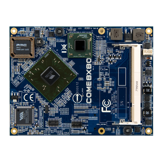
Page 12: Board Layout
OARD AYOUT Top View Bottom View... -
Page 13: Board Dimensions
OARD IMENSIONS... -
Page 14: Hardware Installation
Hardware Installation... -
Page 15: Cpu
The VIA COME8X80 board is designed with the VIA Nano 1.6 GHz NanoBGA2 processor. Other processor options (e.g., VIA Nano 800 MHz NanoBGA2 processor) are also available as manufacturing options. The VIA Nano 1.6 GHz processors requires a heatsink with fan to provide sufficient cooling. -
Page 16: Memory Module Installation
EMORY ODULE NSTALLATION Memory Socket: SODIMM1 The VIA COME8X80 has one 200-pin SODIMM socket for DDR2 533/667 SODIMM SDRAM, non-ECC, memory module and supports memory the sizes up to 2 GB. Available DDR2 SDRAM Configuration Refer to the table below for available DDR2 SDRAM configurations on the mainboard. -
Page 17: Installing The Memory
Installing the memory Step 1 Step 1 Step 1 Step 1 Insert the memory module into the SODIMM socket at a 45 degrees angle. And make sure the notch is on the proper side. Step 2 Step 2 Step 2 Step 2 Then push down until the memory module snaps into place. -
Page 18: Com Connectors
CONNECTORS The COM connectors on the bottom of the COME8X80 provide full IO support from the COME8X80 CPU module to the baseboard. The pinout of the COM connectors is as shown in the table below. Connector Rows A and B... - Page 19 SUS_S5# PWR_OK ATA_ACT# AC_SYNC AC_RST# AC_SDIN0 GND (FIXED) GND (FIXED) AC_BITCLK SPKR AC_SDOUT I2C_CK BIOS_DISABLE# I2C_DAT THRMTRIP# THRM# USB_4_5_OC# USB4- USB5- USB4+ USB5+ GND (FIXED) GND (FIXED) USB2- USB3- USB2+ USB3+ USB_2_3_OC# USB_0_1_OC# USB0- USB1- USB0+ USB1+ VCC_RTC EXCD1_PERST# EXCD0_PERST# SYS_RESET# LPC_SERIRQ CB_RESET#...
- Page 20 LVDS_A2+ LVDS_B2+ LVDS_A2- LVDS_B2- LVDS_VDD_EN LVDS_B3+ LVDS_A3+ LVDS_B3- LVDS_A3- LVDS_BKLT_EN GND (FIXED) GND (FIXED) LVDS_A_CK+ LVDS_B_CK+ LVDS_A_CK- LVDS_B_CK- LVDS_I2C_CK LVDS_BKLT_CTRL LVDS_I2C_DAT VCC_5V_SBY GPI3 VCC_5V_SBY KBD_RST# VCC_5V_SBY KBD_A20GATE VCC_5V_SBY PCIE0_CK_REF+ PCIE0_CK_REF- VGA_RED GND (FIXED) GND (FIXED) VGA_GRN VGA_BLU GPO0 VGA_HSYNC VGA_VSYNC VGA_I2C_CK VGA_I2C_DAT VCC_12V...
-
Page 21: Connector Rows C And D
Connector Rows C and D Pin-out Name Pin-out Name (Row C) (Row D) GND (FIXED) GND (FIXED) IDE_D7 IDE_D5 IDE_D6 IDE_D10 IDE_D3 IDE_D11 IDE_D15 IDE_D12 IDE_D8 IDE_D4 IDE_D9 IDE_D0 IDE_D2 IDE_REQ IDE_D13 IDE_IOW# IDE_D1 IDE_ACK# GND (FIXED) GND (FIXED) IDE_D14 IDE_IRQ IDE_IORDY IDE_A0... - Page 22 PCI_IRQA# PCI_IRQB# PCI_CLK GND (FIXED) GND (FIXED) PEG_RX0+ PEG_TX0+ PEG_RX0- PEG_TX0- PEG_RX1+ PEG_TX1+ PEG_RX1- PEG_TX1- PEG_RX2+ PEG_TX2+ PEG_RX2- PEG_TX2- GND (FIXED) GND (FIXED) PEG_RX3+ PEG_TX3+ PEG_RX3- PEG_TX3- RSVD RSVD RSVD RSVD RSVD GND (FIXED) GND (FIXED) RSVD IDE_CBLID# DVP1_D0 DVP1_D1 DVP1_D2 DVP1_D3 GND (FIXED)
- Page 23 C101 D101 BLT_CK C102 D102 C103 D103 C104 VCC_12V D104 VCC_12V C105 VCC_12V D105 VCC_12V C106 VCC_12V D106 VCC_12V C107 VCC_12V D107 VCC_12V C108 VCC_12V D108 VCC_12V C109 VCC_12V D109 VCC_12V C110 GND (FIXED) D110 GND (FIXED)
-
Page 24: Mounting The Come8X80 To A Baseboard
Step 2 Step 2 Step 2 Align the COM connectors on the bottom side of the COME8X80 to the COM receptacles on the baseboard. Mount the COME8X80 and secure it to the baseboard with the five spacers that have the M2.5*4 bottoms. - Page 25 Step 4 Step 4 Step 4 Step 4 Mount the heat spreader onto the COME8X80 and secure it with five M2.5*8 screws. Note: If a heatsink is required, then the heatsink should be installed onto the COME8X80 before installing the heat spreader. Then...
-
Page 26: Bios Setup
BIOS Setup... -
Page 27: Entering The Bios Setup Menu
BIOS S NTERING THE ETUP Power on the computer and press <Delete Delete> during the beginning Delete Delete of the boot sequence to enter the BIOS setup menu. If you missed the BIOS setup entry point, restart the system and try again. ONTROL Keys Description... -
Page 28: Getting Help
ETTING The BIOS setup program provides a “General Help General Help” screen. You General Help General Help can display this screen from any menu/sub-menu by pressing <F1 F1>. The help screen displays the keys for using and navigating F1 F1 the BIOS setup. -
Page 29: Main Menu
The Main Menu contains thirteen setup functions and two exit choices. Use arrow keys to select the items and press <Enter Enter Enter Enter> to accept or enter Sub-menu. Standard CMOS Features Use this menu to set basic system configurations. Advanced BIOS Features Use this menu to set the advanced features available on your system. -
Page 30: Frequency/Voltage Control
Frequency/Voltage Control Use this menu to set the system frequency and voltage control. Load Optimized Defaults Use this menu option to load BIOS default settings for optimal and high performance system operations. Set Supervisor Password Use this menu option to set the BIOS supervisor password. Set User Password Use this menu option to set the BIOS user password. -
Page 31: Date
CMOS F TANDARD EATURES Date The date format is [Day, Month Date, Year] Time The time format is [Hour : Minute : Second] Halt On Set the system’s response to specific boot errors. Below is a table that details the possible settings. Settings Description All Errors... - Page 32 HDD C HANNELS The specifications of your drive must match with the drive table. The hard disk will not work properly if you enter incorrect information in this category. Select “Auto Auto” whenever possible. If Auto Auto you select “Manual Manual Manual Manual”, make sure the information is from your hard...
-
Page 33: Quick Power On Self-Test
BIOS F DVANCED EATURES Quick Power On Self-Test Shortens the Power On Self-Test (POST) cycle to enable a faster boot up time. Settings Description Disabled Standard Power On Self Test (POST) Enabled Shorten Power On Self Test (POST) cycle and boot up time First/Second/Third Boot Device Sets the boot device sequence as the BIOS attempts to load the disk operating system. -
Page 34: Boot Up Numlock Status
Boot Up NumLock Status Sets the NumLock status when the system is powered on. Settings Description Forces keypad to behave as arrow keys Forces keypad to behave as 10-key Typematic Rate Setting Enables “Typematic Rate” and “Typematic Delay” functions. Settings: [Disabled, Enabled] Typematic Rate (Chars/Sec) This item sets the rate (characters/second) at which the system retrieves a signal from a depressed key. - Page 35 RIORITY This is for setting the priority of the hard disk boot order when the “Hard Disk” option is selected in the “[First/Second/Third] Boot Device” menu item.
-
Page 36: Advanced Chipset Features
DVANCED HIPSET EATURES Caution: The Advanced Chipset Features menu is used for optimizing the chipset functions. Do not change these settings unless you are familiar with the chipset. Init Display First Settings: [PCI Slot, Onboard, AGP, PCIEx] VCP/DVP Select Settings: [VCP, DVP] LCD clock source control Settings: [14 KHz, 7 KHz, 110 Hz, 55 Hz] LCD back light control... -
Page 37: Select Display Device
Select Display Device Settings Description Specifies the VGA port as the display port being used. Specifies the LVDS port as the display port being used. Specifies the DVI port as the display port being used. ® HDMI Specifies the HDMI port as the display port being used. -
Page 38: Vga Share Memory Size
VGA C NTERNAL ONTROL VGA Share Memory Size This setting allows you to select the amount of system memory that is allocated to the integrated graphics processor. Settings: [Disabled, 64M, 128M, 256M] Direct Frame Buffer Settings: [Disabled, Enabled] Output Port Settings: [DI0, DI1] Dithering This feature only has effect when the LVDS port is being used. -
Page 39: Onchip Ide Channel 1
NTEGRATED ERIPHERALS OnChip IDE Channel 1 Settings: [Disabled, Enabled] IDE HDD Block Mode Settings: [Disabled, Enabled] SATA Controller Settings: [Disabled, Enabled] SATA Controller Mode Controls the features of the Serial ATA controller within the chipset. Serial ATA is the latest generation of the ATA interface. Serial ATA hard drives deliver transfer speeds of up to 300MB/sec. -
Page 40: Watchdog Support
WatchDog Support The watchdog timer triggers a system reset or other corrective action if the main program becomes unresponsive. Settings Description Disabled The watchdog feature will be disabled. Enabled The system will reset when the watchdog timer reaches 0. WatchDog Count Value Key in a DEC number. -
Page 41: Onboard Serial Port 1
IO D UPER EVICE Note: These settings are based on the SuperI/O of the COMEDB1 carrier board. If other SuperI/O is designed in the carrier board, the setting will be different. Onboard Serial Port 1 Settings: [Disabled, 3F8/IRQ4, 2F8/IRQ4, 3E8/IRQ4, 2E8/IRQ4, 338/IRQ4, 348/IRQ4, Auto] Onboard Serial Port 2 Settings: [Disabled, 3F8/IRQ4, 2F8/IRQ4, 3E8/IRQ4, 2E8/IRQ4,... -
Page 42: Ur2 Duplex Mode
UR2 Duplex Mode Settings: [Half] IR Mode Settings: [1.6 us, 3/16 bit time] RxD, TxD Active Settings: [Hi,Hi , Hi,Lo , Lo,Hi , Lo,Lo] Onboard Parallel Port This specifies the I/O port address and IRQ of the onboard parallel port. Settings: [Disabled, 378/IRQ7, 278/IRQ5, 3BC/IRQ7] Parallel Port Mode Set the parallel port mode. -
Page 43: Cf Card Udma66
VIA O IDE D EVICE CF Card UDMA66 To support only UDMA66 CF Card Settings: [Disabled, Enabled]... -
Page 44: Usb 1.0 Controller
USB D EVICE ETTING USB 1.0 Controller Enable or disable Universal Host Controller Interface for Universal Serial Bus. Settings: [Disabled, Enabled] USB 2.0 Controller Enable or disable Enhanced Host Controller Interface for Universal Serial Bus. Settings: [Disabled, Enabled] USB Operation Mode Auto decide USB device operation mode. -
Page 45: Usb Storage Function
USB Storage Function Enable or disable legacy support of USB mass storage. Settings: [Disabled, Enabled]... -
Page 46: Acpi Suspend Type
OWER ANAGEMENT ETUP ACPI Suspend Type Settings Description S1(POS) S1/Power On Suspend (POS) is a low power state. In this state, no system context (CPU or chipset) is lost and hardware maintains all system contexts. S3(STR) S3/Suspend To RAM (STR) is a power-down state. In this state, power is supplied only to essential components such as main memory and wakeup-capable devices. -
Page 47: Ac Loss Auto Restart
AC Loss Auto Restart The field defines how the system will respond after an AC power loss during system operation. Settings Description Keeps the system in an off state until the power button is pressed Restarts the system when the power is back Former-Sts Former-Sts... -
Page 48: Ps2Kb Wakeup Key Select
AKEUP VENT ETECT PS2KB Wakeup Select This feature has two settings: Hot Key and Password. To select the Password option, press <Page Up> or <Page Down>. To set the password, enter up to eight digits and press <Enter>. Settings: [Hot Key, Password] PS2KB Wakeup Key Select This feature is only available when “Hot Key”... -
Page 49: Poweron By Pci Card
Wake Up on GPI Settings: [Disabled, Enabled] PowerOn by PCI Card Enables activity detected from any PCI card to power up the system or resume from a suspended state. Such PCI cards include LAN, onboard USB ports, etc. Settings: [By OS, Enabled] RTC Alarm Resume Set a scheduled time and/or date to automatically power on the system. -
Page 50: Pc Health Status
PC H EALTH TATUS The PC Health Status displays the current status of all of the monitored hardware devices/components such as CPU voltages, temperatures and fan speeds. -
Page 51: Dram Frequency
REQUENCY OLTAGE ONTROL DRAM Frequency Settings: [DDR2-400, DDR2-533, DDR-667, SPD]... -
Page 52: Load Optimized Defaults
PTIMIZED EFAULTS This option is for restoring all the default optimized BIOS settings. The default optimized values are set by the mainboard manufacturer to provide a stable system with optimized performance. Entering “Y Y Y Y ” and press <Enter> to load the default optimized BIOS values. -
Page 53: Advanced Bios Features
UPERVISOR ASSWORD This option is for setting a password for entering BIOS Setup. When a password has been set, a password prompt will be displayed whenever BIOS Setup is run. This prevents an unauthorized person from changing any part of your system configuration. - Page 54 & E ETUP Entering “Y Y Y Y ” saves any changes made, and exits the program. Entering “N N N N ” will cancel the exit request.
- Page 55 ITHOUT AVING Entering “Y Y Y Y ’ discards any changes made and exits the program. Entering “N N N N ” will cancel the exit request...
- Page 56 Taiwan Headquarters Europe 1F, 531 Zhong-zheng Road 940 Mission Court In den Dauen 6 Xindian District, New Taipei City 231, Fremont, CA 94539 53117 Bonn Taiwan Germany TEL: 886.2.2218.5452 TEL: 1.510.683.3300 TEL: 49.228.688565.0 FAX: 886.2.2218.5453 FAX: 1.510.687.4654 FAX: 49.228.688565.19 Email: embedded@via.com.tw Email: embedded@viatech.com Email: embedded@via-tech.de China...
Need help?
Do you have a question about the COME8X80 and is the answer not in the manual?
Questions and answers