Table of Contents
Advertisement
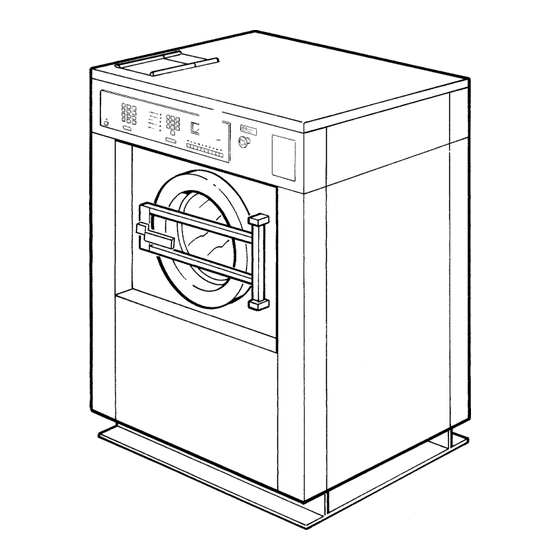
OPERATING & MAINTENANCE MANUAL
From machine No. 91/6411- EX 12, 91/5875- EX 22
WARNING: ALL OPERATING AND MAINTENANCE PROCEDURES SHOWN ON THE NEXT
PAGE OF THIS MANUAL MUST BE FOLLOWED DAILY FOR PROPER OPERATION OF
YOUR WASCOMAT MACHINE.
PLEASE ENTER THE FOLLOWING INFORMATION AS IT APPEARS ON THE MACHINE(S)
DATA PLATE(S).
MACHINE TYPE OR MODEL
MACHINE SERIAL NUMBER(S)
ELECTRICAL CHARACTERISTICS: ________ VOLTS, _______ PHASE, ______ HZ.
MAKE CERTAIN TO KEEP THIS MANUAL IN A SECURE PLACE FOR FUTURE
REFERENCE.
EX-12 HI-TEK
EX-22 HI-TEK
471 1562-62/01
95.38
Advertisement
Table of Contents

Related Manuals for Wascomat EX-12 HI-TEK


Summary of Contents for Wascomat EX-12 HI-TEK
- Page 1 OPERATING & MAINTENANCE MANUAL EX-12 HI-TEK EX-22 HI-TEK From machine No. 91/6411- EX 12, 91/5875- EX 22 471 1562-62/01 95.38 WARNING: ALL OPERATING AND MAINTENANCE PROCEDURES SHOWN ON THE NEXT PAGE OF THIS MANUAL MUST BE FOLLOWED DAILY FOR PROPER OPERATION OF YOUR WASCOMAT MACHINE.
- Page 2 Be sure to keep the machine(s) in proper working order: Follow all maintenance and safety procedures. Further information regarding machine safety, service and parts can be obtained from your dealer or from Wascomat through its Teletech Service Telephone - 516/ 371-0700.
- Page 3 6. To remove top panel for service first remove screws at rear. Be certain to reinstall screws when remounting the top panel. MANUFACTURED BY WASCATOR DISTRIBUTED BY WASCOMAT INWOOD, NEW YORK, USA 471 76 62 02 LOCATED ON THE DOOR:...
-
Page 4: Table Of Contents
Extract-O-Matic EX 12, EX 22 HI-TEK Contents Introduction ................... 1 Technical data ..................2 Installation ..................... 5 Electro-Lube Dispenser ................ 12 Safety rules ................... 15 Mechanical and electrical design ............16 Programming ..................32 Procedure ..................... 54 Maintenance ..................61 Service information ................ -
Page 5: Introduction
When ordering spare parts or contacting Wascomat for any purpose always give the machine serial number, model, voltage and other electrical characteristics appearing on the nameplate at the rear of the machine. -
Page 6: Technical Data
Technical data EX-12 HI-TEK Dry load capacity up to 13,5 kg 30 lbs Overall dimensions Width 870 mm 34 1/4'’ Depth 900 mm 35 15/16'’ Height 1302 mm 51 1/4'’ Net weight 290 kg 639 lbs Dyn.weight 120 lbs./sqft Crated dimensions Volume 1.25 m... - Page 7 Technical data EX 22 HI-TEK Dry load capacity up to 22.5 kg 50 lbs Overall dimensions Width 1000 mm 39 3/8'’ Depth 1102 mm 43 3/8'’ Height 1412 mm 55 9/16'’ Net weight 553 kg 1218 lbs Dyn.weight 157 lbs./sqft Crated Dimensions Volume 2.05 m...
- Page 8 Technical data Outline and dimensions 5 4 3 1 Opening for electrical cable connection 2664 2 Steam connection (optional) 3 Cold water 4 Hot water 5 Hot water (only EX22) 6 Drain outlet 7 Soap box EX12 EX 22 inches inches 34 1/4 1000...
-
Page 9: Installation
Installation Installation The machine is delivered with expansion bolts and other items packed inside the drum. Shipping securities The machine is shipped with four large metal Fig. bracket bolted to the suspension legs, as well as a support between the pulley and the back plate. Prior to installation, follow these steps: •... - Page 10 Installation Mechanical installation EX12 • Mark and drill two holes 3/8'' in (8 mm) in Fig. diameter and approximately 3 1/2'' in. (90 mm) 866 mm deep according to the dimensions in figure 5. 34 3/32 in. • Place the machine in position. Never lift the machine by the door or handle.
- Page 11 Installation Electrical installation Although the machines are fitted with thermal Fig. overloads in the motor windings and separate fuses for the control circuit, a separate three- phase circuit breaker must be installed for all three-phase machines. For proper overcurrent protection, check the data plate at the rear of the machine.
- Page 12 Installation Water connection NOTE All plumbing must conform to national and local plumbing codes. Incoming water lines do not require non-return Fig. valves, as the machine is already fitted with a siphon breaker. However, all incoming lines must be fitted with shut-off valves and strainers. Fig.
- Page 13 Installation Connection of external liquid supply Remove cover and cover support over the soap box. Fig. Bend all the way back the metal plate in compartment 3. Pull the knobs up and forward. Fig. 1. Loosen both knobs so that one side of the metal fingers underneath can slide under the Fig.
- Page 14 Installation Fig. 1. Drop the knob into the larger opening in the supply injector lid. 2. Tighten securely. Do not overtighten! Do not use pliers or other tools to tighten the knobs! 1. Stretch the multi-rubber ring B and select the Fig.
-
Page 15: Electrical Connection
Installation Electrical connection At the rear side of the control unit are two quick Fig. connectors. When the machine is delivered connector A is connected. When using powder supply, change to connector B. Pump connection Fig. To the right of the incoming power terminal connection block is the connection for pumps. -
Page 16: Electro-Lube Dispenser
When the oil reaches a low level, the cannister must be replaced with a new one available from Wascomat as Part No. 827601. Date Last Replaced Date Last Replaced... - Page 17 Installation Start-up and safety checklist Before initial start-up of a Wascomat washer- extractor, the following safety checks must be performed: • Make sure that all electrical and plumbing Fig. connections have been made in accordance with applicable local codes. • Use only flexible water fill and drain hoses of the proper length to avoid sags and kinks.
- Page 18 The warranty card should be completed and sent to Wascomat. All other items should be placed in a safe place for future reference. The machine should be cleaned when the...
-
Page 19: Safety Rules
Safety Rules Safety rules • This machine is designed for water washing only. • Machines must not be used by children. • All installation operations are to be carried out by qualified personnel. Licensed personnel are necessary for all electric power wiring. •... -
Page 20: Mechanical And Electrical Design
Mechanical and electrical design General This machine is a free-swinging model i.e. the outer drum and motor bridge are Fig. suspended in the machine chassis via a spring suspension with a strong spring in each corner of the machine. Each spring has a shock absorber which dampens the movement of the machine. - Page 21 Mechanical and electrical design Frame Description The frame is constructed on the free-swinging principle, i.e. the washing Fig. drum is freely and resiliently suspended in the fixed frame. The entire frame is constructed of U-shaped iron beams forming a stable and torsionally rigid structure.
- Page 22 Mechanical and electrical design Drum with bearings Description The inner drum is journalled to the outer drum by two robust bearings in a Fig. bearing housing which is bolted to the rear plate. The bearing unit supports the drum without any support being needed at the front. Shaft seals of the V-type, as well as O-rings, seal against leakage.
- Page 23 Mechanical and electrical design Safety locking device Description The machine safety locking device includes a Fig. safety interlock system which prevents personal injury through the following precautions: • The machine cannot be started until the door is shut. • The door is automatically locked when the machine starts.
- Page 24 Mechanical and electrical design Function If the machine has not been energised within the last three minutes, the door will remain unlocked. When the machine is energised the door will be locked if a program is activated or if the drum is rotating. Upon completion of a program the door will be unlocked automatically as soon as the drum has stopped rotating.
- Page 25 Mechanical and electrical design Fault location Door does not unlock Conditions: wash program ended and drum at a standstill. Measure the voltage between the following points: 1. X93:2 - X93:3 Should be 0 V DC. If the voltage is 220 V AC, check the rotation guard. 2.
- Page 26 Mechanical and electrical design Rotation guard Description The rotation guard checks that the machine is completely at a standstill before the door can Fig. be opened. When the drum has been at a standstill for approx. two seconds the solenoid in the door lock is deactivated and the lock can be opened (provided that the machine has been emptied of water and the programmer has reset).
-
Page 27: Control Unit
Mechanical and electrical design Control unit The control panel (1), mounted at the front, Fig. includes all components necessary for operating the machine, such as display window, control switches and a key-operated switch. The printed circuit board (2) with the microprocessed electronic timer is mounted just behind the control panel. - Page 28 Mechanical and electrical design Relays The HI-Tek models employ six relays. The relays control: • the reversing wash action of the wash motor Fig. (2 relays) • the distribution action of the wash motor • the extraction motor (3 relays) Construction The body of the relay holding the stationary contacts is made of current-resistant plastic.
- Page 29 Mechanical and electrical design Drive motors Description Both motors, one for wash and distribution and Fig. one for extraction, are installed on the same motor bridge. The motors drive the drum and are mechanically connected to each other by V-belts. On the EX 22 there is also an electromechanical clutch.
- Page 30 Mechanical and electrical design Repair instructions Overheated motor, motor not running • Wait till motor has cooled down. Motor thermal protection is automatically reset after approx. 30 minutes. Restart. • Possible cause of motor protector releasing repeatedly: could be oversensitivity of thermal protector.
- Page 31 Mechanical and electrical design Supply injection valve Construction This valve has a single-inlet with three outlets, Fig. each with its own solenoid coil. The body is made of heat-resistant polyamid plastic and the solenoids encased in water-tight plastic. The electrical connector terminals are spade lugs.
- Page 32 Mechanical and electrical design Repair instructions Limescale can block the hole in the valve diaphragm and interfere with the function of the valve. It is therefore advisable to dismantle and clean Fig. the valve at certain regular intervals. The frequency depends on operating conditions and the level of contamination in the water.
- Page 33 Mechanical and electrical design Inlet valve EX 22 Fig. The water inlets have brass bodies with a larger cross section of the outlet in order to acheive a shorter filling time for the machine. Construction The valve housing is made of pressed brass. The spring-loaded plunger is made of stainless steel and located at its lower end is a rubber gasket for the pilot valve.
- Page 34 Mechanical and electrical design Soap supply box The three-compartment soap supply box is located at the top of the machine. Viewed Fig. from the front, the compartments are marked with figures 1, 2 and 3. Compartment 1 and 2 are used for adding detergent directly to the wash. Compartment 3 is used for adding fabric softener.
-
Page 35: Drain Valve
Mechanical and electrical design Drain valve Description The drain valve consists of a bracket (1), on Fig. which are mounted the motor and gear (2) and diaphragm (3). The rubber diaphragm is resistant to a water temperature up to 100°C (212•F). The installation of a lint trap is not necessary. -
Page 36: Programming
Programming General The washing machine’s program operation is controlled by a microcomputer Fig. and the wash programs are stored in an electronic memory. Program controls are very exact and the wash programs can be easily adapted to the end user’s individual requirements. - Page 37 Programming Programming - general description Programming can be divided into two programming principles: Programming a new program or using an old program as a Turn the key to background. ''PROGRAM'' Programming a completely new program The wash program is constructed by selecting Fig.
- Page 38 Programming Using and old program as a background In this operation, an old program is selected as a Fig. background for the new one. The answers to the questions and the written texts can be changed to create a new program. Furthermore, sub- Turn the key to programs can be erased and new sub-programs ''PROGRAM''...
- Page 39 Programming Controls The key switch Turn the switch to the PROGRAM position if the Fig. wash program is to be programmed or changed. If for any reason you wish to discontinue programming and start again, turn the switch to the RUN position and then back to PROGRAM again.
- Page 40 Programming Erase This button can be used in three different ways: Fig. PROGR. MODE SELECT SEQUENCE PREWASH • Deleting a complete program. Press ERASE when the display window displays the adjacent text. Press: A warning text will then be displayed. Press ENTER, enter the program number with the Number ERASE...
- Page 41 Programming YES, NO, number keys Fig. These keys are used to answer the different questions which are found under each sub- program. All answers must be followed by DETERGENT 1 MAIN RINSE pressing ENTER for the answer to be registered. WASH WASH DETERGENT 2...
- Page 42 Programming Programming a new program If you make a mistake or get stuck, there is always a final resort: Turn the key to the RUN position and then to PROGRAM again. Any programming you have carried out so far will be lost but other PROGRAM programs will not be affected.
- Page 43 Programming Answering questions The general principle for answering questions is PROGR.MODE SELECT SEQUENCE PREWASH the same for all sub-programs: PAUS WITH BUZZER Y/N NORMAL ACTION DURING FILLING Y/N • The cursor (the flashing square) is always to GENTLE ACTION DURING FILLING Y/N the right of line three in the display window.
- Page 44 Programming The following is a summary of the different questions that can appear under the different buttons. PROGR.MODE SELECT SEQUENCE PREWASH PAUS WITH BUZZER Y/N NORMAL ACTION DURING FILLING Y/N NOTE: The question which are described do no Press: apply to all machines. On certain types of machines, some of the values are RED.
- Page 45 Programming Refilling LEVEL RESET is value which regulates at which Fig. PROGR. MODE SELECT SEQUENCE PREWASH level water is to be refilled if the water level sinks LEVEL 000 UNITS while a wash is in progress. LEVEL RESET 000 UNITS 000 °C TEMPERATURE Example:...
- Page 46 Programming Water filling One or several water valves can be selected. FIg. PROGR.MODE SELECT SEQUENCE PREWASH If you decide to use hot and cold water, both WASHTIME 00 MIN. 00 SEC. COLD WATER Y/N valves will be open while filling is in progress. The HOT WATER Y/N hot water valve will be automatically closed if the pre-set temperature is exceeded.
- Page 47 Programming Drain Pause with signal PROGR.MODE SELECT SEQUENCE DRAIN Fig. If the question is answered with YES, the washing PAUSE WITH BUZZER Y/N NORMAL ACTION Y/N machine will stop before the sub-program starts and a buzzer will sound. Press: Normal action/gentle action/distribution RED.
- Page 48 Programming Programming complete • When ’’END OF SEQUENCE’’ appears on the PROGR.MODE SELECT SEQUENCE EXTRACT third line of the display window and all questions are answered, press EDIT DOWN. TIME HIGH SPEED 00 MIN. 00 SEC. TIME LOW SPEED 00 MIN. 00 SEC.
-
Page 49: Gentle Action
Programming Special cooling valve Answer YES is there is a separate water valve use FIg. PROGR.MODE SELECT SEQUENCE COOL DOWN for cooling. If the answer is NO, the standard cold PAUSE WITH BUZZER Y/N SEPARATE COOL DOWN VALVE Y/N water inlet is used. GENTLE ACTION Y/N Gentle action Press:... - Page 50 Programming Example: • ON TIME 212-158°F (100-70°C) 8 seconds. • ON TIME 158°F (70°C) - END 13 seconds. • END TEMP. 113°F (45°C). • Wash temperature 194°F (90°C). The following takes place: • When the water in the drum reaches 194-158°F Fig.
- Page 51 Programming Text Each program can be provided with two types of informative text: • 1. A program name which is always displayed Fig. SELECT PROGRAM TOW DIGITS when the program is selected when washing. PROGRAM 01 HEAVY SOIL This text is programmed when the program START WASH WITH START-BUTTON FOR PROGRAM INFO.
- Page 52 Programming Times for normal action and gentle action The times for rotating and stationary drum during Fig. PROGR.MODE MAINDATA normal and gentle action can be programmed. All BUZZER ON WHEN PROGRAM FINISHED Y/N times can be selected within the range of 0-30 GENTLE ACTION ON TIME 00 SEC.
- Page 53 Programming Program names Fig. You can now give the program a name which will be displayed when the program is selected during -ABCDEFGHIJKLMNOPQRSTUVWXYZ !&/()=?;:,.* PROGRAM 10 - washing. The text can be up to 29 characters long. The way in which text is entered described under the heading ’’TEXT’’...
- Page 54 Programming Starting from a previously saved program If you make a mistake or get stuck, there is always a final resort: Turn the key to the RUN position and then to PROGRAM PROGRAM again. Any programming you may have carried out so far will be lost but other programs will not be affected.
- Page 55 Programming The cursor will appear on the first line of this sub- Fig. program. Fig. Use EDIT UP and EDIT DOWN to move within the PROGR.MODE SELECT SEQUENCE MAINWASH sub-program to reach the line(s) to be altered. PAUSE WITH BUZZER Y/N NORMAL ACTION DURING FILLING Y/N NOTE Press:...
-
Page 56: Making Changes To The Program
Programming NOTE PROGR. MODE SELECT SEQUENCE PREWASH Use only EDIT UP and EDIT DOWN for PAUS WITH BUZZER Y/N NORMAL ACTION DURING FILLING Y/N looking through the program. ENTER shall GENTLE ACTION DURING FILLING Y/N only be used for making changes in the program. - Page 57 Programming Altering text The text that is displayed when a program is PROGR.MODE SELECT SEQUENCE selected and PROG.INFO is pressed can be altered. Go to the position between two sub-programs (see Fig. the section ’’Looking through the program’’). Press Press: TEXT and ENTER.
-
Page 58: Procedure
Procedure Procedure for use All operations, including the programming of new wash programs are carried out from the control panel on the front of the machine. During normal use, the programming keys to the left of the panel are inoperative. Fig. - Page 59 Procedure Preparation • Sort the wash according to the washing instructions on the garment labels. Check that there are no foreign objects in the garments. Pull up zipper fasteners. • Open the washing machine door, check that the drum is empty, insert the wash goods and close the door.
- Page 60 Procedure Program information When a program has been selected and PROG. Fig. INFO. is pressed, further information about the program is shown in the display window's bottom lines. Measuring the detergent Five lights on the panel indicate which detergent Fig. compartments will be used, or supply signals PROG.
- Page 61 Procedure Starting the program Fig. Press START/HOLD/RAPID ADV. button. The wash cycle will commence and the display Fig. window will display wash information as shown in the figure below. Temporary stop • Press START/HOLD/RAPID ADV.. All active Fig. functions (motor, filling with water and heating) START COLD HEAT...
- Page 62 Procedure Programmed stop If there is a programmed stop in the program, the Fig. machine stops and a buzzer sounds. The buzzer is switched off by pressing START/ HOLD/RAPID ADV. The program is restarted by pressing the button again. Tumble drying after the program is completed If DOOR LOCK and MOTOR are pressed before Fig.
- Page 63 Procedure Manual washing • The lamps above the control buttons indicate that the function is active. COLD WATER, HOT WATER and FLUSH must be kept pressed to remain active. Other control buttons change function each time they are DRAIN PROG. DOOR °C/°F MOTOR...
- Page 64 Procedure Extract cycle For safety reasons, there is no manual button for the extract cycle. There are two choices if extracting is required during manual operation: • 1. Select one of the standard programs and DRAIN PROG. DOOR °C/°F fast forward to the "Extract" cycle. MOTOR FLUSH CLOSED...
-
Page 65: Maintenance
Maintenance Maintenance Preventive maintenance has been reduced to a minimum by the careful design of reliable components and material. However, the following, measures should be taken at regular intervals and in proportion to the hours of service. IMPORTANT! Make certain that all electrical power to the machine is shut off before removing top or rear panels. -
Page 66: Service Information
Service information Service information Fig. The machine's electrical power connection cable shall be provided with a safety ground to avoid breakdowns in the machine's electronic program controls. If interference problems do occur, check first that the machine is properly grounded. The machine's operation in terms of safety and function is continuously monitored by the program unit. -
Page 67: Trouble-Shooting
Trouble-shooting Trouble-shooting If machine does not start A Check circuit breaker in the power feed line to Fig. the machine. B Check door safety switches. C Check glass cartridge fuses. D Check for fault indication on display (see under the heading ''Service information''). If water does not drain A Check for fault indication on display (see under Fig. - Page 68 Trouble-shooting If machine does not extract A Check for fault indication on display (see under Fig. the heading "Service Information"). B Check extract relays and relay coils for proper operation. If motor does not operate at wash speed A Check for fault indication on display (see under Fig.
- Page 69 Trouble-shooting If machine runs slowly on wash speed or there is a slapping or thumping noise Fig. A Replace V-belts If a metallic noise can be heard at rear of machine Fig. A Tighten lock screw on pulley on motor shaft. If the door is leaking Fig.
- Page 70 Trouble-shooting If there is leaking around the glass Fig. A Re-cement glass in door gasket, if worn. Replace door gasket if worn. If water does not enter the machine A Check for fault indication on display (see under Fig. the heading "Service Information"). B Check the value coils on inlet valves.
- Page 71 Trouble-shooting If water continues to fill without stopping A Check for incorrect programming. Fig. B Check hose attached to level control unit on the printed circuit board. C Check inlet valves for dirt underneath the valve diaphragm. To localize, shut off power. If water continues to flow, inlet valves have foreign material in them and should be thoroughly cleaned.
- Page 72 Trouble-shooting If machine vibrates excessively A Check the out-of-balance detector switch. Fig. B Check the shock absorbers and the springs of the drum suspension. If safety fuse blows at the beginning of the cycle A Replace fuse. Fig. B Disconnect wires leading to the delay circuit of the door lock.
Need help?
Do you have a question about the EX-12 HI-TEK and is the answer not in the manual?
Questions and answers