Table of Contents
Advertisement
Quick Links
Advertisement
Table of Contents

Summary of Contents for Redarc LFP2420-LV
- Page 1 In-vehicle 24V LiFePO Battery Charger LFP2420 / LFP2420-LV...
-
Page 2: Warnings And Safety Instructions
Ensure that the battery’s management system is capable of allowing the battery to be charged with 20A. Please contact REDARC if you are unsure if your battery is compatible. The LFP2420(-LV) will achieve best results when proper battery maintenance is regularly performed. -
Page 3: Table Of Contents
CONTENTS Table of Contents Page Warnings and Safety Instructions Contents Specifications 1 Product Function Display Panel Charging Algorithm Turn On/Off Thresholds Error Codes 2 Installation RED wire - Input Source Positive BLUE wire - Source Select ORANGE wire - Not Used BROWN wire - Auxiliary Battery Positive BLACK wire - Common Ground GREEN wire - Optional External LED Indication... -
Page 4: Product Function
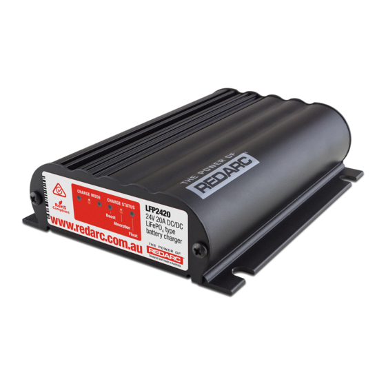
PRODUCT FUNCTION The LFP2420(-LV) is a three stage, 24V DC-DC battery charger that operates from an alternator input of 12V nominal or from a 12V nominal solar panel input. The LFP2420 will also charge from an alternator input of a 24V nominal vehicle. The input voltage of the LFP2420(-LV) can be above, below or equal to the output voltage making it ideal for charging an auxiliary 24V battery where the distance from the main battery may cause a significant voltage drop. -
Page 5: Charging Algorithm
This counteracts the battery’s self discharging or loads applied to the battery. When the battery loses charge, the Charger will move back into the Boost stage. Turn On/Off Thresholds Solar 24V* LFP2420 LFP2420-LV All Models LFP2420 Input Turn ON above 13.2V 12.0V 17.5V... -
Page 6: Error Codes
PRODUCT FUNCTION Error Codes In the event of a fault with the unit installation, either battery or solar panel, ALL the LEDs on the unit will flash to indicate the fault type. Flashing sequences are described in the table below. LED State Description 1 flash (1 flash followed by 3.5 second off) -
Page 7: Blue Wire - Source Select
Red Wire permanently connected to the Input Source Positive supply and the charger will only charge when the alternator is running. This is not suitable for the LFP2420-LV. Input Source Positive 2.1.2 Solar Input The LFP2420 is also capable of charging the auxiliary Connected battery from a Solar source. -
Page 8: Orange Wire - Not Used
INSTALLATION ORANGE wire - Not Used Connected The ORANGE wire is not used on the LFP series chargers. It should be left disconnected. Orange Wire BROWN wire - Auxiliary Battery Positive Brown Wire The BROWN wire should be connected to the auxiliary battery’s positive terminal. -
Page 9: Cable Sizing
We recommend that this activity be undertaken by an appropriately trained person. REDARC recommends using a soldered butt splice crimp connection that is covered with heatshrink. See Figure 2.1. REDARC does not recommend using standard red/ blue/yellow blade connections as they are not rated for either the current required or gauge of wire supplied on the unit. - Page 10 Fuse Fuse* to vehicle ignition Fuse Not Used Auxiliary Start All ground points must Battery Battery be connected to chassis earth. *Fuse Ratings as per table on Page 2 Figure 2.8b - LFP2420-LV Standard setup for a 12V Start Battery...
- Page 11 INSTALLATION Optional LED SOLAR INPUT Green Low Voltage Disconnect 12V Solar Panel Array Load Loads Fuse Fuse Not Used Auxiliary All ground points must Battery be connected to chassis earth. *Fuse Ratings as per table on Page 2 Figure 2.8c - LFP2420 Standard setup for Solar Input...
-
Page 12: Rk1260 Relay Kit
The below diagram shows a changeover relay being controlled by vehicle ignition to automatically swap between alternator and solar panel inputs. A Relay suitable for 12V Vehicle installations is available as part of the REDARC RK1260 Relay Kit. The kit also includes butt-splice connectors, a wiring loom, heat shrink, and instructions. -
Page 13: Troubleshooting
LFP, and the orientation of the LED as per the install diagrams. If the problem is still evident contact a qualified Are all Auto Electrician, or REDARC battery negative wires, Electronics. solar negative wire and BLACK LFP wire connected to a... -
Page 14: Frequently Asked Questions
The unit is also microprocessor controlled allowing it to output a REDARC proprietary charging algorithm independent of the input. This allows the unit to charge specific to the battery type even if the input voltage is low due to voltage drop. -
Page 15: Two Year Warranty
Australian Consumer Law. Redarc Electronics Pty Ltd atf the Redarc Trust trading as Redarc Electronics (“Redarc”) offers a warranty in respect of its Products where the Products are purchased from an authorised distributor or reseller of Redarc by a person (“Purchaser”), on the terms and conditions, and for the duration, outlined below in this document (“Warranty”). - Page 16 Free technical assistance! please contact REDARC Electronics 23 Brodie Road North, Lonsdale SA (08) 8322 4848 power@redarc.com.au www.redarc.com.au Copyright © 2018 REDARC Electronics Pty Ltd. All rights reserved. www.redarc.com.au WARLFP2420-REV3...


Need help?
Do you have a question about the LFP2420-LV and is the answer not in the manual?
Questions and answers