Table of Contents
Advertisement
Available languages
Available languages
Quick Links
Advertisement
Table of Contents

Related Manuals for Monte Carlo Fan Company 4vG42XXd-L series


Summary of Contents for Monte Carlo Fan Company 4vG42XXd-L series
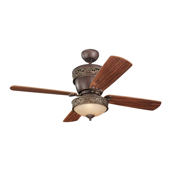
- Page 1 UL Model No. 4VG42/28 Owner’s Manual Ceiling Fan Installation Instructions Downrod without light kit Downrod with light kit Flush Mount -No light kit Flush Mount -Light kit For 4vG42/28XXd-L Series Fan Read and Save TheSe InSTRucTIonS Total fan weight with lights 082509...
-
Page 2: Installation
Installation aFeTy WARNING: TO REDUCE THE RISK OF FIRE, ELECTRIC SHOCK, OR INJURY TO PERSONS, OBSERVE THE FOLLOWING: READ AND SAVE THESE INSTRUCTIONS Installation work and electrical wiring must be done by qualified person(s) in accordance with applicable codes and standards (ANSI/NFPA 70- 1999), including fire-rated construction. - Page 3 house Blue Black Black White White Green Ground Connect black and blue wire from fan Securely attached the mounting plate to Black or (Hot) wire from house. Carefully lift the fan motor assembly to the outlet box using two screws Connect White wire from Fan to and engage the slot in the motor supplied by the outlet box.
- Page 4 For fan with light kit go to step20. For fan without light kit go to Remove the double sided sticky tape Remove the finial, finial cap, hex step 25. and stick the capacitor to the switch nut, and rubber washer from the fit- cap plate.
- Page 5 Use metal outlet box suitable for fan support and use only the screws provided with the outlet box (must support 35 lbs). Before attaching fan to outlet box, ensure the outlet box is securely fas- tened by at least two points to a structural ceiling member ( a loose box will cause the fan to wobble).
- Page 6 Clip Clip in posi- tion Place the motor housing on the polyfoam Hold the motor housing and turn mount- as shown, then locate the mounting plate ing plate clockwise by screwdriver to hold Thread the lead wires through the it with housing in position. Make sure that to the housing by aligning the clips on the the clips are engaged with the mounting motor housing cover...
- Page 7 Go to step 14 to finish installation. Make wire connections to the power source using wire nuts provided. Make sure that no filiments are outside of the wirenut. After making the wire connections, the wires should be spread apart with the grounded con- ductor and the equipment-grounding conductor on one Lift canopy allowing the 2 studs side of the outlet box and ungrounded conductor on...
-
Page 8: Troubleshooting
Trouble Shooting If you have difficulty operating your new ceiling fan, it may be the result of incorrect assembly, installation, or wiring. In some cases, these installation errors may be mistaken for defects. If you experience any faults, please check this Trouble Shooting Chart. If a problem cannot be remedied, or you are experiencing difficulty in installation, please call our Customer Service Center at the number printed on your parts list insert sheet. - Page 9 UL Model No. 4VG42/28 manuel de l´utilisateur Instructions pour l´installation d´un ventilateur de plafond Tige sans kit léger Tige avec le kit léger Bâti affleurant - aucun kit léger Bâti affleurant - kit léger Por 4VG42/28XXD-L Ventilateurs LIRE ET GARDER CES INSTRUCTIONS Poids total du ventilateur...
-
Page 10: Outils Requis
Installation Conseils de sécurité ATTENTION : SUIVRE CES CONSEILS AFIN DE RÉDUIRE LES RISQUES D’INCENDIE, D’ÉLECTROCUTION OU DE BLESSURE. 1. L’installation et le câblage électrique doivent être exécutés par une ou plusieurs personnes qualifiées, conformément à tous les codes et normes (ANSI/NFPA 70-1999) applicables, y compris la construction anti-incendie. - Page 11 Ventilateur Masse Bleu Noir Noir Blanc Blanc Tirez les fils de masse blancs et Vert bâtiment noirs hors de la boîte de sortie par le trou dans le plat de support et éten- dez-les au côté. Attachez solidement Connectez les fils noir et bleu provenant du ventilateur au Soulevez soigneusement le moteur de fils noir ou (chargé) provenant du bâtiment.
- Page 12 Pour le ventila teur avec le kit l éger vont à étape 20. Pour le ventila teur en dehors l Enlevez le double a dégrossi bande e kit léger vont Enlevez le finial, le chapeau de finial, collante et colle le condensateur au l'écrou de sortilège, et la rondelle en plat de chapeau de commutateur.
- Page 13 Utilisez la boîte de sortie en métal appropriée pour l'appui de ventilateur et utilisez seulement les vis équipées de boîte de sortie (doit soutenir 35 livres). Avant d'attacher le ventilateur dans la boîte de sor- tie, assurez que la boîte de sortie est solidement attachée par au moins deux points à...
- Page 14 Pince Pince en place Placer le boîtier du moteur sur le poly- Soutenir le boîtier du moteur et tourner le montant dans le sens des styrène comme illustré, puis installer le Passer les fils dans le couvercle du aiguilles d’une montre à l’aide d’un montant au boîtier en alignant les pinces tournevis afin de le maintenir avec le boîtier du moteur.
- Page 15 Passez à l'étape 14 pour finir l'installa- tion. Établissez les rapports de fil à la source d'én- ergie utilisant des écrous de fil fournis. Assurez-vous qu'aucun filiments n'est en dehors de du wirenut. Après avoir établi les rapports de fil, les fils devraient être répan- dus à...
-
Page 16: Guide De Dépannage
GUIDE DE DÉPANNAGE Si vous éprouvez des difficultés à faire fonctionner votre nouveau venilateur, il se peut que celui-ci ait été mal monté, installé ou branché. Dans certains cas, de telles erreurs d´installation peuvent être prises pour des défectuisités. En cas de problémes, veuillez consulter ce Guide de dépannage. - Page 17 Aug.3.09 Installation way revision. Aug.25.09 Revised step 28. Use plastic plug.
Need help?
Do you have a question about the 4vG42XXd-L series and is the answer not in the manual?
Questions and answers