Advertisement
Quick Links
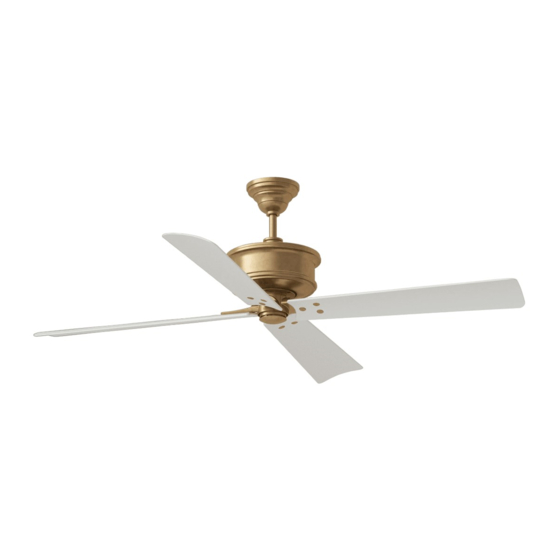
Owner's Guide and Installation Manual
Attach sales receipt to this card and retain as your proof of purchase
DATE OF PURCHASE:
MODEL NUMBER:
To register your fixture, please visit our website www.montecarlofans.com
4SBWR56XXX Series Fan
cETL Model NO. : 4SBWR56XX
RETAILER NAME:
RETAILER ADDRESS:
7.9 kg
17.38 lbs
Total fan weight
Advertisement

Related Manuals for Monte Carlo Fan Company 4SBWR56 Series


Summary of Contents for Monte Carlo Fan Company 4SBWR56 Series
- Page 1 Owner’s Guide and Installation Manual 4SBWR56XXX Series Fan cETL Model NO. : 4SBWR56XX Attach sales receipt to this card and retain as your proof of purchase DATE OF PURCHASE: RETAILER NAME: RETAILER ADDRESS: MODEL NUMBER: To register your fixture, please visit our website www.montecarlofans.com 7.9 kg 17.38 lbs Total fan weight...
-
Page 2: Cautions And Warnings
Cautions and Warnings WARNING: TO REDUCE THE RISK OF FIRE, ELECTRIC SHOCK, OR INJURY TO PERSONS, OBSERVE THE FOLLOWING READ AND SAVE THESE INSTRUCTIONS Installation work and electrical wiring must be done by qualified person(s) in accordance with applicable codes and standards (ANSI/NFPA 70), including fire-rated construction. - Page 3 Before you begin installing the fan, Switch Before installing this fan make sure the Use metal outlet box suitable for fan power off at Service panel and lock outlet box is properly installed to the support and use only the screws provided service disconnecting means to prevent house structure.
- Page 4 Canopy Downrod Decorative cap Yoke Cross pin Yoke cover Keeper pin Downrod Flip the fan body with blades over. Remove preassembled keeper pin and Place downrod over canopy, decorative Note: Carefully handle it and do not cross pin from downrod. Keep parts cap and yoke cover.
- Page 5 Wall switch White Power Black supply Grounding/Green Stud Black White Make wiring connections as indicates above, using wire connectors provided. Lift Canopy, allowing the 2 studs to Connect Black wire from fan to Black (Live) wire from house. Connect White wire from protrude through the canopy.
- Page 6 Remote Controller Operation Remove the battery cover from the remote control transmitter and install batteries. Replace the cover. This remote uses 2 1.5V/AAA batteries. Note: If not using for long periods of time, remove the batteries to prevent damage to remote controller, and store the remote controller away from excess heat or humidity.
- Page 7 Install Transmitter wall mount cradle with 2 screws provided. Useful tips: The remote transmitter can be removed by pressing it upward from the lower half. The remote transmitter can be held on magnetic metal materials by a magnet built in the transmitter. The receiver provides the following protective functions: Lock protection: The DC motor has a build-in safety feature Wall mount cradle...
-
Page 8: Troubleshooting
Troubleshooting or wiring. In some cases, these installation errors may be mistaken for defects. If you experience any faults, installation, please call our Customer Service Center at the number printed on your parts list insert sheet. Warning and lock the service panel to prevent the power from being switched back on accidentally. If the service panel cannot be locked to prevent the power from being switched on accidentally, securely fasten a warning sign to the service panel. - Page 9 Feb.2022...
Need help?
Do you have a question about the 4SBWR56 Series and is the answer not in the manual?
Questions and answers
Fan shuts off by itself multiple times during the night. The fan has a remote control and is hard wired to a wall On/Off switch. This is the second unit your company has sent replacing the first unit that was installed in March. We haven't been able to sleep as the fan just shuts off on its own. No other RF remotes or devices are in the vicinity nor is any our neighbors using a RF device at 3AM. The fan literally just turns off by itself which wakes us as temperature rises and I need to constantly restart it. I had a previous fan for 20 years and never had this issue. Please help!! Thank you!