Advertisement
Quick Links
Download this manual
See also:
User Manual
T
ECHNICAL INFORMATION
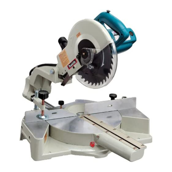
Models No.
Description
C
ONCEPTION AND MAIN APPLICATIONS
The above model is the high power version of the existing
model LS1011. The power input has been increased from 1,380W
to 1,500W.
S
pecification
Voltage (V)
120
Diameter : mm (")
Blade
Arbor : mm (")
No load speed (min
Protection from electric shock
Electric brake
Lock off switch
Cord length : m (ft)
Net weight : Kg (lbs)
Miter angle
Bevel angle
0°
45°
(left)
*When cutting with a wood facing 33mm (1-3/8") thick set between stock and guide fence.
**When cutting with a wood facing 25mm (1-3/16") thick set between stock and guide fence.
***When cutting with a wood facing 20mm (9/16") thick set between stock and guide fence.
S
tandard equipment
* Dust bag ........................ 1 pc.
* Triangular rule .............. 1 pc.
* Socket wrench .............. 1 pc.
< Note > The standard equipment for the tool shown may differ from country to country.
O
ptional accessories
* Holder assembly
* Set plate
* Various saw blades
LS1011N
Slide compound saw 255mm
Dimensions : mm ( " )
Width (W )
Length ( L )
Height ( H )
Cycle (Hz)
Current (A)
50 - 60
13
= rpm)
-1
Capacity : mm (")
0°
(left and right)
75 x 305
(2-15/16 x 8-1/2)
(2-15/16 x 12)
**90 x 165
*90 x 240
**(3-1/2 x 6-1/2)
*(3-1/2 x 9-1/2)
40 x 305
(1-9/16 x 12)
(1-9/16 x 8-1/2)
* Vertical vise ................... 1 pc.
* Lock off button ............ 1 pc. (for spare)
* Carbide-tipped saw blade 25 .............. 1 pc.
* Holder set
510 (20)
542 (21-3/8)
557 (22)
Continuous Rating (W)
Input
1,500
255-260 (10 - 10-1/4)
15.88 (5/8)
5,200
by double insulation
Yes
Yes
2.5 (8.2)
17.2 (38.0)
45°
57°
(right)
75 x 165
75 x 215
(2-15/16 x 6-1/2)
***90 x 125
***(3-1/2 x 4-7/8)
40 x 215
NEW TOOL
L
W
Max. Output(W)
Output
800
2,200
P 1 / 13
H
Advertisement

Related Manuals for Makita LS1011N


Summary of Contents for Makita LS1011N
- Page 1 ECHNICAL INFORMATION NEW TOOL P 1 / 13 Models No. LS1011N Description Slide compound saw 255mm ONCEPTION AND MAIN APPLICATIONS The above model is the high power version of the existing model LS1011. The power input has been increased from 1,380W to 1,500W.
-
Page 2: Features And Benefits
P 2 / 13 eatures and benefits LS1011N Equipped with powerful Convenient Carrying Handle N94 type 1,500W motor for Easy Transport ° bevels (left) Easily operatable lever for Miters up to Comes with dust bag bevel angle adjustment 57° Right and 47° Left Comes with a T. - Page 3 P 3 / 13 epair < 1 > Lubrication Apply MAKITA grease N No.1 to the following parts. * The following portion of blade case on which compression spring rubs. Apply here MAKITA grease N No.1. * The portions marked with black triangle of the following parts.
- Page 4 P 4 / 13 epair < Note > Take off saw blade from the machine for your safety, before repairing or maintenance ! * You can also remove motor section from arm when repairing turn base and base section, if you want. <...
- Page 5 P 5 / 13 epair < 3 > Assembling slide section 1) Pass slide pipe through bearing 30 (integrated part of turn base) as illustrated in Fig 3A. Assemble rubber washer and lock ring 30 to slide pipe as illustrated in Fig. 3B. <...
- Page 6 P 6 / 13 epair 4) After assembling slide guide plate, slide guide support and slide guide, fix rod with adjusting the rolling position of needle bearings 808 and 708. Shown in Fig. 6A and 6B are the correctly assembled parts. Lock ring 30 Rubber washer Turn base...
- Page 7 P 7 / 13 epair 6) Assembling linear ball bearing 3064 1. In this bearing, slide pipe is held with balls which is lined in 6 streaks. Felt ring 30 Put linear ball bearing 3064 on the hole of turn base. Turn base When putting it, the balls have to be located as illustrated...
- Page 8 P 8 / 13 epair 8) Assembling front cover 1. Front cover has to be assembled to turn base as illustrated in Fig. 9A. The surfaces for assembling kerf boards have to be flat. Turn base Turn base Fig. 9 Front cover Fig.
- Page 9 P 9 / 13 epair 3. Disassemble hex bolt M10 x 105, 2 pcs. of flat washers 10 and pipe 16-90. Then, motor section can be removed from arm as illustrated in Fig. 11. Compression spring 28 and spring holder are still locked in blade case with 2 pcs. of round bars in this process. Flat washer 10 Hex lock nut M10 Pipe 16-90...
- Page 10 P 10 / 13 epair Steel ball 6.4 < 4 > Assembling motor section as a jig 1. Put blade case on the turn table of arbor press as illustrated in Fig. 13A. Put compression spring 28 and spring holder in the blade case.
- Page 11 P 11 / 13 epair 3. Assemble link plate by fastening hex socket head bolt M6 x 20 as illustrated in Fig. 13E. And then, take off round bars which were inserted for blocking compression spring 28 and spring holder, as illustrated in Fig. 13D. Round bars for blocking compression spring 28 and spring holder...
- Page 12 P 12 / 13 epair 2. 45° bevel angle Push the motor section to the nearest position to guide rule, and fasten screw M6 x 20 to secure the motor section in the above position. Loosen lever 125 to the direction indicated with arrow as illustrated in Fig. 15A . Tilt the motor section fully to the left.
-
Page 13: Circuit Diagram
P 13 / 13 ircuit diagram Black White Side A Side B Field Yellow Orange Power supply cord Switch Side A Power supply cord side Side B Switch side Switch iring diagram 1. Connect the field lead wires to switch. Fix all of field lead wires with lead holder.
Need help?
Do you have a question about the LS1011N and is the answer not in the manual?
Questions and answers