Table of Contents
Advertisement
Advertisement
Table of Contents

Related Manuals for Makita SLIDE COMPOUND SAW LS1011N


Summary of Contents for Makita SLIDE COMPOUND SAW LS1011N
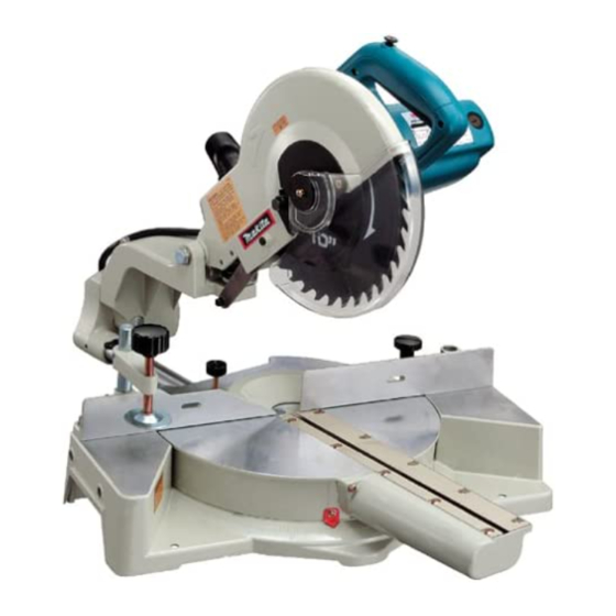
- Page 1 Slide Compound Saw Equipped with Electric Blade Brake 255 mm (10”) MODEL LS1011N I N S T R U C T I O N WARNING: For your personal safety, READ and UNDERSTAND before using. SAVE THESE INSTRUCTIONS FOR FUTURE REFERENCE. w w w .
-
Page 2: Specifications
SPECIFICATIONS Blade diameter : ... 255 mm (10”) Hole diameter : ... 15.88 mm (5/8”) Max. Miter angle : ...Left 45°, Right 57° Max. Bevel angle : ...Left 45° Max. Cutting capacities (H x W) Bevel angle 0° 45° (left) (Note) 1. - Page 3 1. KNOW YOUR POWER TOOL. Read the owner’s manual carefully. Learn the tool’s applications and limitations, as well as the specific potential hazards peculiar to it. 2. KEEP GUARDS IN PLACE and in working order. 3. REMOVE ADJUSTING WRENCHES. Form habit of checking to see that keys and adjusting wrenches are removed from tool before turning it on.
-
Page 4: Additional Safety Rules
23. POLARIZED PLUGS. To reduce the risk of electric shock, this equipment has a polarized plug (one blade is wider than the other). This plug will fit in a polarized outlet only one way. If the plug does not fit VOLTAGE WARNING: Before connecting the tool to a power source (receptacle, outlet, etc.) be sure the voltage supplied is the same as that specified on the nameplate of the tool. - Page 5 4. Do not perform any operation freehand. The workpiece must be secured firmly against the turn base and guide fence with a vise during all operations. Never use your hand to secure the workpiece. 5. Never reach around saw blade. 6.
- Page 6 28. Always use accessories recommended in this manual. Use of improper accessories such as abrasive wheels may cause an injury. 29. NEVER hold workpiece on right side of blade with left hand or vice versa. This is called cross-armed cutting and exposes user to risk of SERIOUS PERSONAL INJURY as shown in the figure.
-
Page 7: Blade Guard
INSTALLATION 002168 1. Stopper Pin 002169 1. Bolt FUNCTIONAL DESCRIPTION 001535 1. Blade guard Bench mounting When the tool is shipped, the handle is locked in the lowered position by the stopper pin. Release the stopper pin by lower- ing the handle slightly and pulling the stopper pin. This tool should be bolted with two bolts to a level and stable surface using the bolt holes provided in the tool’s base. -
Page 8: Positioning Kerf Board
Do not remove spring holding blade guard. If guard becomes discolored through age or UV light exposure, con- tact a Makita service center for a new guard. DO NOT DEFEAT OR REMOVE GUARD. Positioning kerf board This tool is provided with the kerf boards in the turn base to minimize tearing on the exit side of a cut. -
Page 9: Adjusting The Miter Angle
002171 1. Turn base 2. Adjusting bolt 001540 1. Top surface ot turn base 2. Periphery of blade 3. Guide fence 002172 1. Clamp screw 2. Miter scale 3. Pointer Maintaining maximum cutting capacity This tool is factory adjusted to provide the maximum cutting capacity for a 255 mm (10”) saw blade. -
Page 10: Adjusting Bevel Angle
002173 1. Arm 2. Lever 002174 1. Lever 2. Pointer 3. Bevel scale 001551 1. Lock-off button 2. Handle 3. Switch trigger Adjusting the bevel angle To adjust the bevel angle, loosen the lever at the rear of the tool counterclockwise. Push the handle to the left to tilt the saw blade until the pointer points to the desired angle on the bevel scale. -
Page 11: Electric Brake
NEVER use the tool if it runs when you simply pull the switch trigger without pressing the lock-off button. Return tool to a Makita service center for proper repairs BEFORE further usage. •... - Page 12 001858 1. Center cover 2. Socket wrench 3. Hex bolt 4. Blade guard 002859 1. Blade case 2. Arrow 3. Shaft lock 4. Hex bolt 5. Socket wrench 001786 1. Hex bolt 2. Outer flange 3. Saw blade 4. Inner flange 5.
-
Page 13: Securing Workpiece
NOTE: If you connect a Makita vacuum cleaner to your saw, more efficient and cleaner operations can be performed. Securing workpiece WARNING: •... - Page 14 001549 1. Support 2. Turn base 001796 1. Vise arm 2. Vise rod 3. Guide fence 4. Holder 5. Holder assembly 6. Vise knob 7. Screw 002247 1. Holder 2. Holder assembly CAUTION: • When cutting long workpieces, use supports that are as high as the top surface level of the turn base.
-
Page 15: Operation
002246 1. Holder assembly 2. Rod 12 OPERATION 002177 When cutting long workpieces, use the holder-rod assembly (optional accessory). It consists of two holder assemblies and two rods 12. CAUTION: • Always support long workpieces level with the top surface of the turn base for accurate cuts and to prevent dangerous loss of control of the tool. - Page 16 002178 CAUTION: • Firmly tighten the clamp screw on the turn base clockwise so that the carriage will not move during operation. Insufficient tightening may cause unexpected kickback of the blade. Possible serious PERSONAL INJURY may result. 2. Slide (push) cutting (cutting wide workpieces) Loosen the clamp screw on the turn base counterclock- wise so that the carriage can slide freely.
- Page 17 4. Bevel cut 002179 Loosen the lever and tilt the saw blade to set the bevel angle (Refer to the previously covered “Adjusting the bevel angle”). Be sure to retighten the lever firmly to secure the selected bevel angle safely. Secure the work- piece with a vise.
- Page 18 001555 52∞ 45∞ 45∞ 38∞ 45∞ 45∞ 1. 52/38° type crown molding 2. 45° type crown molding 3. 45° type cove molding 001556 (1) (2) (3) (4) Fig.A 1. Inside corner 2. Outside corner 001557 1. Inside corner 2. Outside corner 6.
- Page 19 Example: In the case of cutting 52/38° type crown molding for position (1) in Fig. A: • Tilt and secure bevel angle setting to 33.9° LEFT. • Adjust and secure miter angle setting to 31.6° RIGHT. • Lay crown molding with its broad back (hidden) surface down on the turn base with its CEILING CONTACT EDGE against the guide fence on the saw.
- Page 20 000031 Ceiling 52˚ 38˚ Wall to Crown Molding Angle: 52/38 degrees Wall Angle Bevel Angle Miter Angle (deg.) (deg.) (deg.) 43.0 46.8 42.8 46.3 42.5 45.7 42.2 45.1 41.9 44.6 41.7 44.0 41.4 43.5 41.1 42.9 40.8 42.4 40.5 41.9 40.2 41.3 39.9...
- Page 21 000032 Ceiling 45˚ 45˚ Wall to Crown Molding Angle: 45 degrees Wall Angle Bevel Angle Miter Angle (deg.) (deg.) (deg.) 37.8 50.8 37.5 50.2 37.3 49.6 37.1 49.1 36.8 48.5 36.6 48.0 36.4 47.4 36.1 46.9 35.9 46.4 35.6 45.8 35.4 45.3 35.1...
- Page 22 001844 1. Vise 2. Spacer block 3. Guide fence 4. Aluminum extrusion 5. Spacer block 7. Cutting aluminum extrusion When securing aluminum extrusions, use spacer blocks or pieces of scrap as shown in the figure to prevent deformation of the aluminum. Use a cutting lubricant when cutting the aluminum extrusion to prevent build-up of the aluminum material on the blade.
- Page 23 001846 1. Set plate 2. Holder 3. Screw 001563 1. Cut grooves with blade CAUTION: • Use screws to attach the wood facing to the guide fence. The screws should be installed so that the screw heads are below the surface of the wood facing. •...
-
Page 24: Carrying Tool
002168 1. Stopper Pin 002183 MAINTENANCE CAUTION: • Be sure to return the stopper plate to the original position when performing other than groove cutting. Carrying tool Make sure that the tool is unplugged. Secure the blade at 0° bevel angle and the turn base at right miter angle fully. Secure the slide poles after pulling the carriage toward you fully. - Page 25 002184 1. Guide fence 2. Hex bolts 002185 1. Guide fence 2. Triangular rule 002186 1. Screw 2. Miter scale 3. Pointer 002187 1. Miter angle Push the carriage toward the guide fence and tighten the clamp screw on the turn base to secure the carriage. Loosen the clamp screw on the guide fence which secures the turn base.
- Page 26 002188 1. Lever 2. Arm 3. 0° bevel angle adjusting bolt 001819 1. Triangular rule 2. Saw blade 3. Top surface of turn base 002189 1. Pointer 2. Arm Holder 3. Bevel Scale 002190 1. Pointer 2. Lever 3. 45° bevel angle adjusting bolt 4.
-
Page 27: Replacing Carbon Brushes
10 minutes. Then check the tool while running and electric brake operation when releasing the switch trigger. If electric brake is not working well, ask your local Makita service center for repair. After use •... - Page 28 CAUTION: • These accessories or attachments are recommended for use with your Makita tool specified in this manual. The use of any other accessories or attachments might present a risk of injury to persons. Only use accessory or attachment for its stated purpose.
- Page 29 First-Class Postage Required Post Office will not deliver without proper postage. Makita U.S.A., Inc. 14930 Northam Street La Mirada, CA 90638-5753 Fold...
- Page 30 Paste 3. How did you learn about this product: Magazine From Dealer Newspaper Store Display Catalog 4. Most favored points are: Design Features Size Price Makita Brand MODEL NO. YEAR SERIAL NO. PHONE 20-29 30-39 40-49 Paste Paste Radio Exhibition...
-
Page 31: Factory Service Centers
Date Purchased When you need service: Send complete tool (prepaid) to one Dealer’s Name & Address of the Makita Factory Service Centers listed, or to an Authorized Makita Service Center. Be sure to attach a letter to the outside of Model No. - Page 32 MAKITA LIMITED ONE YEAR WARRANTY Warranty Policy Every Makita tool is thoroughly inspected and tested before leaving the factory. It is warranted to be free of defects from workmanship and materials for the period of ONE YEAR from the date of original purchase.
Need help?
Do you have a question about the SLIDE COMPOUND SAW LS1011N and is the answer not in the manual?
Questions and answers