
Related Manuals for XtendLan SDOMEO4802701


Summary of Contents for XtendLan SDOMEO4802701
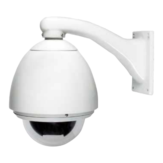
- Page 1 SDOMEO4802701 Outdoor Day/Night Speed Dome with built in Sony CCD 27x optical zoom camera SDOME4802201 Indoor Day/Night Speed Dome with built in Sony CCD 22x optical zoom camera User’s Guide...
- Page 2 Safety Attention Notes ● Please read the instructions thoroughly before installing or operating the unit. ● Please do not put the machine on an unstable table or mounting bracket. ● Please prevent all liquids or other contaminating material from entering into the dome housing.
-
Page 3: Table Of Contents
Contents: Introduction ..........................5 Technical Data ..........................5 Technical Parameter of Intelligent High-speed Dome ..............5 2.2. Camera Parameter for High-speed Dome: ..................6 Setting, Installation, Connection ....................6 Dome Address, Transmission Speed, Protocol Setting ..............6 3.1.1 Speed Dome Camera Address Setting ................... 7 3.1.2 Speed Dome Camera Communication Protocol Setting ............ - Page 4 4.5.1 Zoom Control ........................20 4.5.2 Focus Control ........................20 4.5.3 Iris Control ........................... 20 4.5.4 Auto Backlight Compensation ..................... 20 4.5.5 Auto White Balance ......................20 Camera Menu Setting ....................... 21 Protocol Order Chart ......................... 23 PELCO-D, PELCO-P Protocol Order Chart ..................23 Exception Handling ........................
-
Page 5: Introduction
1 Introduction Congratulations on purchasing our speed dome, an intelligent, high-speed dome camera with a high-performance DSP camera and sophisticated zoom lens. It is an advanced technological surveillance product combining an all-direction variable speed dome and digital decoder all in one unit. It can aim quickly and scan continuously, making omni-directional and non-blind-spot monitoring into reality. -
Page 6: Camera Parameter For High-Speed Dome
2.2 2.2. Camera Parameter for High-speed Dome: Outdoor Day/Night Indoor Speed Model Speed Dome Dome Mode ¼" Sony Exview (Day/Night) CCD ¼" Sony Exview (Day/Night) Scan 2:1 Interlace 2:1 Interlace Resolution >480 lines >480 lines Minimum illumination 0.8lux/0.01lux (b/w mode) 1lux/0.01lux (b/w mode) Iris Auto/manual... -
Page 7: Speed Dome Camera Address Setting
3.1.1 Speed Dome Camera Address Setting The address code for the speed dome should be properly set before use to ensure accurate operating order of the controller at the control centre and to control many dome cameras. The address code is made up of ADD (8 bits) on PCB board. The 8 bits switch uses the 8421 binary coded decimal system. -
Page 8: Speed Dome Camera Communication Protocol Setting
3.1.2 Speed Dome Camera Communication Protocol Setting SW 1 switch: 3.1.3 Speed Dome Camera Transmission Speed Setting (Baud Rate Setting) The 5th and 6th bits of FUN on the PCB board are used to set the baud rate (see following figure). -
Page 9: Installation, Connection
3.2 Installation, Connection Attention! 1. Installation should only be handled by a qualified CCTV expert. 2. For detailed connection information, please refer to silk-screen print instruction on PCB and installation guide or manuals. 3. Because the dome is a high-grade optical unit, please never touch any of the optical components. - Page 10 a. Set wall bracket mounting on the wall. Draw out center site of the hole on the wall against bracket sample b. Use drill to make 4 holes with the M8 size at the designated site. Screw in M8 bolt for mounting c.
- Page 11 Camera Module Installation ● Install under the condition that the power is off ● Loosen the two M5 bolts on the bracket, which are located in the inner housing. ● Take the camera module from the packing, and check if connecting wire plugs are loose. Set code switch of the dome.
-
Page 13: Indoor Hemisphere Dome Camera Recessed Installation
3.2.3 Indoor Hemisphere Dome Camera Recessed Installation ATTN: Installation locations should endure five times the total weight of the camera assembly (dome camera, mounting bracket and mounting base) to avoid in shaken images. Installation ceiling must be strong and has no peeling phenomenon. A. - Page 14 Housing Installation A Take out the housing from the carton, adjust the thickness of bolt reed more than that of ceiling. B Stick 3 rings to housing, and install the upper housing in the round hole of the ceiling, connecting flange edge with the ceiling surface closely. C Use screwdriver to rotate the bolt of the ring, making the ring stick to the ceiling in order to connecting flange edge with the ceiling surface closely.
-
Page 15: Control Keyboard Control Use Instruction To Speed Dome Camera
Connection (Outer Connecting Wire) Connect BNC video interface of dome camera with video wire (BNC) which is finished installing. Connect power supply line with power line (AC24V) which have been set well. Electricity ● Check the polarity of the plug and outlet, then check all connecting wires. ●... -
Page 16: Setting Preset Position
memory. By using this saved parameter, the dome and camera can run to the preset positions when it is required. Operator can save and adjust preset positions by using the control keyboard; the speed dome can support 128 preset positions. 4.1.1 Setting Preset Position Adjust the speed dome camera to the desired position using the keyboard joystick/rocker (including location, camera zoom, focus and iris), and then input the required preset position number. -
Page 17: Preset Position Parameter Setting
4.2.1 Preset Position Parameter Setting speed dome camera has the capacity to set up to 128 preset positions through the keyboard. It can set a running speed at each preset position from 0.4/s to 280/s (1-64grades) and dwell time from (1-60seconds). -
Page 18: Sequence Setting
8. Press Shift+MON to move the cursor back to 1.Position:001← 9. Press CLR to delete 0006 10. Input 02, press Enter 11. Press the Shift+MON key to move the cursor to Speed:64← 12. Press CLR to delete 64 13. Input 10, press Enter 14. -
Page 19: 360° Scan
Input 32 grade, then press AUTO key. This will scan starting at Point A to Point B at a scanning rate of 32 grade stopping at Point A for 2 seconds and Point B for 3 seconds. 4.3.2 360° Scan The Operator can also start an auto cruise scan. -
Page 20: Camera Control
4.5 Camera Control 4.5.1 Zoom Control The user can adjust the advanced zoom feature to acquire needed image through control keyboard. The speed dome features a 216x zoom magnification (18x Optical and 12x Digital). 4.5.2 Focus Control The speed dome’ s default setting is for auto-adjust focusing. Under special conditions, a user can adjust the focus manually meet the required image effect. -
Page 21: Camera Menu Setting
5 Camera Menu Setting Through the control keyboard , you can enter the speed dome camera menu setting. V.1 Camera Menu (LGCamera,CNB Camera,J270zoom Camera) Function Operating Key Set 95 preset postion Enter Camera menu ZoomWide Cursor up ZoomTele Cursor down FocusFar Increase of data(or select the item) FocusNear... - Page 22 4)MIRROR:OFF(Right-Left shift) Press down PAN_A key,status from OFF ON change 5)NEGATIVE:OFF Press down PAN_A key,status from OFF ON change 6)ICR:AUTO(B/W – color auto shift) Press down PAN_A key, status from AUTO(auto) OFF change Then select AUTO status, the Day/Night dome camera will shift B/W image when the illumination is low.
-
Page 23: Protocol Order Chart
6 Protocol Order Chart 6.1 PELCO-D PELCO-P Protocol Order Chart P.S.: PELCO protocol has no relative order in control protocol because of part special function. In order to control some special function of dome, we make function shift to usual function. Usually adopt "adjust preset position/set preset position order"... -
Page 24: Exception Handling
7 Exception Handling Issue Possible Reason Solution Power on, no movement, Power line connected wrong Correct it no image, indicator light Power damaged Replace does not light Blowout Replace Power line be connected bad Check it Power on, self check, has The machine’... - Page 25 Matri Matri Matri BinarySystem;Code PELCO-D Binary System Code PELCO-D Binary System Code PELCO-D PELCO-P PELCO-P PELCO-P 00110000 01011001 10000010 00110001 01011010 10000011 00110010 01011011 10000100 00110011 01011100 10000101 00110100 01011101 10000110 00110101 01011110 10000111 00110110 01011111 10001000 00110111 01100000 10001001 00111000 01100001 10001010...
- Page 26 Matri Matri Matri Binary System Code PELCO-D Binary System Code PELCO-D Binary System Code PELCO-D PELCO-P PELCO-P PELCO-P 10101011 11001000 11100101 10101100 11001001 11100110 10101101 11001010 11100111 10101110 11001011 11101000 10101111 11001100 11101001 10110000 11001101 11101010 10110001 11001110 11101011 10110010 11001111 11101100 10110011...
Need help?
Do you have a question about the SDOMEO4802701 and is the answer not in the manual?
Questions and answers