Table of Contents
Advertisement
Quick Links
Advertisement
Table of Contents

Subscribe to Our Youtube Channel
Related Manuals for XtendLan SDOMEOIR6-CM10


Summary of Contents for XtendLan SDOMEOIR6-CM10
- Page 1 SDOMEOIR6-CM10 SDOMEOIR6W-SD2121 User manual...
- Page 2 WARNINGS AND CAUTIONS WARNING TO REDUCE THE RISK OF FIRE OR ELECTRIC SHOCK, DO NOT EXPOSE THIS PRODUCT TO RAIN OR MOISTURE. DO NOT INSERT ANY METALLIC OBJECTS THROUGH VENTILATION GRILLS OR OPENINGS ON THE EQUIPMENT. CAUTION EXPLANATION OF GRAPHICAL SYMBOLS The lighting flash with arrowhead symbol, within an equilateral triangle, is intended to alert the user the presence of non-insulated “dangerous voltage”...
- Page 3 PRECAUTIONS: 1. Persons without technical qualifications should not attempt to operate this dome device before reading this manual thoroughly. 2. Remove any power to the dome before attempting any operations or adjustments inside the dome cover to avoid potential damage to the mechanism. 3.
- Page 4 IMPORTANT SAFEGUARDS 1. Read these instructions before attempting installation or operation of dome device. 2. Keep these instructions for future reference. 3. Heed all warnings and adhere to electrical specifications. Follow all instructions. 4. Clean only with non abrasive dry cotton cloth, lint free and approved acrylic cleaners. 5.
-
Page 5: Table Of Contents
INDEX Product Introduction ....................... 1 Specification ........................2 Performance Features ......................3 Function Description ......................4 Installation ..........................6 Product Dimension ......................6 Bracket Dimension ......................6 Installation ........................... 7 Connection ......................... 7 Instruction ..........................8 Power On Action......................... 8 Basic Function ........................ -
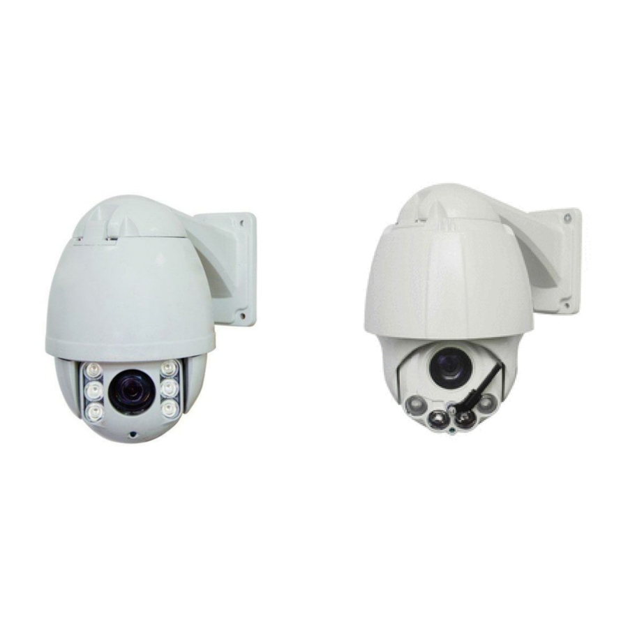
Page 6: Product Introduction
1 Product Introduction 1.1 Specification 0.02°-200°/s Horizontal Rotation Speed 0.02°-120°/s Tilt Rotation Speed 360° Horizontal Rotation Range 93° Tilt Rotation Range Horizontal 180°, Vertical 93° Auto Flip Ratio Speed Support Auto control IR LED IR Testing Time 2-15s selectable Ambient Light Testing 0-50 grades IR Illumination On 0-25 grades selectable... -
Page 7: Performance Features
1.2 Performance Features PWM function. Intelligent IR illumination & power consumption is variable, dependant the zoom factor. 3D allocation. That screen coordinate location and zoom local are performed at the same time can be available. Privacy masking. 24 privacy masking areas can be random set (module support). ... -
Page 8: Function Description
1.3 Function Description Alarm Linkage Intelligent dome camera supports 4 switch alarm inputs, 1 switch output and 1 digital output. When the dome camera has detected the alarm closed signal, it will run the preset action which can be one of the calling preset points or no action. Auto-adaptive to Protocol and Module The dome can auto-adaptive to the multi protocol and most of the module without changing the DIP switch. - Page 9 (4) Targets are behind the glass covered with water droplets or dust; (5) Targets are moving quickly; (6) Monotonous large area targets, such as wall; (7) Targets are too dark or faint. BLC(Back Light Compensation) If the light of background is bright, the target in the picture may appear dark or as a shadow. BLC enhances exposure of the target in the center of the picture.
-
Page 10: Installation
User can set the function or parameter, or check the related information through the OSD. Return to PTZ Function Return dome’s pan and tilt and camera zoom value to the control device. 2 Installation 2.1 Product Dimension 2.2 Bracket Dimension... -
Page 11: Installation
2.3 Installation 2.4 Connection Connection of RS485 Before connecting, please turn off the power and read carefully the instructions of all connected devices. Please use the standard power we supply and don’t lengthen the power cable arbitrarily. Fig 24... -
Page 12: Instruction
3. Instruction 3.1 Power On Action When initializing the system, the operation as left figure will run IR SPEED DOME in 2 seconds. PROTOCOL PELCO-D/P When restoring out-of-factory settings, please wait patiently. COMM 2400.N.8.1 The operation as left figure will run in 1 minute. DOME ID This left figure means initializing the pan/tilt motor of speed MODULE... -
Page 13: Special Function
Press ZOOM- button to make the lens farther and minify the scene. Press ZOOM+ button to make the lens closer and magnify the scene. Focus After FOCUS- button is pressed, the object in vicinity will become clearer while the object far away will become ambiguous. -
Page 14: Screen Character Operation
3.4 Screen Character Operation Call preset 95 to enter the OSD, call preset 94 to exit the OSD. Up or Down: Move the option of the OSD, change the value on the OSD. Right: Enter the option, select the item or confirm. ... -
Page 15: Osd Menu
4 OSD Menu... -
Page 16: System
4.1 System <SYSTEM> <MAIN MENU> PROTOCOL: Display the protocol of the dome. <SYSTEM> COMM: 2400. N. 8. 1 means the communication <DOME> information. 2400 is baud rate. COMM form: Baud rate. <CAMERA> Check bit. Data bit. Start bit. <IR>... -
Page 17: Scan
back. <PRESET> PRESET NO Because some presets are used to realize special CALL PRESET functions, they can not be set and called normally. <SET PRESET> PRESET 1: SAVE PRESET 2: BACK 4.2.2 Scan SCAN SPEED: Scan speed includes setting the SCAN speed of limited points scan (A-B scan) and SCAN SPEED... -
Page 18: Pattern
4.2.4 Pattern PATTERN NO: Factory default is 1. <PATTERN> Select the pattern needing to be edited. 1-4 pattern are PATTERN NO effective. CALL PATTERN <PATTERN> CALL PATTERN: Call the patterns having been EXIT edited. <PATTERN> <PATTERN> Left figure shows the status when entering to the pattern set. PATTERN NO “XXX”... -
Page 19: Other
4.2.6 Other PARK MODE: There are 13 actions of NONE, Pattern 1, Tour 1, 360 scan, AB scan, Preset 1-8 <DOME> selectable. <PRESET> <SCAN> PARK TIME: The dome camera runs home <GUARD TOUR> position after a period of idle time which is home time <PATTERN>... -
Page 20: Camera
4.3 Camera ZOOM LIMIT: Display the maximum zoom position, <CAMERA> which relates to that digital zoom is OFF or ON. ZOOM LIMIT FOCUS MODE AUTO FOCUS MODE: Auto and manual are selectable. DIGITAL ZOOM DIGITAL ZOOM: Digital zoom ZOOM SPEED HIGH... -
Page 21: Display
4.4 IR IR MODE: It has auto, small light on, large light on, <IR> manual and off selectable. IR MODE AUTO OUTPUT POWER: Its selectable range is 1-9 OUTPUT POWER level. TESTING TIME TESTING TIME: Its settable range is 2-15S. STANDBY POWER ... -
Page 22: Time
TIME: Set the system time. -
Page 23: Language
SCHEDULE: Action: There are preset 1-8, A-B scan, 360°scan, guard tour preset, pattern, no action selectable. Example of Schedule: <SCHEDULE> 1: 8 schedules can be set. First, select the schedule needing START to be set and press the right key to enter the setting status. 00:00:00 00:00:00 NONE... -
Page 24: Appendix Ⅰ Anti-Lightning, Anti-Surges
Appendix Ⅰ Anti-lightning, Anti-surges This product is extremely air discharge and lightning protection with TVS tube technology, which can effectively prevent the transient lightning below voltage 6000V, surge and damages caused by other types of pulse signals. However, necessary protective measures should be made in the premise of ensuring electrical safety for outdoor installation according to the actual situation : ·Signal transmission line must be at least 50 meters far away from the high-voltage equipment or high voltage cable. -
Page 25: Appendix Ⅲ Common Knowledge On Rs-485 Bus
● Please use a soft enough dry cloth or other alternatives to wipe internal and external surface. ● If dirt is serious, user can use a mild detergent. Any senior furniture cleaning products can be used to clean the under cover. Appendix Ⅲ... -
Page 26: Appendix Ⅳ Exception Handling
Appendix Ⅳ Exception Handling Issue Possible Reason Solution After power is applied, Cable harness is improperly Verify that the orientation of the connected connector input there is no action Input power voltage is too low Verify the voltage of the input power (self-test) and no video image.
Need help?
Do you have a question about the SDOMEOIR6-CM10 and is the answer not in the manual?
Questions and answers