
Subscribe to Our Youtube Channel
Related Manuals for LSI LSIU80ALVD


Summary of Contents for LSI LSIU80ALVD
- Page 1 USER’S GUIDE LSIU80ALVD PCI to Ultra2 SCSI Host Adapter A u g u s t 2 0 0 4 Version 2.0 ® DB15-000320-00...
-
Page 2: Electromagnetic Compatibility Notices
Consult the dealer or an experienced radio/TV technician for help. Shielded cables for SCSI connection external to the cabinet are used in the compliance testing of this Product. LSI Logic is not responsible for any radio or television interference caused by unauthorized modification of this equipment or the substitution or attachment of connecting cables and equipment other than those specified by LSI Logic. - Page 3 LSI Logic; nor does the purchase or use of a product from LSI Logic convey a license under any patent rights, copyrights, trademark rights, or any other of the intellectual property rights of LSI Logic or third parties.
- Page 5 Preface This book is the primary reference and user’s guide for the LSIU80ALVD PCI to Ultra2 SCSI Host Adapter. It contains a complete functional description for the LSIU80ALVD and includes complete physical and electrical specifications for the LSIU80ALVD. Audience This document assumes that you have some familiarity with microprocessors and related support devices.
- Page 6 Related Publications PCI Storage Device Management System SDMS™ 4.0 User’s Guide, Document DB15-000099-01 Revision Record Revision Date Remarks 8/04 Final version. First printing. Preface...
-
Page 7: Table Of Contents
Contents Chapter 1 Using the LSIU80ALVD General Description Features 1.2.1 1.2.2 1.2.3 Interface Descriptions 1.3.1 1.3.2 1.3.3 1.3.4 1.3.5 Chapter 2 Installing the LSIU80ALVD Quick Installation Procedure Detailed Installation Procedure 2.2.1 2.2.2 2.2.3 2.2.4 2.2.5 2.2.6 2.2.7 2.2.8 2.2.9 2.2.10... - Page 8 Chapter 3 Configuring the LSIU80ALVD When to Configure the LSIU80ALVD Starting the SCSI BIOS Configuration Utility 3.2.1 3.2.2 3.2.3 Exiting the SCSI BIOS Configuration Utility Appendix A Technical Specifications Physical Environment A.1.1 A.1.2 A.1.3 A.1.4 A.1.5 Operational Environment A.2.1 A.2.2 A.2.3...
- Page 9 Figures 2.10 2.11 2.12 2.13 2.14 Contents Hardware Connections for the LSIU80ALVD Inserting the Host Adapter SCSI Cables Internal SCSI Ribbon Cable to Host Adapter Connection Internal SCSI Ribbon Cable to Internal SCSI Device Connection Connecting Additional Internal SCSI Devices...
- Page 10 Contents...
- Page 11 Tables Contents SCSI Bus Widths and Speeds SCSI Bus Lengths SCSI ID Record Global Default Settings Device Default Settings Maximum Power Requirements PCI Connector J1 (Front) PCI Connector J1 (Back) Internal SCSI Connector J2 External SCSI Connector J3 LED Connector J4 2-23 A-10...
- Page 12 Contents...
-
Page 13: Using The Lsiu80Alvd
Section 1.3, “Interface Descriptions,” page 1-3 General Description The LSIU80ALVD provides an Ultra2 SCSI interface to PCI computer systems. It will be referred to as the LSIU80ALVD throughout this manual. Installing this adapter in your PCI system allows connection of up to 15 SCSI devices. -
Page 14: Features
Features This section provides a high level overview of the PCI Interface, the SCSI Interface, and Board Characteristics for the LSIU80ALVD. 1.2.1 PCI Interface Full 32-bit DMA bus master Zero wait-state bus master data bursts up to 133 Mbytes/s (@ 33 MHz) Universal 3.3 V and 5 V PCI bus voltage support... -
Page 15: Board Characteristics
PCI is a high-speed standard local bus for interfacing a number of I/O components to the processor and memory subsystems in equipment ranging from PCs to servers. The PCI functionality for the LSIU80ALVD is contained within the LSI53C895A. The LSI53C895A connects directly to the PCI bus and generates signal timing and bus protocol in compliance with the PCI Specification Revision 2.1. -
Page 16: The Scsi Interface
The LSIU80ALVD supplies SCSI bus TERMPWR through a blocking diode and a self-resetting 1.5 A short circuit protection device. A 40 MHz oscillator is installed on the LSIU80ALVD to provide the clock frequency to the LSI53C895A that is necessary to support Ultra2 SCSI transfers of up to 80 Mbytes/s. -
Page 17: Ultra2 Scsi Technology
1.3.3 Ultra2 SCSI Technology The LSIU80ALVD fully supports Ultra2 SCSI. Ultra2 SCSI is an extension of the SCSI Parallel Interface 2 and 3 (SPI-2 and SPI-3) family of standards that expands the bandwidth of the SCSI bus, allowing faster synchronous data transfers. -
Page 18: On-Board Led
On-board LEDs are used to indicate the status of the SCSI bus. The SCSI Activity LED lights when the SCSI bus is transferring information. Using the LSIU80ALVD To utilize Ultra2 SCSI performance, the user must only have LVD devices on the bus. Do not mix any SE devices with LVD devices as the entire bus will drop to SE with maximum Ultra SCSI performance. -
Page 19: Installing The Lsiu80Alvd
Chapter 2 Installing the LSIU80ALVD This chapter provides instructions on how to install the LSIU80ALVD and includes these topics: Section 2.1, “Quick Installation Procedure,” page 2-1 Section 2.2, “Detailed Installation Procedure,” page 2-3 Section 2.3, “Completing the Installation,” page 2-24... - Page 20 Step 10. Replace the cabinet cover as described in the user’s manual for Step 11. Make all external SCSI bus connections. Finally, refer to the Remember: The SCSI bus requires proper termination, and no duplicate Installing the LSIU80ALVD LSIU80ALVD requires a PCI slot that allows bus master operation. See Table 2.2.
-
Page 21: Detailed Installation Procedure
Detailed Installation Procedure This section provides step-by-step instructions for installing the LSIU80ALVD, and connecting it to your SCSI peripherals. If you are experienced in these tasks, you may prefer to use the preceding 2.1, “Quick Installation Procedure.” perform the tasks as described here, LSI Logic suggests getting assistance. -
Page 22: Inserting The Host Adapter
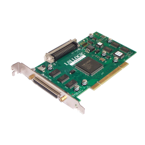
Step 4. Locate the slots for PCI plug-in board installation. Refer to the Step 5. Remove the blank bracket panel on the back of the computer Installing the LSIU80ALVD Remove the LSIU80ALVD from the packing and check that it is not damaged. An example of this host adapter board is shown Figure 2.1. -
Page 23: Hardware Connections For The Lsiu80Alvd
Figure 2.1 Hardware Connections for the LSIU80ALVD Internal SCSI Interface External SCSI Interface Step 6. Carefully insert edge connector J1 (see Note: Detailed Installation Procedure LSIU80ALVD J1 to PCI Mainboard adapter into the PCI slot. Make sure the edge connector is... -
Page 24: Inserting The Host Adapter
Inserting the Host Adapter Bracket Screw Press Here Step 7. The bracket around connector J3 (see Installing the LSIU80ALVD where you removed the blank panel. Secure it with the bracket screw (see Figure 2.2) before making the internal and external SCSI bus connections. -
Page 25: Connecting The Scsi Peripherals
2.2.3 Connecting the SCSI Peripherals SCSI bus connections to the LSIU80ALVD inside your computer can be made with an unshielded 68-conductor Ultra SCSI PVC ribbon cable (see Figure to indicate pin 1. Sometimes the connectors on this cable are keyed to ensure proper pin-1 connection. - Page 26 Wide Ultra2 SCSI 1. This parameter may be exceeded in point-to-point and engineered applications. 2. Additional spacing rules apply. 3. SE and high power differential are not defined at Ultra2 speeds. Installing the LSIU80ALVD SCSI Bus Lengths Maximum Bus Length, Meters Differential –...
-
Page 27: Scsi Cables
Figure 2.3 SCSI Cables Terminated SCSI Cable for Internal Connections (for use with nonterminated internal devices) Terminated End SCSI Cable for Internal Connections SCSI Cable for External Connections Detailed Installation Procedure 68-pin High Density 68-pin High Density 68-pin... -
Page 28: Making Internal Scsi Bus Connections
This section provides step-by-step instructions about making internal SCSI bus connections. Step 1. To connect an internal SCSI device, plug the 68-pin connector Figure 2.4 2-10 Installing the LSIU80ALVD on one end of the internal SCSI ribbon cable into connector J2 (see Figure 2.4). -
Page 29: Internal Scsi Ribbon Cable To Internal Scsi Device Connection
Step 2. Plug the 68-pin connector on the other end of the internal SCSI Note: Figure 2.5 Internal SCSI Ribbon Cable to Internal SCSI Device Connection Detailed Installation Procedure ribbon cable into the SCSI connector on your internal SCSI device. An example of this connection is shown in You must match pin 1 on all connections. -
Page 30: Connecting Additional Internal Scsi Devices
Step 3. To plug in additional internal SCSI devices, use an internal Figure 2.6 Connecting Additional Internal SCSI Devices 2-12 Installing the LSIU80ALVD SCSI ribbon cable with the required number of 68-pin connectors attached along its length as shown in An example of this type of chained connection is shown in Figure 2.7. -
Page 31: Multiple Internal Scsi Devices Chained Together
Figure 2.7 Multiple Internal SCSI Devices Chained Together Detailed Installation Procedure 2-13... -
Page 32: Scsi Led Connector
J4. If the LED does not light during SCSI bus activity from this host adapter, you may have to rotate the LED cable connector 180 on J4. 2-14 Installing the LSIU80ALVD SCSI LED Connector Connector... -
Page 33: Making External Scsi Bus Connections
2.2.5 Making External SCSI Bus Connections This section provides step-by-step instructions about making external SCSI bus connections. Step 1. To connect external SCSI devices to the LSIU80ALVD, plug the Figure 2.9 External Cable to Host Adapter Detailed Installation Procedure 68-pin HD connector on one end of a shielded external SCSI... -
Page 34: External Scsi Device Cable
Step 2. Plug the 68-pin connector on the other end of the shielded Figure 2.10 External SCSI Device Cable 2-16 Installing the LSIU80ALVD external SCSI cable into the SCSI connector on your external SCSI device. An example of this connection is shown in Figure 2.10. -
Page 35: Multiple External Scsi Devices Chained Together
Step 3. To connect more than one external SCSI device to the host adapter, you must chain them together with shielded external SCSI cables. An example of these chained connections is shown in Figure 2.11. Figure 2.11 Multiple External SCSI Devices Chained Together Detailed Installation Procedure HD Connectors 2-17... -
Page 36: Scsi Bus Termination
SCSI bus must have their terminators active. All other SCSI devices on the bus must have their terminators removed or disabled. Remember that the LSIU80ALVD is also on the SCSI bus—its termination is automatically enabled when it is connected to the end of the bus. -
Page 37: Internal Bus Connections
2.2.7 Internal Bus Connections If you have only internal SCSI device connections to your host adapter, you must terminate the last internal device on the SCSI bus. You must disable the terminators on all other devices. Termination on your host adapter is automatically enabled in this case. -
Page 38: External Bus Connections
SCSI bus configuration. Figure 2.13 External SCSI Device Termination Last Device on Bus – Terminators Enabled 2-20 Installing the LSIU80ALVD shows an example of how termination is determined for this Does not end Bus – Terminators Disabled Host Adapter Automatically... -
Page 39: Internal And External Bus Connections
2.2.9 Internal and External Bus Connections If internal and external SCSI device connections to your host adapter have been made, then terminate the last internal and last external devices on the SCSI bus. You must disable the termination on all other devices. -
Page 40: 2.2.10 Setting Scsi Ids
ID other than 0 (zero) can be used. Chapter 3, “Configuring the LSIU80ALVD,” adapter ID using the LSI Logic SCSI BIOS Configuration Utility. The peripheral device SCSI IDs are usually set with jumpers or with a switch on the peripheral. -
Page 41: Scsi Id Record
Table 2.3 SCSI ID Record SCSI ID SCSI Device LSIU80ALVD (default) Detailed Installation Procedure 2-23... -
Page 42: Completing The Installation
Step 2. Plug in all power cords, and switch on power to all devices and Step 3. Wait for your computer to boot up. Step 4. To change the configuration of the host adapter, see 2-24 Installing the LSIU80ALVD your computer. “Configuring the LSIU80ALVD.” Device Management System SDMS 4.0 User’s Guide (or the guide for the software you plan to use) to load the driver software for your particular operating system. -
Page 43: Configuring The Lsiu80Alvd
Chapter 3 Configuring the LSIU80ALVD This chapter describes configuring the LSIU80ALVD and includes these topics: Section 3.1, “When to Configure the LSIU80ALVD,” page 3-1 Section 3.2, “Starting the SCSI BIOS Configuration Utility,” page 3-2 Section 3.3, “Exiting the SCSI BIOS Configuration Utility,” page 3-14 When to Configure the LSIU80ALVD... -
Page 44: Starting The Scsi Bios Configuration Utility
You can see the version number of your LSI Logic SCSI BIOS in a banner displayed on your computer monitor during boot. If the utility is available, the following message also appears on your monitor: Press Ctrl-C to start LSI Logic Configuration Utility... -
Page 45: Configuration Utility Main Menu
Configuration Utility Main Menu When you start the LSI Logic SCSI BIOS Configuration Utility, the Main Menu appears. This menu displays a list of up to four LSI Logic PCI to SCSI host adapters and information about each of them. To select an adapter, use only the arrow keys and enter key. -
Page 46: Main Menu
SCSI devices attached to it. When this option is used to make a change, the change takes place after a reboot upon exit from the utility. Figure 3.2 menu: Configuring the LSIU80ALVD Main Menu Port Irq---------Status--------NVRAM Level Current... -
Page 47: Change Status On Next Boot Menu
Adapter Boot Order Adapter Boot Order allows the user to set the order in which host adapters will boot when you have more than one LSI Logic host adapter in your system. When this option is selected, the Boot Order menu appears. -
Page 48: Adapter Configuration Menu
If enabled, the Language option allows the user to select from five languages for the Configuration Utility: English, German, French, Italian, and Spanish. Call for support if you have any additional questions. Configuring the LSIU80ALVD Adapter Configuration Menu DevFunc BootSeq Figure 3.4) appears:... -
Page 49: Utilities Menu
3.2.1.7 Help The Help option displays a help screen with information about the Main Menu. 3.2.1.8 Quit The Quit option allows exiting from the SCSI BIOS Configuration Utility when the Main Menu is displayed. 3.2.1.9 Pressing the Esc key allows exiting from all the screens except the Main Menu. -
Page 50: Adapter Setup Menu
The settings in this menu are global settings that affect the selected host adapter and all SCSI devices attached to it. SCAM Support – The LSI Logic BIOS Version 4.0 and above supports the SCSI Plug and Play protocol called SCAM. SCAM support by default is off in versions 4.09.00 and later for the LSI53C895A device. - Page 51 Host SCSI ID – This option refers to the host adapter’s SCSI ID, which is a unique number used to identify the device on the SCSI bus. Note: In general, it is suggested that you do not change your host adapter ID from the default value of 7, as this gives it the highest priority on the SCSI bus.
-
Page 52: Device Selections Menu
Termination – This option allows the user to have termination control providing an adapter has controllable termination. The default value is Autotermination. The alternate value is Off. 3-10 Configuring the LSIU80ALVD Neither of these options will have any affect after the disk has been partitioned with the FDISK command. below. -
Page 53: Device Selections Menu
3.2.3 Device Selections Menu When you select the Device Selections option, the corresponding menu appears. Figure 3.7 Device Selections 0-7 0-Dev0 N/A 1-Dev1 N/A 2-Dev2 N/A 3-Dev3 N/A 4-Dev4 N/A 5-Dev5 N/A 6-Dev6 N/A LSI53C895A Device Selections 8-15 Help Exit this menu The settings in this menu affect individual SCSI devices attached to the selected host adapter. - Page 54 Some devices run faster with disconnects enabled (typically newer devices), while some run faster with disconnects disabled (typically older devices). 3-12 Configuring the LSIU80ALVD Device Selections Menu (Cont.) Sync Rate Width Disconnect...
- Page 55 Read/Write I/O Time-Out (seconds) – This option sets the amount of time the host adapter waits for a read, write, or seek command to complete before trying the I/O transfer again. Since this provides a safeguard allowing the system to recover if an I/O operation fails, it is recommended that you always set the time-out to a value greater than zero.
-
Page 56: Exiting The Scsi Bios Configuration Utility
Configuration Utility properly. Return to the Main Menu and exit by using the Quit option. Important: 3-14 Configuring the LSIU80ALVD Rebooting the system without properly exiting from this utility may cause some changes to not take effect. -
Page 57: Technical Specifications
FCC. A.1.1 Physical Characteristics The dimensions of the LSIU80ALVD board are 154.4 x 88.90 mm (6.00 x 3.50 inches). PCI connection is made through edge connector J1. Internal SCSI connection is made through the 68-pin HD connector J2. -
Page 58: Electrical Characteristics
• J4: 4-pin low density connector. A.1.2 Electrical Characteristics The LSIU80ALVD maximum power requirement, including SCSI TERMPWR, under normal operation is as follows: Table A.1 +5 V DC Under abnormal conditions such as a short on SCSI TERMPWR, + 5 V current may be higher. -
Page 59: Thermal, Atmospheric Characteristics
The PCI PRSNT1/ and PRSNT2/ pins are set to indicate a 7.5 W maximum configuration. A.1.3 Thermal, Atmospheric Characteristics The board is designed to operate in an environment defined by the following parameters: Temperature range: 0 C to 55 C (dry bulb) Relative humidity range: 5% to 90% noncondensing Maximum dew point temperature: 32 C Storage Temperature:... -
Page 60: A.2 Operational Environment
A.2 Operational Environment The LSIU80ALVD is designed for use in PCI computer systems. The SDMS operates the board, but the design of the board does not prevent the use of other software. A.2.1 The PCI Interface The PCI interface operates as a 32-bit DMA bus master. The connection is made through edge connector J1, which provides connections on both the front and back of the board. -
Page 61: Pci Connector J1 (Front
Table A.2 PCI Connector J1 (Front) Signal Name 12 V +5 V +5 V INTB/ INTD/ GND (PRSNT1/) RESERVED GND (PRSNT2/) KEYWAY KEYWAY RESERVED REQ/ VI/O AD31 AD29 1. Highlighted signals are not connected. Operational Environment Signal Name AD27 AD25 +3.3 V C_BE3/ AD23... -
Page 62: Pci Connector J1 (Back
Table A.3 PCI Connector J1 (Back) Signal Name TRST/ +12 V +5 V INTA/ INTC/ +5 V RESERVED +5 V RESERVED KEYWAY KEYWAY RESERVED RST/ VI/O GNT/ RESERVED AD30 +3.3 V Note: Highlighted signals are not connected. Technical Specifications Signal Name AD28 AD26 AD24... -
Page 63: The Scsi Interface
A.2.2 The SCSI Interface The SCSI interface conforms to ANSI X 3T10.11/1142. The SCSI interface operates as 16-bit, synchronous or asynchronous, SE or LVD, and supports SCSI-3 protocols and 8-bit and16-bit arbitration. The interface is made through connectors J2 and J3. Active SE or LVD SCSI termination is provided automatically. -
Page 64: Internal Scsi Connector J2
Table A.4 Signal Name SD12+ SD13+ SD14+ SD15+ SDP1+ SD00+ SD01+ SD02+ SD03+ SD04+ SD05+ SD06+ SD07+ SDP0+ DIFFSENS TERMPWR TERMPWR SATN+ SBSY+ SACK+ SRST+ SMSG+ SSEL+ SCD+ SREQ+ SIO+ SD08+ SD09+ SD10+ SD11+ Technical Specifications Internal SCSI Connector J2 Signal Name SD12 SD13... -
Page 65: External Scsi Connector J3
Table A.5 External SCSI Connector J3 Signal Name SD12+ SD13+ SD14+ SD15+ SDP1+ SD00+ SD01+ SD02+ SD03+ SD04+ SD05+ SD06+ SD07+ SDP0+ DIFFSENS TERMPWR TERMPWR SATN+ SBSY+ SACK+ SRST+ TERMPWR TERMPWR SATN SBSY SACK SRST Note: When operated in the SE mode, all signals with the + suffix are clamped to ground. -
Page 66: On-Board Led
A.2.4 The SCSI Busy LED The SCSI Activity LED interface on the LSIU80ALVD is a four-wire arrangement that allows the user to connect an LED harness to the board. The buffered GPIO0_FETCH line (maximum output low voltage 0.4 V and minimum output low current 16 mA) is pulled low to complete the circuit when a harness with an LED is attached. -
Page 67: Appendix B Glossary Of Terms And Abbreviations
A special international committee on radio interference (Committee, International and Special, for Protection in Radio). Configuration Refers to the way a computer is set up; the combined hardware components (computer, monitor, keyboard, and peripheral devices) that LSIU80ALVD PCI to Ultra2 SCSI Host Adapter... - Page 68 make up a computer system; or the software settings that allow the hardware components to communicate with each other. Central Processing Unit. The “brain” of the computer that performs the actual computations. The term Microprocessor Unit (MPU) is also used. Direct Memory Access.
- Page 69 File A named collection of information stored on a disk. Firmware Software that is permanently stored in ROM. Therefore, it can be accessed during boot time. Hard Disk A disk made of metal and permanently sealed into a drive cartridge. A hard disk can store very large amounts of information.
- Page 70 Main Memory The part of a computer’s memory which is directly accessible by the CPU (usually synonymous with RAM). Mbyte Megabyte. A measure of computer storage equal to 1024 kilobytes. Motherboard See Mainboard. In some countries, the term Motherboard is not appropriate.
- Page 71 CPU. Information can be written to and read from RAM. The contents of RAM are lost when the computer is turned off. RISC Core LSI Logic SCSI chips contain a RISC (Reduced Instruction Set Computer) processor, programmed through microcode scripts. Read Only Memory. Memory from which information can be read but not changed.
- Page 72 SCRIPTS processor fetches SCRIPTS instructions from system memory to control operation of the LSI53C8XX device. SDMS Storage Device Management System. An LSI Logic software product that manages SCSI system I/O. Single-Ended A hardware specification for connecting SCSI devices. It references each SCSI SCSI signal to a common ground.
- Page 73 Ultra SCSI A standard for SCSI data transfers. It allows a transfer rate of up to 20 Mbytes/s over an 8-bit SCSI bus and up to 40 Mbytes/s over a 16-bit SCSI bus. STA (SCSI Trade Association) supports using the term “Ultra SCSI”...
- Page 74 Glossary of Terms and Abbreviations...
- Page 75 3-13 width 3-12 disconnect 3-12 display mode duplication of SCSI IDs 2-22 LSIU80ALVD PCI to Ultra2 SCSI Host Adapter edge connector electrical characteristics electromagnetic compliance erroneous termination 2-18 esc key option exit this menu 3-14 exiting the configuration utility...
- Page 76 logical units (LUNs) 3-13 LVDlink technology main menu display main menu options display mode esc key help language mono/color quit multiple internal SCSI devices 2-13 operational environment parity PCI connector J1 (back) PCI connector J1 (front) PCI interface 1-2, 1-3, peripheral device SCSI IDs 2-22 peripheral device terminators...
-
Page 77: Customer Feedback
Please include your name, phone number, fax number, and company address so that we may contact you directly for clarification or additional information. Thank you for your help in improving the quality of our documents. LSIU80ALVD PCI to Ultra2 SCSI Host Adapter... - Page 78 Reader’s Comments Fax your comments to: Please tell us how you rate this document: LSIU80ALVD PCI to Ultra2 SCSI Host Adapter User’s Guide. Place a check mark in the appropriate blank for each category. Completeness of information Clarity of information Ease of finding information...
Need help?
Do you have a question about the LSIU80ALVD and is the answer not in the manual?
Questions and answers