Table of Contents
Advertisement
Quick Links
Advertisement
Table of Contents

Related Manuals for LSI LSI8751D


Summary of Contents for LSI LSI8751D
- Page 1 USER’S GUIDE LSI8751D PCI to SCSI Host Adapter Version 3.0 A u g u s t 2 0 0 1 ®...
-
Page 2: Electromagnetic Compatibility Notices
Consult the dealer or an experienced radio/TV technician for help. Shielded cables for SCSI connection external to the cabinet are used in the compliance testing of this Product. LSI Logic is not responsible for any radio or television interference caused by unauthorized modification of this equipment or the substitution or attachment of connecting cables and equipment other than those specified by LSI Logic. - Page 3 LSI Logic; nor does the purchase or use of a product from LSI Logic convey a license under any patent rights, copyrights, trademark rights, or any other of the intellectual property rights of LSI Logic or third parties.
- Page 5 Preface This book is the primary reference and user’s guide for the LSI Logic LSI8751D PCI to SCSI Host Adapter. It describes how to install and configure the LSI8751D in a PCI computer system. Basic information on setting up the SCSI bus is also provided.
- Page 6 3/99 Document converted to LSI format. 11/00 All product names changed from SYM to LSI. 8/01 Updated Table 3.4 SCSI Connector J2 and J3; Removed the chapter about the SCSI BIOS Configuration Utility; Moved Appendix A to Chapter 3. Other minor updates made to installation instructions in Chapter 2.
-
Page 7: Table Of Contents
Contents Chapter 1 Describing the LSI8751D General Description Features 1.2.1 1.2.2 1.2.3 1.2.4 Chapter 2 Installing the LSI8751D Quick Installation Procedure Detailed Installation Procedure 2.2.1 2.2.2 2.2.3 2.2.4 2.2.5 Completing the Installation Chapter 3 Technical Specifications Physical Environment 3.1.1 3.1.2 3.1.3... - Page 8 Appendix A Glossary of Terms and Abbreviations Customer Feedback Contents...
- Page 9 Figures 2.10 2.11 2.12 2.13 2.14 Hardware Connections for the LSI8751D Inserting the Host Adapter SCSI Cables Internal SCSI Ribbon Cable to Host Adapter Connection Internal SCSI Ribbon Cable to Internal SCSI Device Connection Connecting Additional Internal SCSI Devices Multiple Internal SCSI Devices Chained Together...
- Page 11 Tables SCSI Bus Widths and Speeds SCSI ID Record Maximum Power Requirements PCI Connector JI (Top) PCI Connector JI (Bottom) SCSI Connectors J2 and J3 LED Connector J4 2-20...
-
Page 13: Chapter 1 Describing The Lsi8751D
This guide and the PCI Storage Device Management System SDMS 4.0 User’s Guide contain product information and installation instructions. This information helps you gain the full benefits of the LSI8751D for your computer system. LSI8751D PCI to SCSI Host Adapter... -
Page 14: Features
PCI Local Bus Specification, Revision 2.1 compliance 1.2.2 SCSI Interface The SCSI functionality for the LSI8751D is contained within the LSI53875 controller chip. The LSI53C875 connects directly to the SCSI bus and generates timing and protocol in compliance with the SCSI standard. -
Page 15: Board Characteristics
Universal 32-bit card edge connector 1.2.4 Ultra SCSI The LSI8751D has full support for Ultra SCSI and simultaneously supports Fast SCSI. Ultra SCSI is an extension of the SCSI-3 family of standards that expands the bandwidth of the SCSI bus, allowing faster synchronous data transfers. - Page 16 Describing the LSI8751D...
-
Page 17: Chapter 2 Installing The Lsi8751D
Step 1. Ground yourself before handling this host adapter board, then Note: Step 2. Remove the LSI8751D from the packing and check that it is not Step 3. Turn off and unplug your system. Step 4. Open your PC cabinet. -
Page 18: Detailed Installation Procedure
2.2 Detailed Installation Procedure This section provides step-by-step instructions for installing the LSI8751D and connecting it to your SCSI peripherals. If you are experienced in these tasks, you may prefer to use the instructions in the preceding 2.2.1 Before You Start... -
Page 19: Inserting The Host Adapter
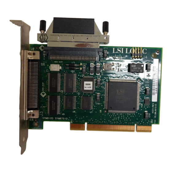
Step 2. Switch off and unplug power cords for all components in your Step 3. Remove the cabinet cover on your computer to access the PCI Caution: Detailed Installation Procedure Remove the LSI8751D from the packing and check that it is not damaged. Figure 2.1 shows an example of this board. -
Page 20: Inserting The Host Adapter
The use of a static ground strap is recommended. user’s manual for your computer to confirm the location of the PCI slots. The LSI8751D requires a PCI slot which allows bus master operation. with the PCI slot you intend to use. Save the bracket screw. -
Page 21: Connecting The Scsi Peripherals
Step 7. The bracket around the connectors J3 (see 2.2.3 Connecting the SCSI Peripherals SCSI bus connections to the LSI8751D inside your computer are made with an unshielded, 68-conductor ribbon cable (see of this cable is marked with a color to indicate the pin-1 side. Sometimes the connectors on this cable are keyed to ensure proper pin-1 connection. -
Page 22: Scsi Cables
Figure 2.3 SCSI Cables SCSI Cable for Internal Connections SCSI Cable for External Connections Installing the LSI8751D... -
Page 23: Internal Scsi Ribbon Cable To Host Adapter Connection
2.2.3.1 Making Internal SCSI Bus Connections This section provides step-by-step instructions for making internal SCSI bus connections: Step 1. To connect an internal SCSI device, plug the 68-pin connector Figure 2.4 Detailed Installation Procedure on one end of the internal SCSI ribbon cable into the connector J2. -
Page 24: Connecting Additional Internal Scsi Devices
Step 2. Plug the 68-pin connector on the other end of the internal SCSI Figure 2.5 Step 3. Connect additional internal SCSI devices by using an internal Figure 2.6 Installing the LSI8751D ribbon cable into the SCSI connector on your internal SCSI device. (See Figure 2.5.) Make sure to match pin 1 on all connections. -
Page 25: Multiple Internal Scsi Devices Chained Together
Figure 2.7 shows an example of this type of chained connection. Make sure to match pin 1 on all connections. Figure 2.7 Multiple Internal SCSI Devices Chained Together Detailed Installation Procedure... -
Page 26: Scsi Led Connector
SCSI bus activity from this host adapter, you may have to rotate the LED cable 180 on J4. 2-10 Installing the LSI8751D may already be connected to an existing IDE drive. Connect this LED cable to connector J4 on the host adapter, as shown Figure 2.8. -
Page 27: External Cable To Host Adapter
2.2.3.2 Making External SCSI Bus Connections This section provides step-by-step instructions for making external SCSI bus connections: Step 1. To connect external SCSI devices to the LSI8751D, plug the 68- Figure 2.9 Detailed Installation Procedure pin connector on one end of a shielded external SCSI cable... -
Page 28: External Cable To External Scsi Device
Step 2. Plug the 68-pin connector on the other end of the shielded Figure 2.10 External Cable to External SCSI Device Terminator 2-12 Installing the LSI8751D external SCSI cable into the SCSI connector on the external SCSI device. Figure 2.10 shows an example of this connection. -
Page 29: Multiple External Scsi Devices Chained Together
Step 3. To connect more than one external SCSI device to the host adapter, you must chain them together with shielded external SCSI cables. Figure 2.11 connections. Figure 2.11 Multiple External SCSI Devices Chained Together Detailed Installation Procedure shows an example of these chained Termination Enabled Termination Disabled 2-13... -
Page 30: Scsi Bus Termination
SCSI bus must have a set of resistors called terminators. All other SCSI devices on the bus must have their terminators removed or disabled. Remember that the LSI8751D is also on the SCSI bus; if you position the host adapter at the end of the SCSI bus, you must place the supplied HVD terminator on the unused connector (J2 or J3). -
Page 31: Internal Scsi Device Termination
2.2.4.1 Internal SCSI Connections If you make only internal SCSI device connections to the host adapter, you must terminate the last internal device on the SCSI bus. You must disable the termination on all other devices. Termination on the host adapter is required in this case. -
Page 32: External Scsi Device Termination
Figure 2.13 External SCSI Device Termination Last Device on Chain – Termination Enabled 2-16 Installing the LSI8751D shows you how to enable or disable termination for this SCSI Does Not End Chain – Termination Disabled Last Device on Chain –... - Page 33 2.2.4.3 Internal and External SCSI Connections If you make internal and external SCSI device connections to the host adapter, you must terminate the last internal device and external device on the SCSI bus. You must disable the termination on all other devices. Termination on the host adapter is not required in this case.
-
Page 34: Internal And External Scsi Device Termination
Figure 2.14 Internal and External SCSI Device Termination Last Device on Chain – Termination Enabled Host Adapter Termination Not Required Last Device on Chain – Termination Enabled 2-18 Installing the LSI8751D Does Not End Chain – Termination Disabled... -
Page 35: Setting Scsi Ids
2.2.5 Setting SCSI IDs Each SCSI device and the host adapter must have a separate SCSI ID, 0 through 15. SCSI ID 7 is the preset host adapter setting, giving it the highest priority on the SCSI bus. If you plan to boot your computer from a SCSI hard disk drive on the SCSI bus, that drive should have SCSI ID 0, or the lowest SCSI ID on the bus. -
Page 36: Scsi Id Record
Table 2.2 SCSI ID 2-20 Installing the LSI8751D SCSI ID Record LSI8751D (default) SCSI Device... -
Page 37: Completing The Installation
2.3 Completing the Installation Before replacing the cover on your computer, review this installation procedure check list. This can save you effort later. Verify Installation Procedures Host adapter connection in PCI bus slot secure Internal SCSI bus connections secure (pin-1 continuity) External SCSI bus connections secure Proper SCSI bus termination established Unique SCSI IDs set and recorded for each device... - Page 38 2-22 Installing the LSI8751D...
-
Page 39: Chapter 3 Technical Specifications
FCC. 3.1.1 Physical Characteristics The dimensions of the LSI8751D are 5.00 x 3.25 inches (127 x 82.552 mm). PCI connection is made through the edge connector J1. Internal SCSI connection is made through the 68-pin high density connector J2. -
Page 40: Electrical Characteristics
Figure 3.1 LSI8751D Mechanical Drawing All dimensions are given in millimeters and (inches). 3.1.2 Electrical Characteristics The LSI8751D maximum power requirements, including SCSI TERMPWR, under normal operation, are shown in Table 3.1 +5 V DC +3.3 V DC Under abnormal conditions, such as a short on SCSI TERMPWR, +5 V current may be higher. -
Page 41: Thermal, Atmospheric Characteristics
PCI bus slot, all voltages are below the SELV 42.4 V limit. 3.2 Operational Environment The LSI8751D is designed for PCI computer systems with a standard bracket. The SDMS software operates the board, but the design of the board does not prevent the use of other software. -
Page 42: Pci Connector Ji (Top)
Note: Table 3.2 PCI Connector JI (Top) Signal Name Signal Name -12 V +5 V +5 V INTB/ INTD/ GND (PRSNT1/) RESERVED GND (PRSNT2/) KEYWAY KEYWAY RESERVED 1. Shaded signals are not connected. Technical Specifications The + 3.3 V pins are tied together and decoupled with high frequency bypass capacitors to ground. -
Page 43: The Scsi Interface
Table 3.3 PCI Connector JI (Bottom) Signal Name Signal Name TRST/ +12V RESERVED +5 V INTA/ INTC/ +5 V RESERVED 3 V/5 V RESERVED KEYWAY KEYWAY RESERVED RST/ 3 V/5 V 1. Shaded signals are not connected. 3.2.2 The SCSI Interface The SCSI interface operates as 16-bit, synchronous or asynchronous, High Voltage Differential (HVD) bus, and supports SCSI-3 protocols and 16-bit arbitration. -
Page 44: The Led Interface
GPIO0_FETCH line (maximum output low voltage 0.4 V and minimum output low current 16 mA) is pulled low to complete the circuit when a harness with an LED is attached. The connector on the LSI8751D is J4. Table 3.5 Signal Name Technical Specifications... -
Page 45: Appendix A Glossary Of Terms And Abbreviations
This is the fastest way for multitasking operating systems to transfer data. Byte A unit of information consisting of eight bits. CISPR A special international committee on radio interference (Committee, International and Special, for Protection in Radio). LSI8751D PCI to SCSI Host Adapter... - Page 46 Configuration Refers to the way a computer is set up; the combined hardware components (computer, monitor, keyboard, and peripheral devices) that make up a computer system; or the software settings that allow the hardware components to communicate with each other. Central Processing Unit.
- Page 47 Fast SCSI A standard for SCSI data transfers. It allows a transfer rate of up to 10 Mbytes/s over an 8-bit SCSI bus and up to 20 Mbytes/s over a 16-bit SCSI bus. Federal Communications Commission. File A named collection of information stored on a disk. Firmware Software that is permanently stored in ROM.
- Page 48 LVD SCSI Low Voltage Differential. LVD is a robust design methodology that improves power consumption, data integrity, cable lengths and support for multiple devices, while providinga migration path for increased I/O performance. Mainboard A large circuit board that holds RAM, ROM, the microprocessor, custom integrated circuits, and other components that make a computer work.
- Page 49 CPU. Information can be written to and read from RAM. The contents of RAM are lost when the computer is turned off. RISC Core LSI Logic SCSI chips contain a RISC (Reduced Instruction Set Computer) processor, programmed through microcode scripts. Read Only Memory. Memory from which information can be read but not changed.
- Page 50 15 for Wide SCSI). The host adapter usually gets the highest ID, (7 or 15) giving it priority to control the bus. SDMS Storage Device Management System. An LSI Logic software product that manages SCSI system I/O. Single-Ended A hardware specification for connecting SCSI devices. It references each SCSI SCSI signal to a common ground.
- Page 51 16-bit SCSI bus. STA (SCSI Trade Association) supports using the term “Ultra2 SCSI” over the term “Fast-40”. VCCI Voluntary Control Council for Interference. Verband Deucher Elektroniker (Association of German Electrical Engineers). Virtual Memory Space on a hard disk that can be used as if it were RAM. Wide SCSI A SCSI-2 feature allowing 16-bit or 32-bit transfers on the SCSI bus.
- Page 52 Glossary of Terms and Abbreviations...
- Page 53 LSI8751D host adapter board characteristics features installing 2-21 termination Ultra SCSI operational environment LSI8751D PCI to SCSI Host Adapter PCI connector J1 (bottom) PCI connector J1 (top) PCI interface peripheral device SCSI IDs 2-19 quick installation procedure ribbon cable safety characteristics...
- Page 54 IX-2...
-
Page 55: Customer Feedback
Please include your name, phone number, fax number, and company address so that we may contact you directly for clarification or additional information. Thank you for your help in improving the quality of our documents. LSI8751D PCI to SCSI Host Adapter... - Page 56 Reader’s Comments Fax your comments to: Please tell us how you rate this document: LSI8751D PCI to SCSI Host Adapter. Place a check mark in the appropriate blank for each category. Completeness of information Clarity of information Ease of finding information...
- Page 57 You can find a current list of our U.S. distributors, international distributors, and sales offices and design resource centers on our web site at http://www.lsilogic.com/contacts/na_salesoffices.html...
- Page 58 Headquarters Sales Offices LSI Logic Corporation North American Headquarters Milpitas CA Tel: 408.433.8000 Fax: 408.433.8989 LSI Logic Europe Ltd LSI Logic K.K. European Headquarters Headquarters Bracknell England Tokyo Japan Tel: 44.1344.426544 Tel: 81.3.5463.7821 Fax: 44.1344.481039 Fax: 81.3.5463.7820...
Need help?
Do you have a question about the LSI8751D and is the answer not in the manual?
Questions and answers