
Subscribe to Our Youtube Channel
Related Manuals for LSI LSI40909G-S


Summary of Contents for LSI LSI40909G-S
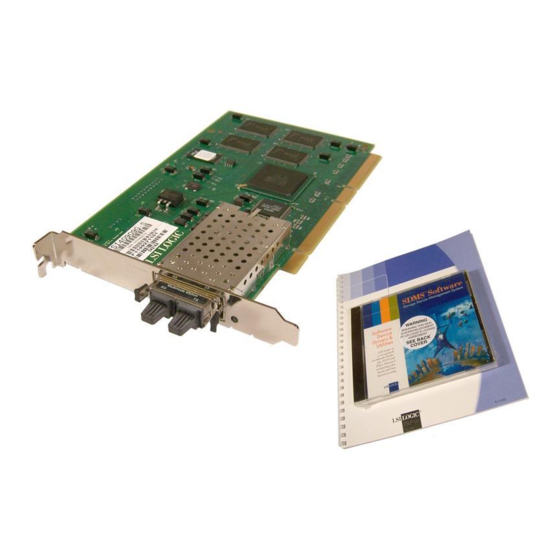
- Page 1 USER’S GUIDE LSI40909G-S PCI to Fibre Channel Host Adapter for Sun Solaris Version 1.0 F e b r u a r y 2 0 0 1 ® S14062...
-
Page 2: Electromagnetic Compatibility Notices
Consult the dealer or an experienced radio/TV technician for help. Shielded cables for SCSI connection external to the cabinet are used in the compliance testing of this Product. LSI Logic is not responsible for any radio or television interference caused by unauthorized modification of this equipment or the substitution or attachment of connecting cables and equipment other than those specified by LSI Logic. - Page 3 LSI Logic; nor does the purchase or use of a product from LSI Logic convey a license under any patent rights, copyrights, trademark rights, or any other of the intellectual property rights of LSI Logic or third parties.
- Page 5 Preface This book is the primary reference and user’s guide for the LSI Logic LSI40909G-S PCI to Fibre Channel Host Adapter for Sun Solaris board. It contains a complete functional description for the LSI40909G-S as well as complete physical and electrical specifications.
- Page 6 Related Publications LSIFC909 Fibre Channel I/O Processor Technical Manual, Order Number S14029.A Revision Record Revision Date Remarks 02/01 First printing. Preface...
-
Page 7: Table Of Contents
Contents Chapter 1 LSI40909G-S Description General Description Features 1.2.1 1.2.2 1.2.3 1.2.4 Chapter 2 Installing the LSI40909G-S Quick Installation Procedure Detailed Installation Procedure 2.2.1 2.2.2 Chapter 3 Software Installation Installing the Sun SPARC Solaris Fusion-MPT™ Drivers 3.1.1 3.1.2 3.1.3 3.1.4 3.1.5... - Page 8 Thermal, Atmospheric Characteristics Electromagnetic Compliance Safety Characteristics The PCI Interface The FC Interface The FC Link Activity/Link Fault LED Hardware Connections for the LSI40909G-S Inserting the Host Adapter System Devices Listing FC Disk Devices Listing Persistent Device Mapping Clearing an Entry...
-
Page 9: Chapter 1 Lsi40909G-S Description
Section 1.2, “Features,” page 1-1 1.1 General Description The LSI Logic LSI40909G-S provides an FC interface to Sun Solaris PCI computer systems. This board is referred to as the LSI40909G-S throughout this guide. The LSI40909G-S uses the LSIFC909 FC I/O Processor chip. -
Page 10: Fc Interface
Serial EEPROM configuration storage Card edge keyed as a universal add-in card 1.2.2 FC Interface The LSIFC909 contains the FC functionality for the LSI40909G-S. The LSIFC909 generates signal timing and link protocol in compliance with FC standards. The FC interface includes these features:... -
Page 11: Fc Link Activity/Link Fault Led
1.2.4 FC Link Activity/Link Fault LED The LSI40909G-S provides a dual-purpose LED visible through the bracket which indicates activity on the FC link when the LED is green. This LED turns yellow when there has been a fault on the FC link. - Page 12 3.75 pc 10.25 pc 11.25 pc 38.25 pc 34.5 pc 4.333 pc 44.25 pc 48.583 p LSI40909G-S Description 52.5 pc...
-
Page 13: Chapter 2 Installing The Lsi40909G-S
Step 1. Ground yourself before removing this host adapter board. Step 2. Remove the LSI40909G-S from the packing and check that it is Step 3. Open your PC cabinet and select an appropriate open PCI slot. -
Page 14: Detailed Installation Procedure
Perform the following steps to install the LSI40909G-S. Step 1. Ground yourself before removing this host adapter board. Step 2. Remove the LSI40909G-S from the packing and check that it is Step 3. Switch off the computer and unplug power cords for all Step 4. - Page 15 J1 connector opposite the bracket remains uninserted. See Figure Note: For the LSI40909G-S to function as a 64-bit device, it must be inserted in a 64-bit PCI slot. If the LSI40909G-S is inserted in a 32-bit PCI slot, it will function as a 32-bit device.
-
Page 16: Hardware Connections For The Lsi40909G-S
Link Fault LED Step 7. Carefully insert edge connector J1 (see Installing the LSI40909G-S 34.5 pc Hardware Connections for the LSI40909G-S GBIC adapter into the PCI slot. Make sure the edge connector is properly aligned before pressing the board into place as shown in bracket around connector J2 should fit where you removed the... -
Page 17: Inserting The Host Adapter
Inserting the Host Adapter Bracket Screw Step 8. Secure the board with the bracket screw (see making the external FC link connection. Step 9. Connect the FC cable to the LSI40909G-S. Detailed Installation Procedure 4.333 pc 32-bit PCI Slots 64-bit PCI Slots Figure 2.2) before... - Page 18 3.75 pc 10.25 pc 11.25 pc 38.25 pc 34.5 pc 4.333 pc 44.25 pc 48.583 p Installing the LSI40909G-S 52.5 pc...
-
Page 19: Chapter 3 Software Installation
CPU overhead and high I/O throughput, making use of the LSI Logic Fusion-MPT architecture. The LSI Logic FC adapters have built-in Fcode, designed to operate in the Sun OpenBoot environment, allowing FC devices to be available to the OpenBoot (ok) prompt. -
Page 20: Features
Operating system Network Boot Server Firmware 1. Only required if you will be using the LSI Logic module to support your System disk. After installing the module in an appropriate PCI slot and making all the necessary internal and external connections to the module, power on the host system. -
Page 21: System Devices Listing
Note: /pci@1f,0/pci@1/pci@2/IntraServer,fc@4 identifies the first FC interface on an LSI Logic/IntraServer 7000 Series adapter. The above is an example. The output of show-devs may vary depending on your system and configuration. Use the corresponding entries on your system, not those given here. -
Page 22: Identifying The Fc Disks
3.1.4 Identifying the FC Disks The probe-scsi-all command is used to identify the FC disk devices on your LSI Logic/IntraServer adapter, as shown in Figure 3.2 ok probe-scsi-all /pci@1f,0/pci@1/IntraServer,Ultra2-scsi@1 Target 0 Unit 0 /pci@1f,0/pci@1/pci@2/IntraServer,fc@7 MPT Firmware Version 1.00 Target 0... -
Page 23: Persistent Device Naming
If the FC disks on your LSI Logic/IntraServer adapter are not identified by your system, check the following: 1. Are all the FC cables correctly connected to the disk enclosure? 2. Is the disk enclosure powered up? 3. If the external disk enclosure required a loopback connector, is the loopback connector correctly installed? 3.1.5 Persistent Device Naming... -
Page 24: Persistent Device Mapping
Figure 3.3 ok show-disks a) /pci@1f,0/pci@1/IntraServer,fc@2/disk b) /pci@1f,0/pci@1/IntraServer,Ultra2-scsi@1/disk c) /pci@1f,0/pci@1,1/ide@3/cdrom d) /pci@1f,0/pci@1,1/ide@3/disk e) /pci@1f,0/pci@1,1/ebus@1/fdthree@14,3203f0 q) NO SELECTION Enter Selection, q to quit: a /pci@1f,0/pci@1/IntraServer,fc@2/disk has been selected. Type ^Y (Control-Y) to insert it in the command line. e.g. ok nvalias mydev ^Y for creating devalias mydev for /pci@1f,0/pci@1/IntraServer,fc@2/disk ok select/pci@1f,0/pci@1/IntraServer,fc@2 ok show-children... -
Page 25: Itmpt Device Driver
The following sections describe the procedures to install the driver on Solaris. 3.2 Installing the itmpt Sun SPARC Solaris FC Driver The LSI Logic LSI40909G-S uses the itmpt FC driver for Solaris. This driver is included with your adapter kit. Note: 3.2.1 Existing System Installation... - Page 26 3.2.1.1 Floppy Disk Install If you received the drivers on a floppy diskette, follow these steps: Step 1. Place the diskette in the floppy drive and execute the volcheck Step 2. Change the directory to the root of the floppy Step 3.
-
Page 27: Pkgadd Procedure
Processing package instance <ITImpt> from </floppy/intraserver> LSI Logic/IntraServer FusionMPT(tm) Fibrechannel/SCSI drivers (sparc) itmpt kit version 1.1 IntraServer Technology, Inc / LSI Logic Using </> as the package base directory. ## Processing package information. ## Processing system information. 2 package pathnames are already properly installed. -
Page 28: Completing Floppy Disk Installation
Following installation, please reboot the system to properly configure and load the drivers. Installation of <ITImpt> was successful. To support nonzero LUNs, which is default for most RAID controllers such as the LSI Logic MetaStor /kernel/drv/ssd.conf as shown in 3-10 Software Installation Completing Floppy Disk Installation for additional information. -
Page 29: Kernel/Drv/Ssd.conf
Figure 3.8 Example: With just the default entry for each target in /kernel/drv/ssd.conf, only devices at LUN 0 will be probed. name="ssd" parent="itmpt" target=0; To add nonzero LUN support, replace the above entry with an entry for each LUN to probe, such as: name="ssd"... -
Page 30: Network Installation Procedure
3.2.2 Network Installation Procedure If you are using your LSI Logic/IntraServer adapter to support your Sparc Solaris system disk, you must install the Solaris operating system using a network install. This section describes a complete installation of Solaris to a client system using LSI Logic/IntraServer FC adapters for the system disk. - Page 31 The message “major number maximum based on server, not client” can safely be ignored. Running the install.sh script this way copies and installs the LSI Logic/IntraServer drivers into the Tools/Boot/ area of the boot files and allows LSI Logic/IntraServer adapters to be booted for installation using the bootserver.
- Page 32 It is important to choose "Manual Reboot" rather than "Auto Reboot" during the installation of Solaris on the target machine. If you choose "Auto Reboot", you will not have the opportunity to complete the installation of the LSI Logic/IntraServer FC drivers and your system will fail to boot. /sbin/itmptinst...
-
Page 33: Troubleshooting
Your Sun machine will prompt you to allow power saving automatic shutdown. You must answer no to this question if you are using the LSI Logic/IntraServer adapter to support your boot disk. If you change the disk drive configuration of your machine,... - Page 34 This is a fatal error that is not recoverable. Please report this error to technical support. The adapter is not a valid LSI Logic/IntraServer adapter licensed for use with Solaris. The adapter is in a slot that cannot be used with this driver.
- Page 35 Table 3.2 Error Messages (Cont.) Error Messages itmpt<n>: The adapter is malfunctioning or is of an unknown type. itmpt<n>: The adapter is malfunctioning. itmpt<n>: Failed to create minor node required for DMI interface. itmpt<n>: Could not attach to the SCSI subsystem. itmpt<n>: Failed to allocate memory.
- Page 36 3-18 Software Installation...
-
Page 37: Chapter 4 Lsi40909G-S Technical Characteristics
FCC. 4.1.1 Physical Characteristics The LSI40909G-S is a PCI short card; the dimensions are 168 x 98 mm (6.625 x 3.875 inches). J1 is the PCI edge connector. The external FC connection is made through a 1 Gigabit/s GBIC optical module. -
Page 38: Electrical Characteristics
123456 GBIC 4.1.2 Electrical Characteristics Under normal conditions, the LSI40909G-S maximum power requirement is: + 5 V DC, Under abnormal conditions + 5 V current may be higher. The PCI PRSNT1/ and PRSNT2/ pins are set to indicate a 7.5 W maximum configuration. -
Page 39: Electromagnetic Compliance
4.2 Operational Environment Use the LSI40909G-S in PCI computer systems with an ISA/EISA bracket type. The LSI Logic supplied FC BIOS and firmware operate the boards. An on-board flash memory device and a serial EEPROM are provided to allow BIOS code and open boot code support through PCI. -
Page 40: The Fc Interface
This LED turns yellow when there has been a fault on the FC link. 4.3 IEEE Unique Address Each LSI40909G-S is provided with a unique IEEE address. The last six hexadecimal characters of this address appear on a label on the board. -
Page 41: Appendix A Glossary Of Terms And Abbreviations
A unit of information consisting of eight bits. Channel A point-to-point link, the main task of which is to transport data from one point to another. LSI40909G-S PCI to Fibre Channel Host Adapter for Sun Solaris 34.5 pc 4.333 pc 12 pc 12.938 p... - Page 42 Configuration Refers to the way a computer is setup; the combined hardware components (computer, monitor, keyboard, and peripheral devices) that make up a computer system; or the software settings that allow the hardware components to communicate with each other. Central Processing Unit. The “brain” of the computer that performs the actual computations.
- Page 43 FC-1 Middle level of the FC-PH standard, defining the 8B/10B encoding/decoding and transmission protocol. FC-2 Highest level of FC-PH, defining the rules for signaling protocol and describing transfer of the frame, sequence, and exchanges. FC-3 The hierarchical level in the FC standard that provides common services, such as striping definition.
- Page 44 Host The computer system in which a SCSI host adapter is installed. It uses the SCSI host adapter to transfer information to and from devices attached to the SCSI bus. Host Adapter A circuit board or integrated circuit that provides a SCSI bus connection to the computer system.
- Page 45 Operating A program that organizes the internal activities of the computer and its System peripheral devices. An operating system performs basic tasks such as moving data to and from devices, and managing information in memory. It also provides the user interface. Operation A term, defined in FC-2, that refers to one of the FC “building blocks”...
- Page 46 Responder An FC term referring to the answering device. RISC Core LSIFC909 chips contain a RISC (Reduced Instruction Set Computer) processor, programmed through microcode scripts. Read Only Memory. Memory from which information can be read but not changed. The contents of ROM are not erased when the computer is turned off.
- Page 47 System BIOS Controls the low level POST (Power-On Self-Test), and basic operation of the CPU and computer system. Target ID. Topology The logical and/or physical arrangement of stations on a network. Upper Layer Protocol. VCCI Voluntary Control Council for Interference. Virtual Memory Space on a hard disk that can be used as if it were RAM.
- Page 48 3.75 pc 10.25 pc 11.25 pc 38.25 pc 34.5 pc 4.333 pc 44.25 pc 48.583 p Glossary of Terms and Abbreviations 52.5 pc...
-
Page 49: Customer Feedback
Please include your name, phone number, fax number, and company address so that we may contact you directly for clarification or additional information. Thank you for your help in improving the quality of our documents. LSI40909G-S PCI to Fibre Channel Host Adapter for Sun Solaris... - Page 50 Reader’s Comments Fax your comments to: Please tell us how you rate this document: LSI40909G-S PCI to Fibre Channel Host Adapter for Sun Solaris User’s Guide. Place a check mark in the appropriate blank for each category. Completeness of information Clarity of information Ease of finding information...
- Page 51 U.S. Distributors by State California A. E. Avnet Electronics Agoura Hills http://www.hh.avnet.com B. M. B. M. Bell Microproducts, Granite Bay Inc. (for HAB’s) B. M. http://www.bellmicro.com Irvine I. E. Insight Electronics A. E. http://www.insight-electronics.com B. M. W. E. Wyle Electronics I.
- Page 52 U.S. Distributors by State (Continued) Montana Ohio A. E. Tel: 800.526.1741 Cleveland W. E. Tel: 801.974.9953 A. E. W. E. Nebraska Dayton A. E. Tel: 800.332.4375 A. E. W. E. Tel: 303.457.9953 I. E. W. E. Nevada Strongsville Las Vegas B.
- Page 53 Direct Sales Representatives by State (Components and Boards) E. A. Earle Associates Texas E. L. Electrodyne - UT Austin Group 2000 I. S. Infinity Sales, Inc. Arlington ION Associates, Inc. R. A. Rathsburg Associ- Houston ates, Inc. Synergy Associates, Utah Inc.
- Page 54 Sales Offices and Design Resource Centers LSI Logic Corporation Fort Collins Corporate Headquarters 2001 Danfield Court Fort Collins, CO 80525 1551 McCarthy Blvd Tel: 970.223.5100 Milpitas CA 95035 Tel: 408.433.8000 Fax: 970.206.5549 Fax: 408.433.8989 Florida NORTH AMERICA Boca Raton 2255 Glades Road...
- Page 55 Sales Offices and Design Resource Centers (Continued) Korea Seoul LSI Logic Corporation of Korea Ltd 10th Fl., Haesung 1 Bldg. 942, Daechi-dong, Kangnam-ku, Seoul, 135-283 Tel: 82.2.528.3400 Fax: 82.2.528.2250 The Netherlands Eindhoven LSI Logic Europe Ltd World Trade Center Eindhoven Building ‘Rijder’...
-
Page 56: International Distributors
12 Interface Business Park Bincknoll Lane Fax: 31.40.2.510255 Wootton Bassett, Swindon, Wiltshire SN4 8SY Switzerland Tel: 44.1793.849933 Brugg Fax: 44.1793.859555 LSI Logic Sulzer AG Mattenstrasse 6a CH 2555 Brugg Sales Offices with Tel: 41.32.3743232 Design Resource Centers Fax: 41.32.3743233 Taiwan Taipei...
Need help?
Do you have a question about the LSI40909G-S and is the answer not in the manual?
Questions and answers