
Related Manuals for LSI LSI7102XP-LC


Summary of Contents for LSI LSI7102XP-LC
- Page 1 USER’S GUIDE 2 Gbit/s Fibre Channel Host Adapters LSI7102XP-LC, LSI7102LXP-LC LSI7202XP-LC, LSI7202LXP-LC LSI7402XP-LC LSI7202EP-LC, LSI7202EP LSI7402EP-LC, LSI7402EP A u g u s t 2 0 0 5 Version 2.1 ® DB15-000264-02...
- Page 2 LSI Logic; nor does the purchase or use of a product from LSI Logic convey a license under any patent rights, copyrights, trademark rights, or any other of the intellectual property rights of LSI Logic or third parties.
- Page 3 Preface This book is the primary reference and user’s guide for the LSI Logic family of 2 Gbit/s Fibre Channel host adapter boards. It contains a complete functional description of these boards as well as complete physical and electrical specifications. LSI Logic uses Class 1 transceivers on the host adapter boards contained in this user’s guide.
- Page 4 PCI Express Base Specification, Rev. 1.0a Revision Record Revision Date Remarks 10/02 Preliminary release 04/03 Final release 08/05 Updated to add the LSI7102LXP-LC, LSI7202LXP-LC, LSI7202EP, LSI7202EP-LC, LSI7402EP, and LSI7402EP-LC. Preface Copyright © 2002, 2005 by LSI Logic Corporation. All rights reserved.
-
Page 5: Table Of Contents
PCI System ID Values PCI Subsystem ID Values Unique World Wide Name 2 Gbit/s Fibre Channel Host Adapters User’s Guide Copyright © 2002 - 2005 by LSI Logic Corporation. All rights reserved. Before You Start Installing the Host Adapter PCI-X Interface... - Page 6 Advanced User: Adjusting Default Firmware Settings 3.4.1 3.4.2 Troubleshooting Contents Copyright © 2002 - 2005 by LSI Logic Corporation. All rights reserved. LSI7102XP-LC Host Adapter Configuration LSI7102XP-LC Connector and Indicator LED LSI7102LXP-LC Host Adapter Configuration LSI7102LXP-LC Connector and Indicator LED LSI7202XP-LC Host Adapter Configuration...
- Page 7 4.7.5 4.7.6 4.7.7 4.7.8 Customer Feedback Contents Copyright © 2002 - 2005 by LSI Logic Corporation. All rights reserved. LSI Logic Boot BIOS Features BIOS Overview LSI Logic BIOS Boot Specification (BBS) Adapter Properties Menu Persistent ID Menu Device Properties Menu...
- Page 8 Contents Copyright © 2002 - 2005 by LSI Logic Corporation. All rights reserved.
- Page 9 Interrupt Coalescing Values Select Controller Select Device Inserting Disk Name in Command Line Setting Device 0 as Persistent Clearing Persistent Device Map Copyright © 2002 - 2005 by LSI Logic Corporation. All rights reserved. 2-10 2-11 2-12 2-13 2-14 2-15...
- Page 10 Copyright © 2002 - 2005 by LSI Logic Corporation. All rights reserved.
- Page 11 LSI7202EP Link Activity/Link Fault LEDs 2.13 LSI7402XP-LC Link Activity/Link Fault LEDs 2.14 LSI7402EP-LC Link Activity/Link Fault LEDs 2.15 LSI7402EP Link Activity/Link Fault LEDs Copyright © 2002 - 2005 by LSI Logic Corporation. All rights reserved. 2-11 2-13 2-15 2-17 2-19 2-21...
- Page 12 Copyright © 2002 - 2005 by LSI Logic Corporation. All rights reserved.
-
Page 13: Quick Installation Procedure
Channel Fibre Channel I/O Processor Technical Manual and LSIFC919X Single Channel Fibre Channel I/O Processor Technical Manual. 2 Gbit/s Fibre Channel Host Adapters User’s Guide Copyright © 2002 - 2005 by LSI Logic Corporation. All rights reserved. Host Adapter LSI7102XP-LC, LSI7102LXP-LC... -
Page 14: Quick Installation Procedure
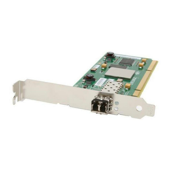
Step 5. Make any configuration changes. Step 6. Close your PC cabinet cover. Step 7. Connect the FC cable to the host adapter. Installation Procedures Copyright © 2002 - 2005 by LSI Logic Corporation. All rights reserved. is not damaged. Figure 1.1 page 1-4 illustrates an example of this host adapter board. -
Page 15: Detailed Installation Procedure
Step 3. Switch off the computer and unplug the power cords for all Step 4. Remove the cover from your computer according to the Caution: Detailed Installation Procedure Copyright © 2002 - 2005 by LSI Logic Corporation. All rights reserved. Section 1.3.2, “Installing the Host Adapter,” is not damaged. Figure 1.1 illustrates an example of this host adapter board. - Page 16 Link Activity/ Link Fault LED Transceiver Installation Procedures Copyright © 2002 - 2005 by LSI Logic Corporation. All rights reserved. connector contacts. LSI Logic recommends using a static ground strap. Refer to the user’s manual supplied with your computer to confirm the location of the PCI slots.
- Page 17 Inserting the LSI Logic Host Adapter Bracket Screw Step 8. Secure the board with the bracket screw (see make the external FC link connection. Detailed Installation Procedure Copyright © 2002 - 2005 by LSI Logic Corporation. All rights reserved. Figure 1.1) of Figure 1.2. The...
- Page 18 Installation Procedures Copyright © 2002 - 2005 by LSI Logic Corporation. All rights reserved.
-
Page 19: Gbit/S Fc
Section 2.7, “Unique World Wide Name” Section 2.8, “Physical Characteristics” General Description The LSI Logic 2 Gbit/s family of FC host adapters makes use of state-of- the-art, 2 Gbit/s FC technology to provide the highest possible performance and most flexible storage configuration available. These LSI Logic host adapters support 1 Gbit/s or 2 Gbit/s FC speeds, and detect and correctly set the speed of operation automatically. -
Page 20: Lsi Logic 2 Gbit/S Fc Host Adapter Descriptions
LSI7402XP-LC LSI7402EP-LC LSI7402EP Hardware and Software Support – The LSI Logic 2 Gbit/s family of FC host adapter supports most major software operating systems, such as Sun Solaris (2.6 and greater), Windows Server (NT 4.0, 2000, XP, 2003), Linux (RedHat, Suse, Caldera, Turbo), NetWare, and UnixWare. These host adapters use the Fusion-MPT architecture for all major operating systems. -
Page 21: Features
Serial EEPROM configuration storage Host adapters comply with PCI-X/133 Local Bus Specification, Rev. 1.0a Features Copyright © 2002 - 2005 by LSI Logic Corporation. All rights reserved. Hardware and Software Requirements Requirements Any Sun Microsystems computer with a 3.3 V PCI slot Solaris 8 operating environment OpenBoot PROM, version 2.1 or greater... -
Page 22: Pci Express Interface
2.2.3 FC Interface The LSIFC929X and LSIFC919X processors contain the FC functionality for all the LSI Logic 2 Gbit/s FC host adapters. The LSIFC929X and LSIFC919X processors generate signal timing and link protocol in compliance with FC standards. The FC interface includes these features:... -
Page 23: Electrical Characteristics
Storage Temperature: 45 C to +85 C (dry bulb) Relative Humidity Range: 0% to 95%, noncondensing Physical Environment Copyright © 2002 - 2005 by LSI Logic Corporation. All rights reserved. lists the maximum power requirements and includes all of the Maximum Power Requirements PCI +3.3 V... -
Page 24: Electromagnetic Compliance
PCI bus slot, all voltages are below the SELV 42.4 V limit. Operational Environment Use the LSI Logic 2 Gbit/s family of FC host adapters in PCI-X or PCI Express computer systems with an Industry Standard Architecture/Extended Industry Standard Architecture (ISA/EISA) bracket type. -
Page 25: Fc Interface
ID (DID) values to allow drivers and BIOS to recognize them as 2 Gbit/s capable FC products. provides the VID and DID for all LSI Logic 2 Gbit/s FC host adapters. PCI System ID Values Copyright ©... -
Page 26: Pci Subsystem Id Values
LSI7402EP PCI Subsystem ID Values All LSI Logic 2 Gbit/s host adapters are assigned PCI Subsystem Vendor IDs (SVIDs) and Subsystem IDs (SSIDs) to allow drivers and BIOS to differentiate the individual host adapter variants. The SVID and SSID are listed below. -
Page 27: Unique World Wide Name
EEPROM. Physical Characteristics The LSI Logic 2 Gbit/s family of FC host adapters includes one to four external FC connectors, depending on the host adapter you have chosen. The host adapters are all available with optical or copper interconnects. -
Page 28: Lsi7102Xp-Lc Connector And Indicator Led
LC connector provides the connection from the adapter channel to the FC subsystem. The indicator LED indicates link status, activity, and link fault. 2-10 2 Gbit/s FC Host Adapter Characteristics Copyright © 2002 - 2005 by LSI Logic Corporation. All rights reserved. LSI7102XP-LC Host Adapter Configuration LSI7102XP-LC LSIFC919X Osc. -
Page 29: Lsi7102Xp-Lc Connector And Indicator Led
Table 2.7 LSI7102XP-LC Link Activity/Link Fault LEDs LED Appearance Physical Characteristics Copyright © 2002 - 2005 by LSI Logic Corporation. All rights reserved. Link Activity Green Blinking Fault Yellow... -
Page 30: Lsi7102Lxp-Lc Host Adapter Configuration
2.8.3 LSI7102LXP-LC Host Adapter Configuration The LSI Logic LSI7102LXP-LC is a single channel 2 Gbit/s FC adapter. One LC optical connector is used for I/O, which is accessible through the module bracket. The LSI7102LXP-LC host adapter uses the LSIFC919X processor, providing one Fusion-MPT channel. -
Page 31: Lsi7102Lxp-Lc Connector And Indicator Led
Table 2.8 LED Appearance Physical Characteristics Copyright © 2002 - 2005 by LSI Logic Corporation. All rights reserved. LSI7102LXP-LC Connector and Indicator LED Port 0 Port 0 LED describes the LSI7102LXP-LC Link Activity/Link Fault LED... -
Page 32: Lsi7202Xp-Lc Host Adapter Configuration
PCI-X/133 Specification, Revision 1.0a. major components on the LSI7202XP-LC. Figure 2.5 2-14 2 Gbit/s FC Host Adapter Characteristics Copyright © 2002 - 2005 by LSI Logic Corporation. All rights reserved. LSI7202XP-LC Host Adapter Configuration LSI7202XP-LC Port 1, SFP LSIFC929X Osc. -
Page 33: Lsi7202Xp-Lc Connectors And Indicator Leds
Table 2.9 LED Appearance Physical Characteristics Copyright © 2002 - 2005 by LSI Logic Corporation. All rights reserved. LSI7202XP-LC Connectors and Indicator LEDs Port 1 LED Port 1 Port 0... -
Page 34: Lsi7202Lxp-Lc Host Adapter Configuration
PCI-X/133 Specification, Revision 1.0a. major components on the LSI7202LXP-LC. Figure 2.7 2-16 2 Gbit/s FC Host Adapter Characteristics Copyright © 2002 - 2005 by LSI Logic Corporation. All rights reserved. LSI7202LXP-LC Host Adapter Configuration LSI7202XP-LC Port 1, SFP LSIFC929X Osc. -
Page 35: Lsi7202Lxp-Lc Connectors And Indicator Leds
Table 2.10 LED Appearance Physical Characteristics Copyright © 2002 - 2005 by LSI Logic Corporation. All rights reserved. LSI7202LXP-LC Connectors and Indicator LEDs Port 1 LED Port 1 Port 0... -
Page 36: Lsi7202Ep-Lc Host Adapter Configuration
PCI Express Specification, Revision 1.0a. major components on the LSI7202EP-LC. Figure 2.9 2-18 2 Gbit/s FC Host Adapter Characteristics Copyright © 2002 - 2005 by LSI Logic Corporation. All rights reserved. LSI7202EP-LC Host Adapter Configuration LSI7202EP-LC LSIFC929X Port 1, SFP Osc. -
Page 37: 2.8.10 Lsi7202Ep-Lc Connectors And Indicator Leds
Table 2.11 LED Appearance Physical Characteristics Copyright © 2002 - 2005 by LSI Logic Corporation. All rights reserved. Port 1 LED Port 1 Port 0 Port 0 LED... -
Page 38: 2.8.11 Lsi7202Ep Host Adapter Configuration
2.8.11 LSI7202EP Host Adapter Configuration The LSI Logic LSI7202EP is a dual-channel, 2 Gbit/s FC adapter. Two connectors, used for I/O, are accessible through the module bracket. The LSI7202EP uses the LSIFC929X, providing two Fusion-MPT channels. The LSI7202EP is a PCI short card; the dimensions are 6.875 inches x 4.2 inches. -
Page 39: 2.8.12 Lsi7202Ep Connectors And Indicator Leds
Table 2.12 LED Appearance Physical Characteristics Copyright © 2002 - 2005 by LSI Logic Corporation. All rights reserved. Port 1 LED Port 1 Port 0 Port 0 LED... -
Page 40: 2.8.13 Lsi7402Xp-Lc Host Adapter Configuration
PCI-X/133 Specification, Revision 1.0a. major components on the LSI7402XP-LC. Figure 2.13 LSI7402XP-LC Host Adapter Configuration 2-22 2 Gbit/s FC Host Adapter Characteristics Copyright © 2002 - 2005 by LSI Logic Corporation. All rights reserved. LSI7402XP-LC LSIFC929X Port 3, SFP Port 2, SFP Port 1, SFP Osc. -
Page 41: 2.8.14 Lsi7402Xp-Lc Connectors And Indicator Leds
Table 2.13 LED Appearance Physical Characteristics Copyright © 2002 - 2005 by LSI Logic Corporation. All rights reserved. Port 3 Port 2 Port 1 Port 0... -
Page 42: 2.8.15 Lsi7402Ep-Lc Host Adapter Configuration
PCI Express Specification, Revision 1.0a. major components on the LSI7402EP-LC. Figure 2.15 LSI7402EP-LC Host Adapter Configuration 2-24 2 Gbit/s FC Host Adapter Characteristics Copyright © 2002 - 2005 by LSI Logic Corporation. All rights reserved. LSI7402EP LSIFC929X Port 3, SFP Port 2, SFP Port 1, SFP Osc. -
Page 43: 2.8.16 Lsi7402Ep-Lc Connectors And Indicator Leds
Table 2.14 LED Appearance Physical Characteristics Copyright © 2002 - 2005 by LSI Logic Corporation. All rights reserved. Port 3 Port 2 Port 1 Port 0... -
Page 44: 2.8.17 Lsi7402Ep Host Adapter Configuration
2.8.17 LSI7402EP Host Adapter Configuration The LSI Logic LSI7402EP is a quad-channel, 2 Gbit/s FC adapter. Four connectors, used for I/O, are accessible through the module bracket. The LSI7402EP uses two LSIFC929X devices, providing four Fusion-MPT channels. The LSI7402EP is a PCI short card; the dimensions are 6.875 inches x 4.2 inches. -
Page 45: 2.8.18 Lsi7402Ep Connectors And Indicator Leds
Table 2.15 LED Appearance Physical Characteristics Copyright © 2002 - 2005 by LSI Logic Corporation. All rights reserved. Port 3 Port 2 Port 1 Port 0... - Page 46 2-28 2 Gbit/s FC Host Adapter Characteristics Copyright © 2002 - 2005 by LSI Logic Corporation. All rights reserved.
-
Page 47: Gbit/S Fibre Channel Host Adapters User's Guide
Section 3.4, “Advanced User: Adjusting Default Firmware Settings” Section 3.5, “Troubleshooting” The LSI Logic FC chips and host adapters contain firmware that presents a multiprotocol service layer based on the Fusion-MPT architecture. The FC firmware provides FCP (SCSI-3 over FC) Initiator, FCP Target, and LAN interface services to the host system. -
Page 48: Fc Firmware
Fusion-MPT services provided by the LSI Logic FC firmware. The host driver is responsible for initializing the controller, building request message frames, issuing request message Firmware Installation Procedure Copyright ©... -
Page 49: Download New Fc Firmware
FC-unique exceptions. With the Fusion-MPT architecture, parallel SCSI host drivers can be used with the LSI Logic FC controllers with little or no additional functionality for FC. Download New FC Firmware To begin, you must first download new host adapter firmware component(s) from the LSI Logic web site (www.lsilogic.com). -
Page 50: Update The Fc Firmware
These files represent updated code that you may store on your LSI Logic host adapter using one of the methods described in the next sections. Update the FC Firmware The process of updating the FC firmware varies slightly, depending on the operating system. - Page 51 Select a device: [1-2 or 0 to quit] Step 5. From the subsequent displayed list, select option menu 2 or 4 as shown (Figure Update the FC Firmware Copyright © 2002 - 2005 by LSI Logic Corporation. All rights reserved. (Figure 3.1). MPT Rev Firmware Rev...
- Page 52 Step 8. Reset the adapter using option 99, or reboot to begin running Step 9. Enter 0 to quit the program. Firmware Installation Procedure Copyright © 2002 - 2005 by LSI Logic Corporation. All rights reserved. LSIUtil Download Options LSIUtil File Download the new firmware.
-
Page 53: Command Line Update Tool For Dos
Note: Running the MPTUtil Program – update the LSI Logic FC firmware on any 4 Gbit/s host adapter. Locate MPTUtil distribution media, as well as the DOS4GW.exe file. Copy these files to a blank, formatted diskette. Label it “FC Firmware diskette.”... -
Page 54: Advanced User: Adjusting Default Firmware Settings
LSI Logic during the original manufacturing process. Adjustments to these parameters will affect future behavior of the Firmware Installation Procedure Copyright © 2002 - 2005 by LSI Logic Corporation. All rights reserved. To update the firmware, select option a - Update Firmware. MPTUtil Options... -
Page 55: Adjusting Link Speed
3.4.1 Adjusting Link Speed The link speed of the LSI Logic host adapters is configurable. By default, the link speed is set to Auto. This means the host adapter automatically detects the link speed of all other nodes on the link and automatically adjusts itself to work with those nodes. -
Page 56: Adjusting Interrupt Coalescing
Step 3. Exit the FCUtil utility using the menu option q - Quit. 3.4.2 Adjusting Interrupt Coalescing The LSI Logic host adapters can complete multiple I/O requests per host interrupt. Interrupt coalescing is used to reduce CPU interrupts by pooling multiple disk command completions (I/O) into one interrupt. This feature may be enabled or disabled. -
Page 57: Interrupt Coalescing Values
Coalescing Timeout – This is failsafe time period that specifies the maximum amount of time (in milliseconds) to interrupt regardless of Coalescing depth. Advanced User: Adjusting Default Firmware Settings Copyright © 2002 - 2005 by LSI Logic Corporation. All rights reserved. 3-11... -
Page 58: Troubleshooting
Host Adapter boards. When these errors occur, the LED flashes a four-digit sequence, which is the error code. These types of errors should be reported to LSI Logic Technical Support. The technical support representative will ask for additional system configuration information, including the type of system used, the FC configuration and type of peripherals (including version... -
Page 59: Bios Features
LSI Logic FC boot BIOS for Intel/AMD-based platforms, and LSI Logic FC OpenBoot BIOS for Solaris SPARC platforms. Both the LSI Logic boot BIOS and OpenBoot BIOS are stored on the FC host adapter boards. 2 Gbit/s Fibre Channel Host Adapters User’s Guide... -
Page 60: Lsi Logic Boot Bios
Use that menu to select the device and rearrange the order. Then exit to continue the boot process. BIOS Features Copyright © 2002 - 2005 by LSI Logic Corporation. All rights reserved. The Boot feature is disabled by default on all host adapters shipped from LSI Logic. -
Page 61: Starting The Lsi Logic Boot Bios Configuration Utility
Main Menu When you invoke the LSI Logic boot BIOS CU, the Main menu appears. This screen displays a scrolling list of up to 256 host adapters in the system and information about each of them. -
Page 62: Adapter Properties Menu
ID screens through the F2 key, which moves the screen forward or back by 16 entries. However, the CU requires storing any modifications to the BIOS Features Copyright © 2002 - 2005 by LSI Logic Corporation. All rights reserved. for details. for details. -
Page 63: Device Properties Menu
The Boot Adapter List menu specifies the order in which adapters boot when more than one LSI Logic host adapter is in a system. Up to four adapters in a system can be selected as bootable. Only one of the four bootable adapters can control a boot volume. -
Page 64: Global Properties Menu
Exiting the LSI Logic Boot BIOS Configuration Utility The Exit menu for the LSI Logic boot BIOS configuration utility is used for all six of the menus listed in However, the available functionality is different for the Main menu and the five subordinate menus. -
Page 65: Openboot Bios
Solaris SPARC 2.6, Solaris SPARC 2.7, and Solaris 8 Open Firmware environments Root Boot device selection from any target device Standard command line interface, with help query Configuration options and selection capability for each host adapter OpenBoot BIOS Copyright © 2002 - 2005 by LSI Logic Corporation. All rights reserved. -
Page 66: Identifying The Fc Devices
Unit 0 Disk WWN 2100002037105212 Port ID 1 Target 3 Unit 0 Disk WWN 2100002037103da8 Port ID 26 BIOS Features Copyright © 2002 - 2005 by LSI Logic Corporation. All rights reserved. DDRS-34560D DC1B SEAGATE ST39173FC 6615 SEAGATE ST39173FC 6258... -
Page 67: Verifying Installation
Step 2. When the banner is displayed, press the STOP+A keys to Step 3. Use the show-devs command to list the system devices. You OpenBoot BIOS Copyright © 2002 - 2005 by LSI Logic Corporation. All rights reserved. SEAGATE ST39173FC interrupt the boot process and stop at the ok prompt. -
Page 68: Adapter-Specific Settings
Selecting a port or adapter brings the port online and allows you to show or set certain adapter specific parameters. 4-10 BIOS Features Copyright © 2002 - 2005 by LSI Logic Corporation. All rights reserved. /upa@8,480000/SUNW,ffb@0,0 /pci@8,700000/IntraServer,fc@2 /pci@8,700000/IntraServer,fc@1,1... - Page 69 000013e9 revision-id device-id vendor-id OpenBoot BIOS Copyright © 2002 - 2005 by LSI Logic Corporation. All rights reserved. 1.02.00 1.00 83001014 00000000 001a0000 00000000 00020000 8300101c 00000000 00190000 00000000 00010000 82001030 00000000 02000000 00000000 00100000 70 63 69 31 33 65 39 2c 36 32 31 00 70 63 69 31...
- Page 70 Unit 0 Disk WWN 2100002037103da8 Port ID 26 Target 4 Unit 0 Disk WWN 210000203710324a Port ID 73 4-12 BIOS Features Copyright © 2002 - 2005 by LSI Logic Corporation. All rights reserved. SEAGATE ST39173FC 6615 SEAGATE ST39173FC 6258 SEAGATE ST39173FC 6258...
-
Page 71: Interrupt Coalescing
4.7.5 Interrupt Coalescing The LSI Logic host adapters can complete multiple I/O requests per host interrupt. Interrupt coalescing is used to reduce CPU interrupts by pooling multiple disk command completions (I/O) into one interrupt. This feature may be enabled or disabled. -
Page 72: Set Fc Link Speed
Change will take effect after system power cycle 4-14 BIOS Features Copyright © 2002 - 2005 by LSI Logic Corporation. All rights reserved. The system must be power cycled before the changes take effect. It is not sufficient to execute the reset-all command. -
Page 73: Persistent Device Naming
Technically, the LSI Logic host adapter “locks” the association of an FC target with an alias name reference. The LSI Logic host adapter manages the details. When you mark a device persistent, mapping information is saved on the LSI Logic host adapter in a nonvolatile memory device. -
Page 74: Select Device
Figure 4.5 Note: Entry 1 has been deleted from the table, and the table is now empty. 4-16 BIOS Features Copyright © 2002 - 2005 by LSI Logic Corporation. All rights reserved. shown in Figure 4.2. Select Device shown in Figure 4.3. -
Page 75: Manual Selection Of Fc Topology
= 2 topology = a OpenBoot BIOS Copyright © 2002 - 2005 by LSI Logic Corporation. All rights reserved. It should not be necessary to change from automatic detection of topology. Also, firmware version 1.00.03 is the earliest version to support this functionality. - Page 76 Change will take effect after system power cycle Note: 4-18 BIOS Features Copyright © 2002 - 2005 by LSI Logic Corporation. All rights reserved. The system must be power-cycled before the changes take effect. It is not sufficient to execute the reset-all command.
-
Page 77: Customer Feedback
Thank you for your help in improving the quality of our documents. 2 Gbit/s Fibre Channel Host Adapters User’s Guide Ver. 2.1 Copyright © 2002 - 2005 by LSI Logic Corporation. All rights reserved. - Page 78 Please complete the information below so that we may contact you directly for clarification or additional information. Name Telephone Title Department Company Name Street City, State, Zip LSI Logic Corporation Technical Publications M/S E-198 Fax: 408.433.4333 Excellent Good Average ____ ____ ____ ____...
Need help?
Do you have a question about the LSI7102XP-LC and is the answer not in the manual?
Questions and answers