Table of Contents
Advertisement
Available languages
Available languages
Advertisement
Table of Contents

Related Manuals for ECS RS482-M


Summary of Contents for ECS RS482-M
- Page 3 Preface Copyright This publication, including all photographs, illustrations and software, is protected under international copyright laws, with all rights reserved. Neither this manual, nor any of the material contained herein, may be reproduced without written consent of the author. Version 1.0 Disclaimer The information in this document is subject to change without notice.
-
Page 4: Declaration Of Conformity
Declaration of Conformity This device complies with part 15 of the FCC rules. Operation is subject to the following conditions: • This device may not cause harmful interference, and • This device must accept any interference received, including interference that may cause undesired operation Canadian Department of Communications This class B digital apparatus meets all requirements of the Canadian Interference-causing Equipment Regulations. -
Page 5: Table Of Contents
T T T T T ABLE OF CONTENTS ABLE OF CONTENTS ABLE OF CONTENTS ABLE OF CONTENTS ABLE OF CONTENTS Preface Chapter 1 Introducing the Motherboard Introduction....................1 Feature......................2 Motherboard Components................4 7 7 7 7 7 Chapter 2 Installing the Motherboard Safety Precautions..................7 Choosing a Computer Case...............7 Installing the Motherboard in a Case............7... - Page 6 Integrated Peripherals..............36 Power Management Setup............40 PNP/PCI Configurations.............42 PC Health Status................43 Frequency/Voltage Control............44 Load Fail-Safe Settings..............45 Load Optimized Defaults.............45 Set Supervisor/User Password............45 Save & Exit Setup.................46 Exit Without Saving..............46 Chapter 4 47 47 47 47 47 Using the Motherboard Software About the Software CD-ROM..............47 Auto-installing under Windows 2000/XP..........47 Running Setup................48 Manual Installation..................50...
-
Page 7: Introducing The Motherboard
SATA v1.0 compliant, supporting four SATA ports with maximum transfer rate up to 150 MB/s each. The RS482-M motherboard is equipped with advanced full set of I/O ports in the rear panel, including PS/2 mouse and keyboard connectors, COM1, LPT1, VGA, four USB ports, one optional LAN port, and audio jacks for microphone, line-in and line-out. -
Page 8: Feature
Feature Processor The RS482-M uses an 939-pin socket that carries the following features: • Accommodates AMD Sempron/Athlon64/Athlon 64 FX processors • Supports up to 2000MT/s HyperTransport (HT) interface speeds HyperTransport Technology is a point-to-point link between two devices, it enables integrated circuits to exchange information at much higher speeds than currently available interconnect technologies. - Page 9 Two 40-pin IDE connectors supporting up to 4 IDE devices • One floppy disk drive interface • Four 7-pin SATA connector The RS482-M motherboard supports UltraDMA bus mastering with transfer rates of 133/100/66/33 MB/s. Integrated I/O The motherboard has a full set of I/O ports and connectors: •...
-
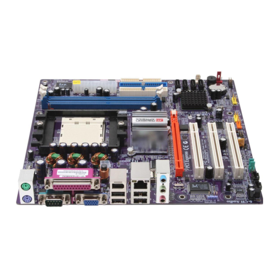
Page 10: Motherboard Components
Motherboard Components Introducing the Motherboard... - Page 11 Table of Motherboard Components LABEL COMPONENT 1 CPU Socket Socket 939 for AMD K8 processor 2 CPU_FAN CPU cooling fan connector 3 DIMM1~2 184-pin DDR SDRAM slots 4 ATX_POWER Standard 24-pin ATX power connector 5 FDD Floppy diskette drive connector 6 IDE1 Primary IDE channel 7 IDE2...
- Page 12 Memo Introducing the Motherboard...
-
Page 13: Installing The Motherboard
Make sure that your case supports all the features required. Secondly, RS482-M supports one or two floppy diskette drives and four enhanced IDE drives. Make sure that your case has sufficient power and space for all drives that you intend to install. -
Page 14: Checking Jumper Settings
Do not over-tighten the screws as this can stress the motherboard. Checking Jumper Settings This section explains how to set jumpers for correct configuration of the motherboard. Setting Jumpers Use the motherboard jumpers to set system configuration options. Jumpers with more than one pin are numbered. -
Page 15: Checking Jumper Settings
Checking Jumper Settings The following illustration shows the location of the motherboard jumpers. Pin 1 is labeled. Jumper Settings Type Jumper Description Setting (default) 1-2: CLEAR CLR_CMOS 2-3: NORMAL CLR_CMOS 3-pin CLEAR CMOS Before clearing the CMOS, make sure to turn off the system. -
Page 16: Connecting Case Components
Connecting Case Components After you have installed the motherboard into a case, you can begin con- necting the motherboard components. Refer to the following: Connect the CPU cooling fan cable to CPU_FAN. Connect the system cooling fan connector to SYS_FAN. Connect the power fan connector to PWR_FAN. - Page 17 CPU_FAN/SYS_FAN/PWR_FAN: FAN Power Connectors Signal Name Function System Ground Power +12V +12V Sense Sensor ATX12V: ATX 12V Power Connector Signal Name Ground Ground +12V +12V ATX_POWER: ATX 24-pin Power Connector Signal Name Signal Name +3.3V +3.3V +3.3V -12V Ground PS_ON Ground Ground PWRGD...
-
Page 18: Front Panel Connector
Front Panel Connector The front panel connector (PANEL1) provides a standard set of switch and LED connec- tors commonly found on ATX or micro-ATX cases. Refer to the table below for informa- tion: Signal Function Signal Function HD_LED_P Hard disk LED(+) FP PWR/SLP *MSG LED(+) HD_LED_N Hard disk LED(-) FP PWR/SLP *MSG LED(-) -
Page 19: Installing Hardware
Installing Hardware Installing the Processor Caution: When installing a CPU heatsink and cooling fan make sure that you DO NOT scratch the motherboard or any of the surface-mount resistors with the clip of the cooling fan. If the clip of the cooling fan scrapes across the motherboard, you may cause serious damage to the motherboard or its components. -
Page 20: Cpu Installation Procedure
CPU Installation Procedure The following illustration shows CPU installation components. Install your CPU. Pull up the lever away from the socket and lift up to 90-degree angle. Locate the CPU cut edge (the corner with the pin hold noticeably missing). Align and insert the CPU correctly. -
Page 21: Installing Memory Modules
Installing Memory Modules This motherboard accomodates two memory modules. It can support two 184-pin 2.5V unbuffered DIMM, DDR 400/333/266. The maximum memory capacity is 2GB. DDR SDRAM memory module table Memory module Memory Bus DDR 266 133MHz DDR 333 166MHz DDR 400 200MHz You must install at least one module in any of the two slots. - Page 22 Table A: DDR 400 QVL (Qualified Vendor List) Size Vendor Model Name 256MB APACER AM3A568ACT05A CORSAIR PLATNUM CMX512-3200C2PT GEIL GE08L3264D1WL5NKT3H71 GEIL G208L364D1TG5NKT3C Hynix HY5DU56822BT-D43 Kingston D3208DL2T-5 0323PT01 Kingston Samsung K4H560838D-TCC4 Kingston Winbond W942508BH-5 Ramaxel MIC-R 46V32M8TG-5BC Ramaxel Samsung K4H560838D-TCC4 Samsung K4H560838D-TCCC Soutec M2G9108AKAS09F083S9DT...
-
Page 23: Installing A Hard Disk Drive/Cd-Rom/Sata Hard Drive
Installing a Hard Dish Drive/CD-ROM/SATA Hard Drive This section describes how to install IDE devices such as a hard disk drive and a CD-ROM drive. About IDE Devices Your motherboard has two IDE channel interfaces (IDE1 & IDE2). Two IDE ribbon cables supporting four IDE devices is bundled with the motherboard. - Page 24 About SATA Connectors This motherboard features four SATA connectors supporting a total of four drives. SATA , or Serial ATA (Advanced Technology Attachment) is the standard interface for the IDE hard drives which are currently used in most PCs. These connectors are well designed and will only fit in one orientation.
-
Page 25: Installing A Floppy Diskette Drive
Installing a Floppy Diskette Drive The motherboard has a floppy diskette drive (FDD) interface and ships with a diskette drive ribbon cable that supports one or two floppy diskette drives. You can install a 5.25-inch drive and a 3.5-inch drive with various capacities. The floppy diskette drive cable has one type of connector for a 5.25-inch drive and another type of connector for a 3.5-inch drive. -
Page 26: Installing Add-On Cards
Installing Add-on Cards The slots on this motherboard are designed to hold expansion cards and connect them to the system bus. Expansion slots are a means of adding or enhancing the motherboard’s features and capabilities. With these efficient facilities, you can increase the motherboard’s capabili- ties by adding hardware that performs tasks that are not part of the basic system. - Page 27 Follow these instructions to install an add-on card: Remove a blanking plate from the system case corresponding to the slot you are going to use. Install the edge connector of the add-on card into the expansion slot. Ensure that the edge connector is correctly seated in the slot. Secure the metal bracket of the card to the system case with a screw.
-
Page 28: Connecting Optional Devices
Connecting Optional Devices Refer to the following for information on connecting the motherboard’s optional devices: AUDIO1: Front Panel Audio header This header allows the user to install auxiliary front-oriented microphone and line-out ports for easier access. Signal Name Function AUD_MIC Front Panel Microphone input signal AUD_GND Ground used by Analog Audio Circuits... - Page 29 CD_IN: Analog audio input header Signal Name Function CD In left channel CD in_L Ground Ground CD In right channel CD in_R SATA1/2/3/4: Serial ATA connectors These connectors are use to support the new Serial ATA devices for the highest date transfer rates (150 MB/s), simpler disk drive cabling and easier PC assembly.
- Page 30 COM2: Onboard serial port header (optional) Connect a serial port extension bracket to this header to add a second serial port to your system. Signal Name Function NDCDB Data carry detect NSINB Serial Data In NSOUTB Serail Data Out NDTRB Data terminal ready Ground NDSRB...
- Page 31 AUX_IN: Auxliary In header (optional) Signal Name Function AUX In left channel AUX_L Ground Ground AUX In right channel AUX_R Installing the Motherboard...
-
Page 32: Connecting I/O Devices
Connecting I/O Devices The backplane of the motherboard has the following I/O ports: PS2 Mouse Use the upper PS/2 port to connect a PS/2 pointing device. PS2 Keyboard Use the lower PS/2 port to connect a PS/2 keyboard. Parallel Port Use LPT1 to connect printers or other parallel communications (LPT1) devices. -
Page 33: Using Bios
Chapter 3 Using BIOS About the Setup Utility The computer uses the latest Award BIOS with support for Windows Plug and Play. The CMOS chip on the motherboard contains the ROM setup instructions for configuring the motherboard BIOS. The BIOS (Basic Input and Output System) Setup Utility displays the system’s configura- tion status and provides you with options to set system parameters. -
Page 34: Bios Navigation Keys
Press DEL to enter SETUP Pressing the delete key accesses the BIOS Setup Utility: Phoenix-AwardBIOS CMOS Setup Utility: Standard CMOS Features Frequency/Voltage Control Advanced BIOS Features Load Fail-Safe Defaults Advanced Chipset Features Load Optimized Defaults Integrated Peripherals Set Supervisor Password Power Management Setup Set User Password PnP/PCI Configurations... -
Page 35: Updating The Bios
Updating the BIOS You can download and install updated BIOS for this motherboard from the manufacturer’s Web site. New BIOS provides support for new peripherals, improvements in performance, or fixes for known bugs. Install new BIOS as follows: If your motherboard has a BIOS protection jumper, change the setting to allow BIOS flashing. -
Page 36: Standard Cmos Features
Standard CMOS Features This option displays basic information about your system. Phoenix-AwardBIOS CMOS Setup Utility Standard CMOS Features Date (mm:dd:yy) Wed, Jan 25 2005 Item Help Time (hh:mm:ss) 9 : 33 : 26 Menu Level IDE Channel 0 Master IDE Channel 0 Slave Change the day, month, IDE Channel 1 Master year and century... - Page 37 If you are setting up a new hard disk drive that supports LBA mode, more than one line will appear in the parameter box. Choose the line that lists LBA for an LBA drive. IDE Channel 0/1 Master/Slave IDE/Extended IDE Drives (Auto) Leave this item at Auto to enable the system to automatically detect and configure IDE devices on the channel.
-
Page 38: Advanced Bios Features
Advanced BIOS Features This option defines advanced information about your system. Phoenix-AwardBIOS CMOS Setup Utility Advanced BIOS Features Hard Disk Boot Priority [Press Enter] Item Help CPU Internal Cache [Enabled] External Cache [Enabled] Menu Level Quick Power On Self Test [Enabled] Select Hard Disk First Boot Device... - Page 39 First/Second/Third Boot Device (Floppy/Hard Disk/CDROM) Use these three items to select the priority and order of the devices that your system searches for an operating system at start-up time. Boot Other Device (Enabled) When enabled, the system searches all other possible locations for an operating system if it fails to find one in the devices specified under the First, Second, and Third boot devices.
-
Page 40: Advanced Chipset Features
The disk drive software monitors the internal performance of the motors, media, heads and electronics of the drive. The host software monitors the overall reliability status of the drive. If a device failure is predicted, the host software, through the Client WORKS S.M.A.R.T applet, warns the user of the impending condition and advises appropriate action to protect the data. - Page 41 Timing Mode (Auto) This item allows you to set up the DRAM timing nanually or automatically. Memclock index value (Mhz) (200MHz) When DDR Timing Setting by is set to Manual, use this item to set the DRAM frequency. CAS# latency (Tcl) (2.5) This item determines the operation of SDRAM memory CAS (column address strobe).
-
Page 42: Integrated Peripherals
Video RAM Cacheable [Enabled] This item allows users to enable or disable the video ram cacheable function. System BIOS Cacheable (Enabled) This feature is only valid when the system BIOS is shadowed. It enables or disables the caching of the system BIOS ROM at F0000h-FFFFFh via the L2 cache. This greatly speeds up accesses to the system BIOS. - Page 43 South OnChip IDE Device (Press Enter) Scroll to this item and press <Enter> to view the following screen: Phoenix-AwardBIOS CMOS Setup Utility SIS OnChip IDE Device Item Help IDE DMA transfer access [Enabled] Onchip IDE Channel0 [Enabled] Menu Level Onchip IDE Channel1 [Enabled] IDE Prefetch Mode [Enabled]...
- Page 44 South OnChip PCI Device (Press Enter) Scroll to this item and press <Enter> to view the following screen: Phoenix-AwardBIOS CMOS Setup Utility SIS OnChip PCI Device Item Help Onboard AC97 AUDIO [Auto] Onboard PCI LAN [Enabled] Menu Level Onboard Lan Boot ROM [Disabled] Onboard 1394 [Enabled]...
- Page 45 Onboard SuperIO Device (Press Enter) Scroll to this item and press <Enter> to view the following screen: Phoenix-AwardBIOS CMOS Setup Utility Onboard SuperIO Device Item Help Onboard FDC Controller [Enabled] Onboard Serial Port 1 [3F8/IRQ4] Menu Level Onboard Parallel Port [378/IRQ7] Parallel Port Mode [ECP]...
-
Page 46: Power Management Setup
Power Management Setup This option lets you control system power management. The system has various power- saving modes including powering down the hard disk, turning off the video, suspending to RAM, and software power down that allows the system to be automatically resumed by certain events. - Page 47 Resume Event Control (Press Enter) Scroll to this item and press <Enter> to view the following screen: Phoenix-AwardBIOS CMOS Setup Utility Resume Event Control Resume By PCI PME [Enabled] Item Help Resume By WOL/WOM/Ring [Disabled] RTC Alarm Resume [Disabled] Menu Level Date (of Month) Alarm Time (hh:mm:ss) Alarm 0 0 0...
-
Page 48: Pnp/Pci Configurations
PNP/PCI Configurations These options configure how PnP (Plug and Play) and PCI expansion cards operate in your system. Both the the ISA and PCI buses on the motherboard use system IRQs (Interrup ReQuests) and DMAs (Direct Memory Access). You must set up the IRQ and DMA assignments correctly through the PnP/PCI Configurations Setup utility for the motherboard to work properly. -
Page 49: Pc Health Status
PC Health Status On motherboards that support hardware monitoring, this item lets you monitor the parameters for critical voltages, temperatures and fan speeds. Phoenix-AwardBIOS CMOS Setup Utility PC Health Status Item Help Shutdown Temperature [Disabled] Warning Temperature [Disabled] Menu Level CPU Vcore Voltage +2.5V +3.3V... -
Page 50: Frequency/Voltage Control
Frequency/Voltage Control This item enables you to set the clock speed and system bus for your system. The clock speed and system bus are determined by the kind of processor you have installed in your system. Phoenix-AwardBIOS CMOS Setup Utility Frequency/Voltage Control Item Help AMD K8 Cool ‘n’... -
Page 51: Load Fail-Safe Settings
Load Fail-Safe Defaults This option opens a dialog box that lets you install fail-safe defaults for all appropriate items in the Setup Utility: Press <Y> and the <Enter> to install the defaults. Press <N> and then <Enter> to not install the defaults. The fail-safe defaults place no great demands on the system and are generally stable. -
Page 52: Save & Exit Setup
Save & Exit Setup Highlight this item and press <Enter> to save the changes that you have made in the Setup Utility and exit the Setup Utility. When the Save and Exit dialog box appears, press <Y> to save and exit, or press <N> to return to the main menu. Exit Without Saving Highlight this item and press <Enter>... -
Page 53: Using The Motherboard Software
Chapter 4 Using the Motherboard Software About the Software CD-ROM The support software CD-ROM that is included in the motherboard package contains all the drivers and utility programs needed to properly run the bundled products. Below you can find a brief description of each software program, and the location for your motherboard version. -
Page 54: Running Setup
Setup Tab Setup Click the Setup button to run the software installation program. Select from the menu which software you want to install. Browse CD The Browse CD button is the standard Windows command that allows you to open Windows Explorer and show the contents of the support Before installing the software from Windows Explorer, look for a file named README.TXT, INSTALL.TXT or something similar. - Page 55 Click Next. The following screen appears: Check the box next to the items you want to install. The default options are recommended. Click Next run the Installation Wizard. An item installation screen appears: Follow the instructions on the screen to install the items. Drivers and software are automatically installed in sequence.
-
Page 56: Manual Installation
Manual Installation Insert the CD in the CD-ROM drive and locate the PATH.DOC file in the root directory. This file contains the information needed to locate the drivers for your motherboard. Look for the chipset and motherboard model; then browse to the directory and path to begin installing the drivers. - Page 57 Caractéristiques Processeur La RS482-M utilise un socket de 939 broches ayant les caractéristiques suivantes : • Peut recevoir les processeurs AMD Athlon64/Athlon 64 FX • Prend en charge des vitesses d’interface HyperTransport (HT) allant jusqu’à 2000MT/s La Technologie HyperTransport est une liaison point à point entre deux matériels, elle permet à...
- Page 58 Une interface de lecteur de disquette • Quatre connecteurs SATA à 7 broches La RS482-M carte mère prenant en charge la maîtrise de bus UltraDMA avec vitesses de transfert de 133/100/66/33 Mo/s. E/S intégrées La carte mère possède un jeu complet de ports d’E/S et de connecteurs: •...
- Page 59 Feature Prozessor Das RS482-M verwendet einen 939-Pin Socket mit den folgenden Merkmalen: • Nimmt AMD Athlon64/Athlon 64 FX Prozessoren auf • Unterstützt bis zu 2000MT/s HyperTransport (HT) Interface- Geschwindigkeiten HyperTransport Technologie ist ein Punkt-zu-Punkt Link zwischen zwei Geräten. Es ermöglicht integrierten Schaltkreisen einen Informationsaustausch mit wesentlich höherer Geschwindigkeit als bei gängigen Interconnect-Technologien.
- Page 60 Zwei 40-Pin IDE Stecker, vier IDE-Kanäle unterstützen • Ein Steckplatz für ein Diskettenlaufwerk • Vier 7-Pin SATA-Stecker Die RS482-M-Motherboard unterstützt UltraDMA Bus Mastering mit einer Übertragungsrate von 133/100/66/33 MB/Sek. Integrierte I/O-Schnittstellen Das Motherboard verfügt über einen kompletten Satz von I/O-Schnittstellen und Anschlüssen: •...
- Page 61 Caratteristiche Processore RS482-M è dotata di una presa a 939 pin che offre le seguenti caratteristiche: • Compatibilità con processori AMD Athlon64/Athlon 64 FX • Supporto di velocità di interfaccia HyperTransport (HT) fino a 2000 MT/s La tecnologia HyperTransport consente il collegamento point-to-point fra due dispositivi e quindi un trasferimento di informazioni tra circuiti integrati molto più...
- Page 62 Un’interfaccia per unità disco floppy • Quattro connettori SATA a 7 pin La scheda madre RS482-M supporta bus master UltraDMA con tasso di trasferimento di 133/100/66/33 MB/s. integrati La scheda madre offre una serie completa di porte e connettori I/O: •...
- Page 63 Característica Procesador La RS482-M usa un zócalo 939-pin que lleva las sigtes. características: • Acomoda procesadores AMD Athlon64/Athlon 64 FX • Soporta hasta las velocidades de interfaz 2000MT/s HyperTransport (HT) La Tecnología HyperTransport es un vínculo punto a punto entre dos dispositivos, habilita circuitos integrados para intercambiar la información en velocidades más rápidas que las...
- Page 64 Una interfaz de la unidad de disco floppy • Cuatro conectores SATA de 7-pin La placa principal RS482-M soporta el mastering de bus UltraDMA con índices de transferencia de 133/100/66/33 MB/s. I/O Integrado La placa principal tiene un juego completo de puertos y conectores I/O: •...
- Page 65 Características Processador O RS482-M usa uma ficha de 939 pinos que comporta as seguintes características: • Acomoda processadores AMD Athlon64/Athlon 64 FX • Suporta velocidades de interface de HyperTransportTM (HT) até 2000MT/ Tecnologia de HyperTransport Té um link ponto-a-ponto entre dois dispositivos, permite circuitos integrados para trocar informação a velocidades muito mais elevadas que as...
- Page 66 Um interface com drive de disco flexível • Quatro conectores SATA de 7 pin A motherboard RS482-M suporta um domínio bus UltraDMA bus com taxas de Transferência de 133/100/66/33 MB/s. I/O Integrado A motherboard possui um conjunto completo de portas I/O e conectores: •...
- Page 67 機能 プロセッサ RS482-M が採用した939ピン仕様のソケットは、次の特徴があります: • AMD Athlon64/Athlon 64 FX プロセッサを搭載可能 • 転送率が最大2000MT/秒までの HyperTransport (HT)インターフェース を採用 HyperTransport 技術とは、二つのデバイスを1対1( point-to-point)で接続する技 術であり、従来のインターコネクト技術に比較して、集積回路同士の情報交換を高速化 します。 チップセット RS482 Northbridge (NB)と SB400 Southbridge (SB)チップセットは、実証された信 頼性と性能を持つ革新的で拡張性のあるアーキテクチャに基づいています。 • RS482 (NB) 1つの x2 ( x4に拡張可能) A-Link Express インターフェース (PCI Express 1.0a に対応)でATI IXPに接続...
- Page 68 オンボードLAN (オプション) 当マザーボードは次のLANチップセットのいずれかを搭載しております: • 10/100Mbps N-way自動ネゴシエーション操作をサポート • Wake-On-LANと遠隔wake-up機能をサポート • ネットワーク状態インジケータ用のLEDピンを搭載 • 全二重フロー制御(IEEE 802.3x)をサポート • 10/100/1000 トランシーバーを搭載済み • PCI v2.3, 32-bit, 33/66-MHzへの対応 • クロスオーバー検出機能と自動修正機能を搭載 • Wake-on-LANと遠隔 wake-upとの機能をサポート 拡張オプション 本マザーボードでは、次の拡張機能が利用できます。 • グラフィック用のPCI Express x16 インターフェース x1 • 32ビットPCI v2.3 互換性スロット x2 • 40ピンIDEロープロフィルヘッダー(4つのIDEチャネルをサポート)が2つ...
- Page 69 특성 프로세서 RS482-M 는 939 핀 소켓을 사용하여 다음과 같은 특성을 지닌다: • AMD 애슬론 64/애슬론 64 FX 프로세서 사용 • HyperTransport (HT) 인터페이스 속도 최대 2000MT/s 지원 HyperTransport 기술은 두 장치간의 point-to-point 링크로, 집적 회로가 기존의 상호 연결 기술 보다 더 빠른 속도로 정보를 교환할 수 있다.
- Page 70 최대 4개의 IDE 장치를 지원하는 40핀IDE 커넥터 2 개 • 플로피 디스크 드라이브 인터페이스 1 개 • 7 핀 SATA 커넥터 4 개 RS482-M 마더보드는 전송 속도 133/100/66/33 MB/s의 UltraDMA 버스 마스터링을 지 원한다. 통합 I/O 본 마더보드는 풀 셋트의 I/O 포트 및 커넥터가 있다: •...
- Page 71 功能 處理器 RS482-M採用1個939針插槽,該插槽具有如下特徵: • 可安裝AMD Athlon64/Athlon 64 FX 處理器 • 支援高達2000MT/秒的HyperTransport (HT)介面傳輸速率 HyperTransport 技術為以點對點方式連接兩台設備的技術,藉此,積體電路間能夠以 後高於現有各種內部連接技術(interconnect technology)技術的速度來交換資訊。 晶片組 RS482 北橋(NB)及SB400 南橋(SB)晶片組在研發設計上採用了創新且具擴充性之架構, 具備優良的可靠性及性能。 RS482 (NB) • 1個 2倍速 (可擴充至4倍速) A-Link Express介面 (PCI Ex- press 1.0a 相容) 以連接ATI IXP • 支援1個繪圖介面用之PCI Express x16,完全符合PCI Express Base規格修訂版1.0a...
- Page 72 內建區域網路 (選購) 本主機板搭載有如下其中一種LAN晶片組: • 支援 10/100Mbps N-way 自動協調作業 • 支援區域網路喚醒(Wake-On-LAN)及遠端喚醒功能 • 配有各種網路活動指示器用之LED接腳 • 支援全雙工流量控制(IEEE 802.3x) • 整合有10/100/1000 收發器 • 支援PCI v2.3, 32位元, 33/66-MHz • 具有跳接線偵測及自動修正功能 • 支援區域網路喚醒功能及遠距喚醒功能 擴充選項 本主機板包括下列擴充選項: • 1 個繪圖卡用PCI Express x16 介面 • 3 個32位元PCIv2.3插槽 • 2 個 40針 IDE 接頭,支援 4個 IDE 裝置 •...
- Page 73 功能 处理器 RS482-M 主板使用一个 939-pin 插座,此插座具有以下特点: • 支持 AMD Athlon64/Athlon 64 FX 处理器 • 支持 2000MT/s HyperTransport (HT) 接口速度 HyperTransport 技术是一种在两台设备间进行点到点连接的技术,它可以让集成电 路使用比当前互连技术更高的速度进行信息交换。 芯片组 RS482 北桥 (NB) 和 SB400 南桥 (SB) 芯片组是基于一种新型的、可扩展的架构,能 提供已经证明的可靠性和高性能。 RS482 (NB) • 1 x2 (可扩展到 x4) A-Link Express 接口(符合 PCI Express 1.0a 标准)用于连接到...
-
Page 74: Onboard Lan
3 个 • 2 个 40-pin IDE 接口,可支持 4 个 IDE 设备 • 1 个软驱接口 • 4 个 7-pin SATA 接口 主板 RS482-M支持 Ultra DMA 总线控制,传输速率可达 133/100/66/33MB/s。 集成 I/O 此主板具有完整的 I/O 端口和插孔: • 2 个用于连接鼠标和键盘的 PS/2 端口 • 1 个串口... - Page 75 Характеристики Процессор Плата RS482-M использует 939-штырьковый сокет и обладает следующими характеристиками: -Размещает процессоры AMD Athlon64/Athlon 64 FX -Поддерживает технологию 2000MT/s HyperTransport (HT) Технология HyperTransport обеспечивает связь двух устройств по протоколу point- to-point, позволяя гораздо более быстрый обмен информацией между интегральными...
- Page 76 • Один разъем для накопителя на гибких дисках • Четыре разъема 7-pin SATA Плата RS482-M поддерживает технологию захвата управления шиной UltraDMA bus mastering со скоростью передачи данных 133/100/66/33 МБ/сек. Интегрированный вход/выход Плата снабжена полным набором портов входа/выхода и разъемов: •...
- Page 77 Cechy Procesor Płyta główna RS482-M dostosowana jest do 939-nóżkowego gniazda i posiada następujące właściwości: • Przystosowana do procesorów firmy AMD Athlon64/Athlon 64 FX • Obsługuje złącze HyperTransport (HT) z szybkością do 2000MT/s Technologia HiperTransportu jest protokołem komunikacji między dwoma urządzeniami, który umożliwia układom zcalonym wymieniać...
- Page 78 Dwa 40-nóżkowe złącza IDE mogące obsłużyć do czterech urządzeń IDE • Jedno złącze obsługujące stacje dyskietek • Cztery 7-nóżkowe złącza SATA Płyta główna RS482-M obsługuje szynę UltraDMA z szybkością transferu 133/100/66/33 MB/s. Zintegrowane We/Wy Płyta głwna wyposażona jest w pełny zestaw gniazd i złączy We/Wy: •...
- Page 79 Vlastnosti Procesor Základní deska RS482–M využívá 939kolíkovou patici nabízející následující vlastnosti: • Podpora procesorů AMD Athlon 64/Athlon 64 FX • Podpora rychlostí rozhraní HyperTransport (HT) až 2000 MT/s Technologie HyperTransport je přímým spojením mezi dvěma zařízeními, umožňující integrovaným obvodům výměnu informací vyššími rychlostmi, než jaké nabízejí současné technologie.
- Page 80 Dva 40kolíkový konektor IDE podporující až čtyři zařízení IDE • Jedno rozraní pro disketovou mechaniku • Čtyři 7kolíkové konektor SATA Základní deska RS482-M podporuje sběrnici Ultra DMA s přenosovými rychlostmi 133/100/66/33 MB/s. Integrovaný vstup/výstup Základní deska je vybavena kompletní sadou vstupních portů a konektorů I/O: •...
- Page 81 Caracteristici Procesorul RS482-M utilizează un soclu de 939 de ace care are următoarele caracteristici: • Funcţionează cu procesoare AMD Athlon64/Athlon 64 FX • Suportă interfeţe HyperTransport (HT) cu viteze de până la 2000 MT/s Tehnologia HyperTransport este o legătură punct-la-punct între două aparate, care permite viteze mult mai mari de schimb al informaţiilor între circuitele integrate, decât cel asigurat de...
- Page 82 O interfaţă pentru unitate floppy • Patru conectoare SATA 7 Placa de bază RS482-M suportă bus mastering UltraDMA cu viteze de transfer de 133/100/66/33 MB/s I/O integrată Placa de bază este dotată cu un set complet de porturi şi conectoare I/O: •...
- Page 83 Спецификация Процесор RS482-M използва сокет 939-pin със следните спецификации: • Поддръжка на процесори AMD Athlon64/Athlon 64 FX • Поддръжка на технологията HyperTransport (HT) със скорост до 2000MT/s Технологията HyperTransport е връзка точка-до-точка (point-to-point) между две устройства, която предоставя възможност интегрираните вериги да обменят...
- Page 84 • един конектор за флопидисково устройство • четири 7-щифтови SATA конектораs Дънната платка RS482-M поддържа шина UltraDMA 133/100/66/33 MB/s Интегриран Вход/Изход контролер Дънната платка има пълен набор от I/O портове и конектори: • два PS/2 порта за мишка и клавиатура...
- Page 85 Jellemző Processzor Az RS482-M 939 tűs foglalattal rendelkezik, ennek jellemzői pedig a következők: • AMD Athlon64/Athlon 64 FX processzorokkal működik • Maximum 2000 MT/s HyperTransport (HT) sebességű interfészt támogat A HyperTransport technológia egy ponttól pontig való kapcsolat két készülék között, és segítségével az integrált áramkörök közötti információcsere sebessége sokkal nagyobb, mint a...
- Page 86 Két 40 tűs IDE csatlakozó négy IDE eszköz támogatására • Egy hajlékonylemez meghajtó interfész • Négy 7 tűs SATA csatlakozó A RS482-M alaplap támogatja az UltraDMA bus mastering megoldást, 133/100/66/33 MB/s sebességen Beépített I/O Az alaplapot az I/O portok és csatlakozók teljes készletével szerelték fel: •...
Need help?
Do you have a question about the RS482-M and is the answer not in the manual?
Questions and answers