Page 2
Preface Copyright This publication, including all photographs, illustrations and software, is protected under international copyright laws, with all rights reserved. Neither this manual, nor any of the material contained herein, may be reproduced without written consent of the author. Version 1.0 Disclaimer The information in this document is subject to change without notice.
Page 3
Declaration of Conformity This device complies with part 15 of the FCC rules. Operation is subject to the following conditions: This device may not cause harmful interference, and • This device must accept any interference received, including interference • that may cause undesired operation. This device is in conformity with the following EC/EMC directives: Electromagnetic compatibility of multimedia equipment - Emission ...
TABLE OF CONTENTS Preface Chapter 1 Introducing the Motherboard Introduction...................1 Pakage Contents................1 Specifications................2 
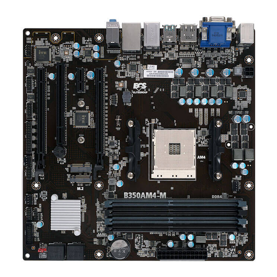
Motherboard Components............4 I/O Ports....................6 Chapter 2 Installing the Motherboard Safety Precautions................7 Installing the Motherboard in a Chassis........7 Checking Jumper Settings..............8 Installing Hardware..............9 Installing the Processor.............9 Installing the CPU Cooler............10 Installing Memory Modules............11 Installing Add-on Cards............13 Connecting Optional Devices..........16...
Page 5
Using the Motherboard Software Auto-installing under Windows 10/7..........65 ..Running Setup..............65 Manual Installation................67 ECS Utility Software (Intelligent EZ Utility)........67 Chapter 5 Setting Up AMD B350 RAID Configuration Setting Up a Bootable RAID Array..........69 Chapter 6 Trouble Shooting Start up problems during assembly..........81 Start up problems after prolong use..........82...
Chapter 1 Introducing the Motherboard Introduction Thank you for choosing the B350AM4-M motherboard. This motherboard is a high performance, enhanced function motherboard designed to support the ® RYZEN Series processors and 7th Gen A-series / Athlon Processors for socket AM4. This motherboard is based on AMD B350 Express Chipset for best desktop platform ®...
RYZEN Series processors and 7th Gen A-series / Athlon Processors for socket AM4 • Supports CPU up to 95W TDP Note: Please go to ECS website for the latest CPU support list. Chipset • AMD B350 Chipset Memory • Dual-channel DDR4 memory architecture •...
Page 8
• 1 x 10-pin USB 2.0 header supports additional two USB 2.0 ports • 1 x 5-pin USB 2.0 header supports additional one USB 2.0 ports • 2 x Serial port headers (COM) • 1 x LPT header • 1 x CLR_CMOS jumper •...
I/O Ports 1. PS/2 Mouse(green) Use the upper PS/2 port to connect a PS/2 mouse. 2. PS/2 Keyboard(purple) Use the lower PS/2 port to connect a PS/2 keyboard. 3. VGA Port Connect your monitor to the VGA port. 4. DVI Port Connect your monitor to the DVI port.
Chapter 2 Installing the Motherboard 2-1. Safety Precautions Follow these safety precautions when installing the motherboard: • Wear a grounding strap attached to a grounded device to avoid damage from static electricity. • Discharge static electricity by touching the metal case of a safely grounded object before working on the motherboard.
2-3. Checking Jumper Settings The following illustration shows the location of the motherboard jumpers. Pin 1 is labeled. To avoid the system instability after clearing CMOS, we recommend users to enter the main BIOS setting page to “Load Default Settings” and then “Save and Exit Setup”.
2-4. Installing Hardware 2-4-1. Installing the Processor • This motherboard has an AM4 socket. • When choosing a processor, consider the performance requirements of the system. Performance is based on the processor design, the clock speed and system bus frequency of the processor, and the quantity of internal cache memory and external cache memory.
2-4-2. Installing the CPU Cooler • Install the cooling fan in a well-lit work area so that you can clearly see the motherboard and processor socket. • Avoid using cooling fans with sharp edges in case the fan casing and the clips cause serious damage to the motherboard or its components.
2-4-3. Installing Memory Modules • This motherboard accommodates four memory modules. It can support four 288-pin DDR4 2667/2400/2133 MHz. • Do not remove any memory module from its antistatic packaging until you are ready to install it on the motherboard. Handle the modules only by their edges.
Page 17
Recommend memory configuration Sockets Model DIMM1 DIMM2 DIMM3 DIMM4 1 DIMM Populated 1 DIMM Populated 2 DIMMs Populated Populated 3 DIMMs Populated Populated Populated 3 DIMMs Populated Populated Populated 4 DIMMs Populated Populated Populated Populated Due to AMD CPU spec definition, please follow the table above for recommended memory configuration.
2-4-4. Installing Add-on Cards The slots on this motherboard are designed to hold expansion cards and connect them to the system bus. Expansion slots are a means of adding or enhancing the motherboard’s features and capabilities. With these efficient facilities, you can increase the motherboard’s capabilities by adding hardware that performs tasks that are not part of the basic system.
Page 19
Follow these instructions to install an add-on card: Remove a blanking plate from the system case corresponding to the slot you are going to use. Install the edge connector of the add-on card into the expansion slot. Ensure that the edge connector is correctly seated in the slot. Secure the metal bracket of the card to the system case with a screw.
Page 20
Please refer the following steps to install the M.2 SSD card: Demount the screw not used according to the length of your M.2 SSD card. Insert the M.2 SSD card into NGFF slot in the fool-proof way. Lock the screw as the following picture shows to make sure the M.2 SSD card is installed in place.
2-4-5. Connecting Optional Devices Refer to the following for information on connecting the motherboard’s optional devices: Components Components SATA3_1~4 F_USB2 COM1~2 USB3F CASE F_USB1 F_AUDIO 1. SATA3_1~4: Serial ATA Connectors SATA3_1~4 connectors are used to support the Serial ATA 6Gb/s device, simpler disk drive cabling and easier PC assembly.
Page 22
2. FUSB2: 5-pin Front Panel USB 2.0 Header The motherboard has one 5-pin USB 2.0 header supporting one USB 2.0 port. Please make sure that the USB cable has the same pin assignment as indicated above. A different pin assignment may cause damage or system hang-up.
Page 23
4. FUSB1: Front Panel USB 2.0 Header The motherboard has one USB 2.0 header supporting two USB 2.0 ports. Additionally, some computer cases have USB ports at the front of the case. If you have this kind of case, use auxiliary USB connector to connect the front-mounted ports to the motherboard.
Page 24
6. COM1~2: Onboard Serial Port Header Connect a serial port extension bracket to this header to add a serial port to your system. 7. CASE: Chassis Intrusion Detect Header This detects if the chassis cover has been removed. This function needs a chassis equipped with instrusion detection switch and needs to be enabled in BIOS.
Page 25
8. F_AUDIO: Front Panel Audio Header The front panel audio header allows the user to install auxiliary front-oriented microphone and line-out ports for easier access. This header supports HD audio by default. If you want connect an AC’ 97 front panel audio to HD onboard headers, please set as below picture.
2-4-6. Installing a SATA Hard Drive This section describes how to install a SATA Hard Drive. About SATA Connectors Your motherboard features four SATA connectors supporting a total of four drives. SATA refers to Serial ATA (Advanced Technology Attachment) is the standard interface for the IDE hard drives which are currently used in most PCs.
2-4-7. Connecting Case Components After you have installed the motherboard into a case, you can begin connecting the motherboard components. Refer to the following: Components Components CPU_FAN F_PANEL ATX_POWER ATX12V SYS_FAN1~2 B350AM4-M USER MANUAL...
Page 28
1. CPU_FAN (CPU cooling FAN Power Connector) & 3. SYS_FAN1~2 (System Cooling FAN Power Connector) Connect the CPU cooling fan cable to CPU_FAN. Connect the system cooling fan connector to SYS_FAN1~2. Users please note that the fan connector supports the CPU cooling fan of 1.1A ~ 2.2A (26.4W max) at +12V.
Connecting 24-pin power cable The ATX 24-pin connector allows you to connect to ATX_POWER power supply. With ATX_POWER power supply, users please note that when installing 24-pin power cable, the latches of power cable and the ATX_POWER match perfectly. 24-pin power cable Connecting 4-pin power cable The ATX12V power connector is used to provide power to the CPU.
Page 30
Hard Drive Activity LED Connecting pins 1 and 3 to a front panel mounted LED provides visual indication that data is being read from or written to the hard drive. For the LED to function properly, an IDE drive should be connected to the onboard IDE interface. The LED will also show activity for devices connected to the SCSI (hard drive activity LED) connector.
Chapter 3 Using BIOS About the Setup Utility The computer uses the latest “American Megatrends Inc. ” BIOS with support for Windows Plug and Play. The CMOS chip on the motherboard contains the ROM setup instructions for configuring the motherboard BIOS. The BIOS (Basic Input and Output System) Setup Utility displays the system’s configuration status and provides you with options to set system parameters.
Press the delete key to access BIOS Setup Utility. Resetting the Default CMOS Values When powering on for the first time, the POST screen may show a “CMOS Settings Wrong” message. This standard message will appear following a clear CMOS data at factory by the manufacturer.
Using BIOS When you start the Setup Utility, the main menu appears. The main menu of the Setup Utility displays a list of the options that are available. A highlight indicates which option is currently selected. Use the cursor arrow keys to move the highlight to other options.
Page 35
Default Select the default icon and press <Enter> or double click the left key of the mouse to display the screen. Then you can load optimized defaults or not. Advanced Select the advanced icon and press <Enter> or double click the left key of the mouse to display the screen.
Main Menu This menu shows the information of BIOS and enables you to set the system language, date and time. Main Advanced Chipset M.I.B. X Security Boot Exit Choose the system default BIOS Information language System Language English System Date Fri 06/02/2017 System Time 00:00:16...
Advanced Menu The Advanced menu items allow you to change the settings for the CPU and other system. Main Advanced Chipset M.I.B. X Security Boot Exit LAN Configuration LAN Configuration PC Health Status Parameters Power Management Setup ACPI Settings CPU Configuration SATA Configuration USB Configuration ...
Page 38
PC Health Status On motherboards support hardware monitoring, this item lets you monitor the parameters for critical voltages, temperatures and fan speeds. Main Advanced Chipset M.I.B. X Security Boot Exit PC Health Status Smart Fan Function CPU Tct1 System Temperature CPU Fan 1 Speed 2766 RPM ...
Page 39
Smart Fan Mode (Normal) This item allows you to select the fan mode (Normal, Quiet, Silent, or Manual) for a better operation environment. If you choose Normal mode, the fan speed will be auto adjusted depending on the CPU temperature. If you choose Quite mode, the fan speed will be auto minimized for quiet environment.
Page 40
Power Management Setup This page sets up some parameters for system power management operation. Main Advanced Chipset M.I.B. X Security Boot Exit Enable/Disable functionality: Power Management Setup Resume by PCI/PCIE/USB devices, Onboard LAN Resume By PME Disabled controllers, Serial Ports Resume By PS2 KB Disabled Resume By PS2 MS...
Page 41
ACPI Settings The item in the menu shows the highest ACPI sleep state when the system enters suspend. Main Advanced Chipset M.I.B. X Security Boot Exit Select the highest ACPI sleep ACPI Settings state the system will enter ACPI Sleep State S3 (Suspend to RAM) when the SUSPEND button is pressed.
Page 42
CPU Configuration The item in the menu shows the CPU. Main Advanced Chipset M.I.B. X Security Boot Exit CPU Configuration Enable/disable C6 Socket0: AMD A8-9600 RADEON R7, 10 COMPUTE CORES 4C+6G 4 Core(s) Running @ 3124 MHz 1125 mV Processor Family: 15h Processor Model: 60h-6Fh CPUID: 00660F51 Max Speed: 3100 MHz...
Page 43
Socket0: AMD Ryzen: ZD3301BBM6IF4_37/33_Y 6 Core(s) Running @ 3345 MHz 1275 This is display-only field and displays the information of the CPU installed in your computer. Processor Family (15h) This item shows the processor family. Processor Model (60h-6Fh) This item shows the processor model. CPUID (00660F51) This item shows the CPUID.
Page 44
SATA Configuration Use this item to show the mode of serial SATA configuration options. Main Advanced Chipset M.I.B. X Security Boot Exit SATA Configuration Enabled/Disabled Serial ATA SATA Controller Enabled SATA Mode AHCI : Select Screen SATA Port1 Not Present ...
Page 45
USB Configuration Use this item to show the information of USB configuration. Main Advanced Chipset M.I.B. X Security Boot Exit USB Configuration : Select Screen /Click: Select Item Enter/Dbl Click : Select +/- : Change Opt. F1: General Help F2: Previous Values F3: Optimized Defaults F4: Save &...
Page 46
Super IO Configuration Use this item to show the information of Super IO configuration. Main Advanced Chipset M.I.B. X Security Boot Exit Set Parameters of Serial Super IO Configuration Port 1 (COMA) Super IO Chip IT8733 Serial Port 1 Configuration Serial Port 2 Configuration Parallel Port Configuration ...
Page 47
Serial Port 2 Configuration Scroll to this item and press <Enter> to view the following screen: Main Advanced Chipset M.I.B. X Security Boot Exit Serial Port 2 Configuration Enable or Disable Serial Port (COM) Serial Port Enabled Device Settings IO=2F8h;...
Page 48
Parallel Port Configuration Scroll to this item and press <Enter> to view the following screen: Main Advanced Chipset M.I.B. X Security Boot Exit Enabled or Disabled Parallel Parallel Port Configuration Port (LPT/LPTE) Parallel Port Enabled Device Settings IO=378h; IRQ=5; DMA=3; Change Settings Auto Device Mode...
Page 49
Trusted Computing Use this item to show the information of trusted computing configuration. Main Advanced Chipset M.I.B. X Security Boot Exit TPM20 Device Found To select .0: Auto (Depend on Vendor: AMD Tcg module). 1: Disabled Firmware Version: 2.10 fTPM. 2: OnBoard SPI TPM2.0 AMD fTPM switch AMD CPU fTPM...
Page 50
CBS* Use this item to show the information of AMD CBS. Main Advanced Chipset M.I.B. X Security Boot Exit AMD CBS Zen Common Options Zen Common Options UMC Common Options : Select Screen /Click: Select Item Enter/Dbl Click : Select +/- : Change Opt.
Page 51
Platform First Error Handling (Auto) Use this item to select the Platform First Error Handling: Enabled/Disabled/Auto. Enable/Disable PFEH, cloak individual banks, and mask deferred error interrupts from each bank. Core Performance Boost (Auto) Use this item to select the Core Performance Boost: Disabled/Auto. Enable IBS (Auto) Use this item to select the Enable IBS: Auto/Enabled/Disabled.
Page 52
Accept Scroll to this item and press <Enter> to view the following screen: Main Advanced Chipset M.I.B. X Security Boot Exit Accept Disable - disable this Pstate Custom - customize Custom Pstate0 Auto this Pstate WARNING - Custom Pstate1 Auto DAMAGE CUASED BY Custom Pstate2...
Page 53
Main Advanced Chipset M.I.B. X Security Boot Exit Accept Disable - disable this Pstate Custom - customize Custom Pstate0 Custom this Pstate, applicable only Pstate0 Frequency Set (Mhz) 3100 if Pcd0cDisable=FALSE Pstate0 Voltage Set (uV) 1187500 WARNING - DAMAGE Frequency (MHz) 3100 CUASED BY USE OF Voltage (uV)
Page 54
Core/Thread Enablement Scroll to this item and press <Enter> to view the following screen: Main Advanced Chipset M.I.B. X Security Boot Exit Agree Sets the number of cores to be used. Once this option Downcore control Auto has been used to remove any cores, a POWER CYCLE is required in order for future selections...
Page 55
UMC Common Options Scroll to this item and press <Enter> to view the following screen: Main Advanced Chipset M.I.B. X Security Boot Exit UMC Common Options DDR4 Common Options DDR4 Common Options DRAM Memory Mapping NVDIMM : Select Screen ...
Page 56
DRAM Timing Configuration Scroll to this item and press <Enter> to view the following screen: Main Advanced Chipset M.I.B. X Security Boot Exit DRAM Timing Configuration I Decline WARNING - DAMAGE CAUSED BY USE OF YOUR AMD PROCESSOR OU Operating your AMD processor outside of specification o I Decline I Accept...
Page 57
Common RAS Scroll to this item and press <Enter> to view the following screen: Main Advanced Chipset M.I.B. X Security Boot Exit Common RAS Enable/disable data poisoning: UMC_CH: Data Poisoning Auto EccCtrl [UcFata1En] UMC_CH: EccCtrl [WrEccEn] Should be enabled/disabled together.
Page 58
Press <Esc> to return to the DDR4 Common Options page. Press <Esc> to return to the UMC Common Options page. DRAM Memory Mapping Scroll to this item and press <Enter> to view the following screen: Main Advanced Chipset M.I.B. X Security Boot Exit...
Page 59
NVDIMM Scroll to this item and press <Enter> to view the following screen: Main Advanced Chipset M.I.B. X Security Boot Exit NVDIMM : Select Screen /Click: Select Item Enter/Dbl Click : Select +/- : Change Opt. F1: General Help F2: Previous Values F3: Optimized Defaults F4: Save &...
Page 60
AMD PBS Use this item to show the information of AMD PBS. Main Advanced Chipset M.I.B. X Security Boot Exit Primary Video Adaptor Int Graphics (IGD) : Select Screen /Click: Select Item Enter/Dbl Click : Select +/- : Change Opt. F1: General Help F2: Previous Values F3: Optimized Defaults...
Chipset Menu The chipset menu items allow you to change the settings for the North Bridge chipset, South Bridge chipset and other system. Main Advanced Chipset M.I.B. X Security Boot Exit North Bridge North Bridge Parameters. South Bridge : Select Screen ...
Page 62
South Bridge Scroll to this item and press <Enter> to view the following screen: Main Advanced Chipset M.I.B. X Security Boot Exit Select AC power state when South Bridge power is re-applied after a power failure. Restore AC Power Loss Power Off Audio Configuration Azalia Internal HDMI Codec...
M.I.B. X Menu This page enables you to set the clock speed and system bus for your system. The clock speed and system bus are determined by the kind of processor you have installed in your system. Main Advanced Chipset M.I.B.
Page 64
Socket0: AMD A8-9600 RADEON R7, 10 COMPUTE CORES 4C+6G 4 Core(s) Running @ 3124 MHz 1125 mV This is display-only field and displays the information of the CPU installed in your computer. Socket0: AMD Ryzen: ZD3301BBM6IF4_37/33_Y 6 Core(s) Running @ 3345 MHz 1275 This is display-only field and displays the information of the CPU installed in your computer.
Security Menu This page enables you to set setup administrator password and user password. Main Advanced Chipset M.I.B. X Security Boot Exit Set Administrator Password Administrator Password System Mode state Setup Secure Boot state Not Active Secure Boot Enabled : Select Screen Secure Boot Mode Standard...
Boot Menu This page enables you to set the keyboard NumLock state. Main Advanced Chipset M.I.B. X Security Boot Exit Boot Configuration Windows 7 or other OS: Boot policy for Legacy OS. Operation system Select Windows 8.x / 10 Launch PXE OpROM Disabled Windows 8.x / 10: Boot Launch Strorage OpROM...
Page 67
Boot mode select (UEFI) Use this item to select boot mode. Boot Option #1 /2 /3 /4 /5 /6 /7 These items show the boot priorities. UEFI Hard Disk Drive Priorities This item enables you to specify the sequence of loading the operating system from the installing UEFI Hard Disk drive.
Exit Menu This page enables you to exit system setup after saving or without saving the changes. Main Advanced Chipset M.I.B. X Security Boot Exit Back to EZ Mode Go back to EZ Mode Save Changes and Exit Discard Changes and Exit Save Changes and Reset Discard Changes and Reset Save Options...
Updating the BIOS You can download and install updated BIOS for this motherboard from the manufacturer’s Website. New BIOS provides support for new peripherals, improve- ments in performance, or fixes for known bugs. Install new BIOS as follows: If your motherboard has a BIOS protection jumper, change the setting to allow BIOS flashing.
Click “Setup” Click the “ Utilities” button to select and button to select and software install ECS Intelligent installation program. Utility. Running Setup Follow these instructions to install device drivers and software for the motherboard: Click Setup. The installation program begins: The following screens are examples only.
Page 71
Click Next. The following screen appears: Check the box next to the items you want to install. The default options are recommended. Click Next to run the Installation Wizard. An item installation screen appears: Follow the instructions on the screen to install the items. Drivers and software are automatically installed in sequence.
README.DOC) for information on installing the driver or software for your operating system. ECS Utility Software (Intelligent EZ Utility) ECS Intelligent EZ Utility provides friendly interfaces under Windows O.S, which makes your computing more easily and conveniently. These software(s) are subject to change at anytime without prior notice. Please refer to the support disk for available software.
Page 73
Just select the one you prefer and start to download and install the drivers. eBLU ECS eBLU utility makes BIOS update faster and easier. eBLU will list the latest BIOS with a default check-mark. Click”install” button to install. Microsoft .NET Framework 3.5 is required.
Chapter 5 Setting Up AMD B350 RAID Configuration Setting Up a bootable RAID Array This section explains how to configure a bootable AMD RAID array. Setting Up the BIOS (Under Windows 7) Start your computer, then press Delete to enter the BIOS setup. The BIOS Main screen appears.
Page 75
Press F10 to save the configuration and exit. The PC reboots. Enter the RAID BIOS Setup by pressing Ctrl-F when prompted, and proceed to set up the AMD RAID BIOS as described in the next section. Setting Up the BIOS (Under Windows 10) When enable the RAID mode and set the Storage class to UEFI, RAIDxpert 2 Configuration Utility from can be found in Advanced FORM as below.
Page 76
Press <Enter> and use the arrow keys to select “Create Array” as below. Main Advanced Chipset M.I.B. X Security Boot Exit Create Array Manage Arrary Properties : Select Screen Delete Array /Click: Select Item Enter/Dbl Click : Select +/- : Change Opt.
Page 77
Use the arrow keys to select “Select Physical Disks” and press <Enter> , then set the “Physical Disk 0:1:0, SATA, 500.0 GB, Ready” and “Physical Disk 0:1:1, SATA, 1.0 TB, Ready” to “Enabled” as below. Main Advanced Chipset M.I.B. X Security Boot Exit...
Page 78
Then set the Array information as below. Main Advanced Chipset M.I.B. X Security Boot Exit Select Array: Array 1, Volume, 1.4... Selects an Array. Array Properties: Array ID: RAID Level: Volume Array Status: Normal : Select Screen Array Capacity: 1.4 TB ...
Page 79
Configuring the AMD RAID BIOS (Windows 7 Installation) The AMD RAID BIOS set up lets you choose the RAID type and which hard drives you want to make part of the array. Entering the RAID BIOS Setup: Wait until you see the RAID software prompting you to press Ctrl-F. The RAID prompt appears as part of the system POST and boot process prior to loading of the OS.
Page 80
Select [2], then select LD 1 in the following page. The Define LD Menu screen appears (Figure 1.11). FastBuild (tm) Utility (c) 2006 ATI Technology, Inc. [ Define LD Menu ] LD No RAID Mode Total Drv LD 1 RAID 0 Stripe Block : 64 KB Past Init :...
Page 81
Assigning the Disks Select the Assignment to Y to designate a free disk to be used as a RAID array disk. Figure 1.12 illustrates the Define a New Array screen after two disks have been assigned as RAID 0 array disks. FastBuild (tm) Utility (c) 2006 ATI Technology, Inc.
Page 82
Press ESC to exit. The Main Menu screen appears (Figure 1.14). FastBuild (tm) Utility (c) 2006 ATI Technology, Inc. [ Main Menu ] View Drive Assignments....[ 1 ] Define LD..........[ 2 ] Define LD..........[ 3 ] System is going to REBOOT! Controller Configuration....[ 4 ] Are You Sure? Y - Reboot / Any Key - Back...
Page 83
Installing the RAID Drivers Your system may come with a Windows install CD that already includes AMD RAID drivers. If so, then this section is not relevant. If that is not the case (or you are trying to install a new version of Windows), then you will need an AMD RAID driver F6 install floppy.
Page 84
a. Insert the floppy that has the RAID driver, press S, then press Enter. The following Windows Setup screen appears: Windows Setup --------- You have chosen to configure a SCSI Adapter for use with windows£¬ using a device support disk provided bu an adapter manufacturer. Select the SCSI Adapter you want from the following list, or press ESC to return to the previous screen.
Before calling for technical support or returning for warranty, this chapter may help to address some of the common questions using some basic troubleshooting tips. You may also log onto our ECS website for more information: http:// www.ecs.com.tw/ECSWebSite/Support/Support_FAQ.aspx?MenulD=49& childid=M 49&LanlD=0 a) System does not power up and the fans are not running.
5. Check whether there is any bulked up electrolytic capacitor or abnormal component. Please log onto our ECS website: http://www.ecs.com.tw/ECSWebSite/Support/ Technical_Support_List.aspx?MenuID=50&LanID=0 for more information. Maintenance and care tips Your computer, like any electrical appliance, requires proper care and maintenance.
Need help?
Do you have a question about the Durathon 2 and is the answer not in the manual?
Questions and answers