Table of Contents
Advertisement
Available languages
Available languages
Advertisement
Table of Contents

Related Manuals for ECS RS485M-M


Summary of Contents for ECS RS485M-M
- Page 3 Preface Copyright This publication, including all photographs, illustrations and software, is protected under international copyright laws, with all rights reserved. Neither this manual, nor any of the material contained herein, may be reproduced without written consent of the author. Version 1.0 Disclaimer The information in this document is subject to change without notice.
-
Page 4: Declaration Of Conformity
Declaration of Conformity This device complies with part 15 of the FCC rules. Operation is subject to the following conditions: • This device may not cause harmful interference, and • This device must accept any interference received, including interference that may cause undesired operation Canadian Department of Communications This class B digital apparatus meets all requirements of the Canadian Interference-causing Equipment Regulations. -
Page 5: Table Of Contents
T T T T T ABLE OF CONTENTS ABLE OF CONTENTS ABLE OF CONTENTS ABLE OF CONTENTS ABLE OF CONTENTS Preface Chapter 1 Introducing the Motherboard Introduction....................1 Feature......................2 Motherboard Components................4 Chapter 2 7 7 7 7 7 Installing the Motherboard Safety Precautions..................7 Choosing a Computer Case...............7 Installing the Motherboard in a Case............7... - Page 6 Integrated Peripherals..............37 Power Management Setup............41 PnP/PCI Configurations..............43 PC Health Status................44 Frequency/Voltage Control............45 Load Fail-Safe Settings..............46 Load Optimized Defaults.............46 Set Supervisor/User Password............46 Save & Exit Setup.................47 Exit Without Saving..............47 Chapter 4 49 49 49 49 Using the Motherboard Software About the Software CD-ROM..............49 Auto-installing under Windows 2000/XP..........49 Running Setup................50 Manual Installation..................52...
-
Page 7: Introducing The Motherboard
Introducing the Motherboard Introduction Thank you for choosing the RS485M-M motherboard. This motherboard is a high perfor- mance, enhanced function motherboard that supports Socket AM2 AMD Sempron/Athlon 64/Athlon 64 X2 Dual-Core/Athlon 64 FX CPUs for high-end business or personal desktop markets. -
Page 8: Feature
Feature Processor This motherboard uses Socket AM2 that carries the following features: • Accommodates AMD Sempron/Athlon 64/Athlon 64 X2 Dual-Core/Athlon 64 FX processors • Supports up to 2000 MT/s HyperTransport (HT) interface speeds HyperTransport Technology is a point-to-point link between two devices, it enables integrated circuits to exchange information at much higher speeds than currently available interconnect technologies. - Page 9 1394a FireWire (Optional) • Fully compliant with provisions of IEEE Std 1394-1995 for a high-perfor- mance serial bus and IEEE Std 1394a-2000 • Two IEEE Std 1394a-2000 fully compliant cable ports at 400 Mbit/s Onboard LAN (Optional) This motherboard may support either of the following LAN chipset: •...
-
Page 10: Motherboard Components
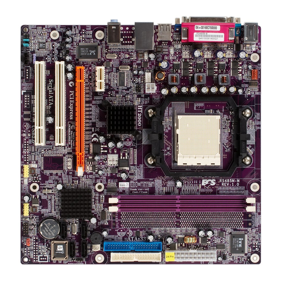
Motherboard Components Introducing the Motherboard... - Page 11 Table of Motherboard Components LABEL COMPONENT Socket AM2 for AMD Sempron/Athlon 64/ 1 CPU Socket Athlon 64 X2 Dual-Core/Athlon 64 FX proces- sors 2 DIMM1~2 240-pin DDR2 SDRAM slots 3 ATX_POWER Standard 24-pin ATX power connector 4 FDD Floppy diskette drive connector 5 IDE1 Primary IDE channel 6 PWR_FAN...
- Page 12 Memo Introducing the Motherboard...
-
Page 13: Installing The Motherboard
Chapter 2 Installing the Motherboard Safety Precautions • Follow these safety precautions when installing the motherboard • Wear a grounding strap attached to a grounded device to avoid damage from static electricity • Discharge static electricity by touching the metal case of a safely grounded object before working on the motherboard •... -
Page 14: Checking Jumper Settings
Do not over-tighten the screws as this can stress the motherboard. Checking Jumper Settings This section explains how to set jumpers for correct configuration of the motherboard. Setting Jumpers Use the motherboard jumpers to set system configuration options. Jumpers with more than one pin are numbered. -
Page 15: Checking Jumper Settings
Checking Jumper Settings The following illustration shows the location of the motherboard jumpers. Pin 1 is labeled. Jumper Settings Type Jumper Description Setting (default) 1-2: NORMAL CLR_CMOS 2-3: CMOS CLEAR CLR_CMOS 3-pin CLEAR CMOS Before clearing the CMOS, make sure to turn off the system. -
Page 16: Connecting Case Components
Connecting Case Components After you have installed the motherboard into a case, you can begin con- necting the motherboard components. Refer to the following: Connect the CPU cooling fan cable to CPU_FAN. Connect the system cooling fan connector to SYS_FAN. Connect the power fan connector to PWR_FAN. -
Page 17: Atx 24-Pin Power Connector
PWR_FAN: FAN Power Connector Signal Name Function System Ground Power +12V +12V Sense Sensor CPU_FAN/SYS_FAN: FAN Power Connectors Signal Name Function System Ground Power +12V +12V Sense Sensor CPU FAN control Users please note that the fan connector supports the CPU cooling fan of 1.1A~2.2A (26.4W max.) at +12V. -
Page 18: Front Panel Connector
Front Panel Connector The front panel connector (PANEL1) provides a standard set of switch and LED connec- tors commonly found on ATX or micro-ATX cases. Refer to the table below for informa- tion: Signal Function Signal Function HD_LED_P Hard disk LED(+) FP PWR/SLP *MSG LED(+) HD_LED_N Hard disk LED(-) FP PWR/SLP *MSG LED(-) -
Page 19: Installing Hardware
Installing Hardware Installing the Processor Caution: When installing a CPU heatsink and cooling fan make sure that you DO NOT scratch the motherboard or any of the surface-mount resistors with the clip of the cooling fan. If the clip of the cooling fan scrapes across the motherboard, you may cause serious damage to the motherboard or its components. -
Page 20: Cpu Installation Procedure
CPU Installation Procedure The following illustration shows CPU installation components. Install your CPU. Pull up the lever away from the socket and lift up to 90-degree angle. Locate the CPU cut edge (the corner with the pin hold noticeably missing). Align and insert the CPU correctly. -
Page 21: Installing Memory Modules
Installing Memory Modules This motherboard accommodates two memory modules. It can support two 240-pin unbuf- fered DIMM, DDR2 800/667/533/400. The maximum memory capacity is 16 GB. DDR2 SDRAM memory module table Memory module Memory Bus DDR2 400 200 MHz DDR2 533 266 MHz DDR2 667 333 MHz... - Page 22 Table A: Supported DDR2 QVL (Qualified Vendor List) Type Size Vendor Module Name Hynix HYMP532U646-E3 AA 256 MB NANYA NT256T64UH4A0F-5A DDR2 400 SAMSUNG M378T3253FG0-CCC Hynix HYMP564U648-E3 AA 512 MB SAMSUNG M378T6553BZO-CCC A-DATA M2OHY2F3G3110A1B0Z Elixir M2U25664TUH4A0F-37B Infineon HYS64T32000HU-3.7-A 256 MB Kingston KVR533D2N4 Ramaxel RML 1040M28D5F-533...
-
Page 23: Installing A Hard Disk Drive/Cd-Rom/Sata Hard Drive
Table B: Unbuffered DIMM Address Timings and Drive Strength for AM2 Packge DRAM DIMM1 DIMM2 Timing Mode Speed DDR2-400 DDR2-400 DDR2-533 SRx16 SRx16 DDR2-533 SRx16 SRx8 SRx8 SRx16 DDR2-533 SRx8 SRx8 DDR2-533 DRx8 DRx8 DDR2-533 DRx8 SRx16 SRx16 DRx8 DDR2-533 DRx8 SRx8 SRx8... -
Page 24: Installing A Floppy Diskette Drive
Refer to the illustration below for proper installation: Attach either cable end to the connector on the motherboard. Attach the other cable end to the SATA hard drive. Attach the SATA power cable to the SATA hard drive and connect the other end to the power supply. - Page 25 Installing Add-on Cards The slots on this motherboard are designed to hold expansion cards and connect them to the system bus. Expansion slots are a means of adding or enhancing the motherboard’s features and capabilities. With these efficient facilities, you can increase the motherboard’s capabili- ties by adding hardware that performs tasks that are not part of the basic system.
-
Page 26: Installing Add-On Cards
Follow these instructions to install an add-on card: Remove a blanking plate from the system case corresponding to the slot you are going to use. Install the edge connector of the add-on card into the expansion slot. Ensure that the edge connector is correctly seated in the slot. Secure the metal bracket of the card to the system case with a screw. - Page 27 Connecting Optional Devices Refer to the following for information on connecting the motherboard’s optional devices: AUDIO1: Front Panel Audio header (Optional) This header allows the user to install auxiliary front-oriented microphone and line-out ports for easier access. Signal Name Function FMICIN_L Left Front Microphone input signal AUD_GND...
-
Page 28: Connecting Optional Devices
USB3/4: Front Panel USB headers The motherboard has four USB ports installed on the rear edge I/O port array. Additionally, some computer cases have USB ports at the front of the case. If you have this kind of case, use auxiliary USB connector to connect the front-mounted ports to the motherboard. Signal Name Function USBPWR... - Page 29 CD_IN1: Analog audio input connector Signal Name Function CD In right channel CD in_R Ground Ground CD In left channel CD in_L SATA1/2/3/4: Serial ATA connectors These connectors are used to support the new Serial ATA devices for the highest date transfer rates (1.5 Gb/s), simpler disk drive cabling and easier PC assembly.
- Page 30 AUXIN1: Auxliary In connector (Optional) Signal Name Function AUX In right channel AUX_R Return Right Aux in RET_R Return Left Aux in RET_L AUX In left channel AUX_L WOL1: Wake On LAN Connector (Optional) If you haveinstalled a LAN card, use the cable provided with the card to plug into the motherboard WOL connector.
- Page 31 Connecting I/O Devices The backplane of the motherboard has the following I/O ports: PS2 Mouse Use the upper PS/2 port to connect a PS/2 pointing device. PS2 Keyboard Use the lower PS/2 port to connect a PS/2 keyboard. Parallel Port Use LPT to connect printers or other parallel communications (LPT) devices.
-
Page 32: Connecting I/O Devices
Installing the Motherboard... -
Page 33: Chapter 3 Using Bios
Chapter 3 Using BIOS About the Setup Utility The computer uses the latest Award BIOS with support for Windows Plug and Play. The CMOS chip on the motherboard contains the ROM setup instructions for configuring the motherboard BIOS. The BIOS (Basic Input and Output System) Setup Utility displays the system’s configura- tion status and provides you with options to set system parameters. -
Page 34: Bios Navigation Keys
Press DEL to enter SETUP Pressing the delete key accesses the BIOS Setup Utility: Phoenix-AwardBIOS CMOS Setup Utility: Standard CMOS Features Frequency/Voltage Control Advanced BIOS Features Load Fail-Safe Defaults Advanced Chipset Features Load Optimized Defaults Integrated Peripherals Set Supervisor Password Power Management Setup Set User Password PnP/PCI Configurations... -
Page 35: Updating The Bios
Updating the BIOS You can download and install updated BIOS for this motherboard from the manufacturer’s Web site. New BIOS provides support for new peripherals, improvements in performance, or fixes for known bugs. Install new BIOS as follows: If your motherboard has a BIOS protection jumper, change the setting to allow BIOS flashing. -
Page 36: Standard Cmos Features
Standard CMOS Features This option displays basic information about your system. Phoenix-AwardBIOS CMOS Setup Utility Standard CMOS Features Date (mm:dd:yy) Wed, Jan 25 2005 Item Help Time (hh:mm:ss) 9 : 33 : 26 Menu Level IDE Channel 0 Master [None] IDE Channel 0 Slave [None] Change the day, month,... - Page 37 If you are setting up a new hard disk drive that supports LBA mode, more than one line will appear in the parameter box. Choose the line that lists LBA for an LBA drive. IDE Channel 0/1 Master/Slave IDE/Extended IDE Drives (Auto) Leave this item at Auto to enable the system to automatically detect and configure IDE devices on the channel.
-
Page 38: Advanced Bios Features
Advanced BIOS Features This option defines advanced information about your system. Phoenix-AwardBIOS CMOS Setup Utility Advanced BIOS Features ATA 66/100 IDE Cable Msg [Enabled] Item Help CPU Feature [Press Enter] Menu Level Hard Disk Boot Priority [Press Enter] CPU Internal Cache [Enabled] External Cache [Enabled]... - Page 39 Hard Disk Boot Priority (Press Enter) Scroll to this item and press <Enter> to view the following screen: Phoenix-AwardBIOS CMOS Setup Utility Hard Disk Boot Priority 1.Bootable Add-in Cards Item Help Menu Level Use < > or < > to select a device, then press <+>...
-
Page 40: Advanced Chipset Features
Typematic Rate Setting (Disabled) If this item is enabled, you can use the following two items to set the typematic rate and the typematic delay settings for your keyboard. • Typematic Rate (Chars/Sec): Use this item to define how many characters per second are generated by a held-down key. -
Page 41: Dram Configuration
DRAM Configuration (Press Enter) Scroll to this item and press <Enter> to view the following screen: Phoenix-AwardBIOS CMOS Setup Utility DRAM Configuration Item Help Timing Mode [Auto] Memclock index value or Limi DDR2 400 Menu Level DQS Training Control [Skip DQS] CKE base power down mode [Enabled] CKE based powerdown [Per channel]... - Page 42 • (Twr) Write Recovery Time (3 bus clocks): Use this item to specify the Write to Read delay. • (Trtp) Precharge Time (3 clocks): Use this item to specify the Precharge Time. • (Trc) Row Cycle Time (26 bus clocks): Use this item to specify the Row Cycle Time.
-
Page 43: Integrated Peripherals
PCIE GFX Core Payload Size (64 Bytes) This item allows users to manually adjust the PCIE GFX Core Payload size. PCIE GPP Core Payload Size (64 Bytes) This item allows users to manually adjust the PCIE GPP Core Payload size. GFX0 Link Width (x16) This item allows users to manually set the GFX Link Width. - Page 44 South OnChip IDE Device (Press Enter) Scroll to this item and press <Enter> to view the following screen: Phoenix-AwardBIOS CMOS Setup Utility South OnChip IDE Device Item Help IDE DMA transfer access [Enabled] Onchip IDE Channel0 [Enabled] Menu Level IDE Prefetch Mode [Enabled] Primary Master PIO [Auto]...
- Page 45 South OnChip PCI Device (Press Enter) Scroll to this item and press <Enter> to view the following screen: Phoenix-AwardBIOS CMOS Setup Utility South OnChip PCI Device Item Help Onboard Azalia AUDIO [Auto] Onboard 1394 [Enabled] Menu Level Onboard PCI Lan [Enabled] Onboard Lan Boot ROM [Disabled]...
- Page 46 SuperIO Device (Press Enter) Scroll to this item and press <Enter> to view the following screen: Phoenix-AwardBIOS CMOS Setup Utility SuperIO Device Item Help Onboard FDC Controller [Enabled] Onboard Serial Port 1 [3F8/IRQ4] Menu Level Onboard Serial Port 2 [2F8/IRQ3] Onboard Parallel Port [378/IRQ7] Parallel Port Mode...
-
Page 47: Power Management Setup
Power Management Setup This option lets you control system power management. The system has various power- saving modes including powering down the hard disk, turning off the video, suspending to RAM, and software power down that allows the system to be automatically resumed by certain events. - Page 48 Resume Event Control (Press Enter) Scroll to this item and press <Enter> to view the following screen: Phoenix-AwardBIOS CMOS Setup Utility Resume Event Control Resume By Ring [Disabled] Item Help Resume By PCI PME [Enabled] Resume By PCI-E [Enabled] Menu Level Resume By USB (S3) [Disabled] Resume By PS/2 Mouse...
-
Page 49: Pnp/Pci Configurations
PNP/PCI Configurations These options configure how PnP (Plug and Play) and PCI expansion cards operate in your system. Both the the ISA and PCI buses on the motherboard use system IRQs (Interrup ReQuests) and DMAs (Direct Memory Access). You must set up the IRQ and DMA assignments correctly through the PnP/PCI Configurations Setup utility for the motherboard to work properly. -
Page 50: Pc Health Status
PC Health Status On motherboards that support hardware monitoring, this item lets you monitor the parameters for critical voltages, temperatures and fan speeds. Phoenix-AwardBIOS CMOS Setup Utility PC Health Status Item Help SMART Fan Function [Press Enter] Shutdown Temperature [Disabled] Menu Level Warning Temperature [Disabled]... -
Page 51: Frequency/Voltage Control
FAN1 Slope PWM value (0) Press Ctrl + F1 to show this item. This item specifies the slope PWM value of smart fan. Press <Esc> to return to the PC Health Status screen. Shutdown Temperature (Disabled) This item enables or disables you to set the maximum temperature the system can reach before powering down. -
Page 52: Load Fail-Safe Settings
Load Fail-Safe Defaults This option opens a dialog box that lets you install fail-safe defaults for all appropriate items in the Setup Utility: Press <Y> and the <Enter> to install the defaults. Press <N> and then <Enter> to not install the defaults. The fail-safe defaults place no great demands on the system and are generally stable. -
Page 53: Save & Exit Setup
Save & Exit Setup Highlight this item and press <Enter> to save the changes that you have made in the Setup Utility and exit the Setup Utility. When the Save and Exit dialog box appears, press <Y> to save and exit, or press <N> to return to the main menu. Exit Without Saving Highlight this item and press <Enter>... - Page 54 Using BIOS...
-
Page 55: Using The Motherboard Software
Chapter 4 Using the Motherboard Software About the Software CD-ROM The support software CD-ROM that is included in the motherboard package contains all the drivers and utility programs needed to properly run the bundled products. Below you can find a brief description of each software program, and the location for your motherboard version. -
Page 56: Running Setup
Setup Tab Setup Click the Setup button to run the software installation program. Select from the menu which software you want to install. Browse CD The Browse CD button is the standard Windows command that allows you to open Windows Explorer and show the contents of the support Before installing the software from Windows Explorer, look for a file named README.TXT, INSTALL.TXT or something similar. - Page 57 Click Next. The following screen appears: Check the box next to the items you want to install. The default options are recommended. Click Next run the Installation Wizard. An item installation screen appears: Follow the instructions on the screen to install the items. Drivers and software are automatically installed in sequence.
-
Page 58: Manual Installation
Manual Installation Insert the CD in the CD-ROM drive and locate the PATH.DOC file in the root directory. This file contains the information needed to locate the drivers for your motherboard. Look for the chipset and motherboard model; then browse to the directory and path to begin installing the drivers. -
Page 59: Multi-Language Translation
Caractéristiques Processeur Cette carte mère utilise un socket AM2 ayant les caractéristiques suivantes : • Peut recevoir les processeurs AMD Sempron/Athlon 64/Athlon 64 FX/ Athlon 64 X2 Dual-Core • Prend en charge des vitesses d’interface HyperTransport (HT) allant jusqu’à 2000MT/s La Technologie HyperTransport est une liaison point à... - Page 60 1394a FireWire (Optionnel) • Entièrement conforme avec provisions de IEEE Std 1394-1995 pour les bus série de hautes performances et IEEE Std 1394a-2000 • Deux ports de câble entièrement conforme IEEE Std 1394a-2000 à 400M bits/s LAN interne (Optionnel) Cette carte mère prend en charge les chipsets LAN suivants : •...
- Page 61 Feature Prozessor Dieses Mainboard verwendet einen AM2-Sockel mit den folgenden Eigenschaften: • Nimmt AMD Sempron/Athlon 64/Athlon 64 FX/Athlon 64 X2 Dual-Core Prozessoren auf • Unterstützt bis zu 2000MT/s HyperTransport (HT) Interface- Geschwindigkeiten HyperTransport Technologie ist ein Punkt-zu-Punkt Link zwischen zwei Geräten. Es ermöglicht integrierten Schaltkreisen einen Informationsaustausch mit wesentlich höherer Geschwindigkeit als bei gängigen Interconnect-Technologien.
- Page 62 1394a FireWire (Optional) • Vollständige Entsprechung zu den Vorschriften des IEEE Std 1394-1995 für den Hochleistungs-Serial-Bus und IEEE Std 1394a-2000 • Zwei vollständig IEEE Std 1394a-2000 konforme Kabelports bei 400M Bits/s Integriertes LAN (optional) Dieses Mainboard kann einen der folgenden LAN-Chipsätze unterstützen: •...
- Page 63 Caratteristiche Processore La scheda madre utilizza una presa AM2 pin che offre le seguenti caratteristiche: • Compatibilità con processori AMD Sempron/Athlon 64/Athlon 64 FX/ Athlon64 X2 Dual-Core • Supporto di velocità di interfaccia HyperTransport (HT) fino a 2000 MT/s La tecnologia HyperTransport consente il collegamento point-to-point fra due dispositivi e quindi un trasferimento di informazioni tra circuiti integrati molto più...
- Page 64 FireWire 1394a (Opzionale) • Conformità completa a disposizioni IEEE Std 1394-1995 per bus seriale a elevate prestazioni e IEEE Std 1394a-2000 • Due porte cable a 400M bit/s conformi a IEEE Std 1394a-2000 integrata (Opzionale) La scheda madre offre supporto per uno dei seguenti chipset LAN: •...
- Page 65 Característica Procesador Esta placa principal usa Socket AM2 que ofrece las sigtes. características: • Acomoda procesadores AMD Sempron/Athlon 64/Athlon 64 FX/Athlon 64 X2 Dual-Core • Soporta hasta las velocidades de interfaz 2000 MT/s HyperTransport (HT) La Tecnología HyperTransport es un vínculo punto a punto entre dos dispositivos, habilita circuitos integrados para intercambiar la información en velocidades más rápidas que las tecnologías de interconexión disponibles actualmente.
- Page 66 1394a FireWire (optativo) • Conformidad total con las provisiones de IEEE Std 1394-1995 para un bus serial de alto rendimiento y IEEE Std 1394a-2000 • Dos puertos de cable con conformidad total de IEEE Std 1394a-2000 en 400M bits/s LAN Abordo (optativo) Esta placa principal puede soportar uno de los sigtes.
- Page 67 Características Processador Esta motherboard usa Ficha AM2 que possui as seguintes características: • Acomoda processadores AMD Sempron/Athlon 64/Athlon 64 FX/Athlon 64 X2 Dual-Core • Suporta velocidades de interface de HyperTransport (HT) até 2000MT/s Tecnologia de HyperTransport Té um link ponto-a-ponto entre dois dispositivos, permite circuitos integrados para trocar informação a velocidades muito mais elevadas que as disponíveis actualmente em tecnologias de interconexão.
- Page 68 1394a FireWire (opcional) • compatível com provisões de IEEE Std 1394-1995 para um bus de série de elevada performance e IEEE Std 1394a-2000 • Duas portas para cabo totalmente compatíveis com IEEE Std 1394a-2000 a 400M bits/s Onboard LAN (opcional) Esta motherboard poderá...
- Page 69 機能 プロセッサ このマザーボードには、次の機能を持ったソケット AM2があります: • AMD Sempron/Athlon 64/Athlon 64 FX/Athlon 64 X2 Dual-Core プロ セッサの搭載に対応 • 転送率が最大2000MT/秒までの HyperTransport (HT)インターフェース を採用 HyperTransport 技術とは、二つのデバイスを1対1( point-to-point)で接続する技 術であり、従来のインターコネクト技術に比較して、集積回路同士の情報交換を高速化 します。 チップセット RS485 Northbridge (NB)と SB460 Southbridge (SB)チップセットは、実証された信 頼性と性能を持つ革新的で拡張性のあるアーキテクチャに基づいています。 RS485 (NB) • 1つの x2 ( x4に拡張可能) A-Link Express インターフェース (PCI Express 1.0a に対応)でATI IXPに接続...
- Page 70 1394a (オプション) • “IEEE Std 1394-1995 for a high-performance serial bus and IEEE Std 1394a-2000”の基準に完全対応 • IEEE Std 1394a-2000 完全対応の2つのポートのそれぞれが400M bits/秒 の転送率を実現 オンボードLAN (オプション) 当マザーボードは次のLANチップセットのいずれかを搭載しております: • 10/100Mb/s N-way自動ネゴシエーション操作をサポート • 半/全二重の機能をサポート • Wake-On-LAN(WOL)と遠隔wake-up機能をサポート • 10/100/1000 トランシーバーを搭載済み • PCI v2.3, 32-bit, 33/66-MHzへの対応 •...
- Page 71 특성 프로세서 본 마더보드에 탑재된 소켓 AM2는 다음과 같은 기능을 제공한다: • AMD 샘프론/애슬론 64/애슬론 64 FX/애슬론 64 X2 Dual-Core 프로세서 사용 • HyperTransport (HT) 인터페이스 속도 최대 2000MT/s 지원 HyperTransport 기술은 두 장치간의 point-to-point 링크로, 집적 회로가 기존의 상호 연결 기술 보다 더 빠른 속도로 정보를 교환할 수 있다. 칩셋...
- Page 72 1394a 파이어 와이어(선택 사항) • 고성능 시리얼 버스를 위한 IEEE Std 1394-1995 및 IEEE Std 1394a-2000 부 합 • 400M bits/s 속도로 케이블 포트에 부합하는 2 개의 IEEE Std 1394a-2000 보드 내장 LAN (선택 사항) 본 마더보드는 다음과 같은 LAN 칩셋을 지원합니다: •...
- Page 73 功能 處理器 此主機板使用具有如下特性的Socket AM2 插槽: • 可安裝AMD Sempron/Athlon 64/Athlon 64 FX/Athlon 64 X2 Dual-Core 處 理器 • 支援高達2000MT/秒的HyperTransport (HT)介面傳輸速率 HyperTransport 技術為以點對點方式連接兩台設備的技術,藉此,積體電路間能夠以 後高於現有各種內部連接技術(interconnect technology)技術的速度來交換資訊。 晶片組 RS485 北橋(NB)及SB460 南橋(SB)晶片組在研發設計上採用了創新且具擴充性之架構, 具備優良的可靠性及性能。 RS485 (NB) • 1個 2倍速 (可擴充至4倍速) A-Link Express介面 (PCI Express 1.0a 相容) 以連接ATI IXP •...
- Page 74 1394a FireWire (選購) • 完全支援"IEEE Std 1394-1995 for a high-performance serial bus 及 IEEE Std 1394a-2000" 規格 • 2個IEEE Std 1394a-2000連接埠,傳輸速率達400M bits/秒 內建區域網路 (選購) 本主機板搭載有如下其中一種LAN晶片組: • 支援 10/100Mb/s N-way 自動協調作業 • 支援半/全雙工功能 • 支援區域網路喚醒(Wake-On-LAN)及遠端喚醒功能 • 整合有10/100/1000 收發器 • 支援PCI v2.3, 32位元, 33/66-MHz •...
- Page 75 功能 处理器 主板使用一个 Socket AM2 插座,此插座具有以下特点: • 支持 AMD Sempron/Athlon 64/Athlon 64 FX/Athlon 64 X2 Dual-Core 处理 器 • 支持 2000 MT/s HyperTransport (HT) 接口速度 HyperTransport 技术是一种在两台设备间进行点到点连接的技术,它可以让集成电 路使用比当前互连技术更高的速度进行信息交换。 芯片组 RS485 北桥 (NB) 和 SB460 南桥 (SB) 芯片组是基于一种新型的、可扩展的架构,能 提供已经证明的可靠性和高性能。 RS485 (NB) •...
-
Page 76: Onboard Lan
1394a 火线(可选) • 完全符合用于高性能串行总线的 IEEE Std 1394-1995 和 IEEE Std 1394a- 2000 • 2 个符合 IEEE Std 1394a-2000 标准的电缆端口,传输速率可达 400M bits/s Onboard LAN(可选) 此主板支持以下任何一种 LAN 芯片组: • 支持 10/100Mb/s N 路自协商工作 • 支持半双工/全双工工作 • 支持 LAN 唤醒 (WOL) 功能和远程唤醒功能 • 集成... - Page 77 Характеристики Процессор Данная материнская плата размещает сокет AM2 и обладает следующими характеристиками: • Размещает процессоры AMD Sempron/Athlon 64/Athlon 64 FX/Athlon 64 X2 Dual-Core Поддерживает технологию 2000 MT/s HyperTransport (HT) • Технология HyperTransport обеспечивает связь двух устройств по протоколу point- to-point, позволяя гораздо более быстрый обмен информацией между интегральными микросхемами, чем...
- Page 78 1394a FireWire (опционально) • Полная совместимость с требованиями стандарта IEEE Std 1394-1995 для скоростных серийных шин и стандарта IEEE Std 1394a-2000 • Два кабельных порта, совместимых с IEEE Std 1394a-2000, со скоростью передачи 400M бит/с Встроенный сетевой адаптер LAN (опционально) Встроенный...
- Page 79 Cechy Procesor Ta płyta główna wyposażona jest w gniazdo AM2 i posiada następujące właściwości: • Obsługuje procesory firmy AMD typu Sempron/Athlon 64/Athlon 64 FX/ Athlon 64 X2 Dual-Core • Obsługuje złącze HyperTransport (HT) z szybkością do 2000MT/s Technologia HiperTransportu jest protokołem komunikacji między dwoma urządzeniami, który umożliwia układom zcalonym wymieniać...
- Page 80 1394a FireWire (opcjonalnie) • W pełni zgodna z zabezpieczeniem standardu IEEE 1394-1995 dla wysokiej wydajności szyny szeregowej oraz standardu IEEE 1394a-2000 • Dwa złącza całkowicie zgodne ze standardem IEEE 1394a-2000 o szybkości przesyłania 400M bits/s Zintegrowana obsługa sieci LAN (opcjonalnie) Zintegrowana obsługa sieci LAN posiada następujące właściwości: •...
- Page 81 Vlastnosti Procesor Tato základní deska využívá patici Socket AM2 nabízející následující vlastnosti: • Podpora procesorů AMD Sempron/Athlon 64/Athlon 64 FX/Athlon 64 X2 Dual-Core • Podpora rychlostí rozhraní HyperTransport (HT) až 2000 MT/s Technologie HyperTransport je přímým spojením mezi dvěma zařízeními, umožňující integrovaným obvodům výměnu informací...
- Page 82 1394a FireWire (volitelně) • Plná podpora standardu IEEE 1394–1995 pro vysokovýkonnou sériovou sběrnici a IEEE standard 1394a–2000 • Dva kabelové porty podle standardu IEEE 1394a–2000 s rychlostí až 400 Mb/s Vestavění síťové rozhraní LAN (volitelně) Vestavěné síťové rozhraní LAN nabízí následující možnosti: •...
- Page 83 Caracteristici Procesorul Această placă de bază suportă un socket AM2 care are următoarele caracteristici: • Funcţionează cu procesoare AMD Sempron/Athlon 64/Athlon 64 FX/ Athlon 64 X2 Dual-Core • Suportă interfeţe HyperTransport (HT) cu viteze de până la 2000 MT/s Tehnologia HyperTransport este o legătură...
- Page 84 1394a Fire Wire (opţional) • Compatibil deplin cu prevederile standardului IEEE 1394-1995, oferind un bus serial de înaltă performanţă şi compatibilitate cu standardul IEEE 1394a- 2000 • Două porturi de cablu compatibile deplin cu standardul IEEE 1394a-2000 , la viteza de 400 Mb/s Onboard LAN (opţional) Onboard LAN are următoarele caracteristici: •...
- Page 85 Спецификация Процесор Тази дънна платка използва сокет AM2 със следните спецификации: • Поддръжка на процесори AMD Sempron/Athlon 64/Athlon 64 FX/Athlon 64 X2 Dual-Core • Поддръжка на технологията HyperTransport (HT) със скорост до 2000MT/s Технологията HyperTransport е връзка точка-до-точка (point-to-point) между две...
- Page 86 1394a FireWire контролер (опция) • Пълна съвместимост със стандартите IEEE 1394 -1995 за високоскоростна серийна шина и IEEE 1394a -2000 • Два кабелни порта (400M bits/s) напълно съвместими със стандарта IEEE 1394a-2000 Интегриран мрежов контролер (опция) Спецификация на интегрирания мрежов контролер: •...
- Page 87 Jellemző Processzor Ez az alaplap az alábbi jellemzőkkel biró AM2 socket-el van ellátva: • AMD Sempron/Athlon 64/Athlon 64 FX/Athlon 64 X2 Dual-Core processzorokkal működik • Maximum 2000 MT/s HyperTransport (HT) sebességű interfészt támogat A HyperTransport technológia egy ponttól pontig való kapcsolat két készülék között, és segítségével az integrált áramkörök közötti információcsere sebessége sokkal nagyobb, mint a jelenleg rendelkezésre álló...
- Page 88 1394a FireWire (opcionális) • Teljesen kompatibilis az IEEE 1394-1995 szabvány elõírásaival, csúcsteljesítményű soros busszal, és megfelel az IEEE 1394a-2000 szabványnak • Két, az IEEE 1394a-2000 szabvánnyal teljesen kompatibilis kábelportok, 400 Mbit/s sebességen Alaplapon levő LAN (opcionális) Az alaplapon levő LAN jellemzői: •...
Need help?
Do you have a question about the RS485M-M and is the answer not in the manual?
Questions and answers