Table of Contents
Advertisement
Copyright
This publication, including all photographs, illustrations and software, is protected un-
der international copyright laws, with all rights reserved. Neither this manual, nor any
of the material contained herein, may be reproduced without w ritten consent of the au-
thor.
Version 5.1a
Disclaimer
The information in this document is subject to change without notice. The manufac-
turer makes no representations or warranties with respect to the contents hereof and
specifically disclaims any implied w arranties of merchantability or fitness for any par-
ticular purpose. The manufacturer reserves the right to revise this publication and to
make changes from time to time in the content hereof without obligation of the manu-
facturer to notify any person of such revision or changes.
Trademark Recognition
Microsoft, MS-DOS and Windows are registered trademarks of Microsoft Corp.
MMX, Pentium, Pentium-II, Pentium-III, Celeron are registered trademarks of Intel
Corporation.
Other product names used in this manual are the properties of their respective owners
and are acknowledged.
Federal Communications Commission (FCC)
This equipment has been tested and found to comply with the limits for a Class B digi -
tal device, pursuant to Part 15 of the FCC Rules. These limits are designed to provide
reasonable protection against harmful interference in a residential installation. This
equipment generates, uses, and can radiate radio frequency energy and, if not in-
stalled and used in accordance with the instructions, may cause harmful interference
to radio communications. However, there is no guarantee that interference will not oc-
cur in a particular installation. If this equipment does cause harmful interference to
radio or television reception, which can be determined by turning the equipment off
and on, the user is encouraged to try to correct the interference by one or more of the
following measures:
−
Reorient or relocate the receiving antenna.
−
Increase the separation between the equipment and the receiver.
−
Connect the equipment onto an outlet on a circuit different from that to which
the receiver is connected.
−
Consult the dealer or an experienced radio/TV technician for help.
Shielded interconnect cables and a shielded AC power cable must be employed with
this equipment to ensure compliance with the pertinent RF emission limits governing
this device. Changes or modifications not expressly approved by the system's manu-
facturer could void the user's authority to operate the equipment.
Preface
Advertisement
Table of Contents

Related Manuals for ECS P4S5A


Summary of Contents for ECS P4S5A
- Page 1 Preface Copyright This publication, including all photographs, illustrations and software, is protected un- der international copyright laws, with all rights reserved. Neither this manual, nor any of the material contained herein, may be reproduced without w ritten consent of the au- thor.
- Page 2 Declaration of Conformity This device complies with part 15 of the FCC rules. Operation is subject to the follow - ing conditions: − This device may not cause harmful interference, and − This device must accept any interference received, including interference that may cause undesired operation.
-
Page 3: Table Of Contents
Preface 錯誤! 尚未定義書籤。 Features and Packing List Translations CHAPTER 1 Introducing the Mainboard Introduction......................1 Checklist.........................1 Standard Items ....................1 Features........................2 Choosing a Computer Case................4 Mainboard Components..................5 CHAPTER 2 Installing the Mainboard Safety Precautions....................6 Quick Guide......................6 Installing the Mainb oard in a Case..............7 Checking Jumper Settings...................7 Setting Jumpers .................... - Page 4 Load Optimal Settings..................31 Load Best Performance Settings ..............31 Features Setup Page..................31 CPU PnP Setup Page..................33 Hardware Monitor Page .................. 34 Change Password .................... 35 Change or Remove the Password ..............35 Exit ........................35 CHAPTER 4 Using the Mainboard Software About the Software CD-ROM................36 Auto-installing under Windows 98..............36...
-
Page 5: Introducing The Mainboard
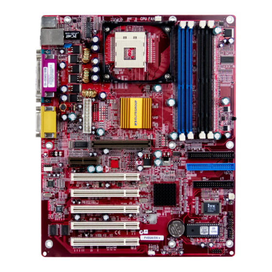
Introducing the Mainboard Congratulations on purchasing the P4S5A mainboard. This mainboard has a Socket-478 processor socket for Intel Pentium 4 type of processors support- ing front side bus (FSB) speeds up to 400/533 MHz. This mainboard integrates the SiS 645/SiS 645DX Northbridge along with... -
Page 6: Features
• The PGA Socket 478 Processor • Supports Intel Pentium 4 series CPUs • Supports up to 400/533 MHz Frontside Bus Note: SiS 645DX Northbridge supports up to 533MHz Frontside bus. Chipset The SiS 645/SiS 645DX and SiS961 chipsets are based on an innovative and scalable architecture with proven reliability and performance. - Page 7 • Power Supports RTC Alarm, Wake On Modem, AC97 Wake-Up Management and USB Wake-Up This mainboard includes a 4xAGP slot that provides four times the bandwidth of the original AGP specification. AGP technol- ogy provides a direct connection between the graphics sub- system and memory so that the graphics do not have to com- pete for processor time with other devices on the PCI bus.
-
Page 8: Choosing A Computer Case
The mainboard has a full set of I/O ports and connectors: Onboard I/O • Ports Two PS/2 ports for mouse and keyboard • Two serial ports • One parallel port • One MIDI/game port • Four USB ports (two backpanel ports, onboard USB headers providing two extra ports) •... -
Page 10: Installing The Mainboard
Installing the Mainboard Follow these safety precautions when installing the mainboard: • Wear a grounding strap attached to a grounded device to avoid damage from static electricity. • Discharge static electricity by touching the metal case of a safely grounded object before working on the mainboard. •... -
Page 11: Installing The Mainb Oard In A Case
Refer to the following illustration and instructions for installing the mainboard in a case: This illustration shows an ex- 2. Secure the mainboard with ample of a mainboard being screws where appropriate. installed in a tower-type case: Note: Do not overtighten the screws as this can stress the main- board. -
Page 12: Checking Jumper Settings
Checking Jumper Settings The following illustration shows the location of the mainboard jumpers. Pin 1 is labeled. Jumper Settings Jumper Type Description Setting (default) 3-pin Clear CMOS 1-2: Clear CMOS jumper 2-3: Normal 4-pin Onboard LAN 1-2: Link LED LED Jumper 3-4: LED Active JP4: Clear CMOS Jumper Use this jumper to clear the contents of the CMOS memory. -
Page 13: Connecting Case Components
JP3: Onboard LAN LED Jumper If you have a set indicator LEDs for the onboard LAN communication, you can connect the LED cable to the jumper JP3. Pins 1-2 are for LINK LED. Pins 3-4 are for 10/100 Mbps mode LED, the onboard LAN run in 100 Mbps mode when the LED lit. -
Page 14: Installing Hardware
This panel connector provides a set of switch and LED connectors found on ATX case. Refer to the table below for information. Device Pins Empty HDD LED Power/ACPI LED (Pin 1, 3) (Pin 2, 4) Power ON/OFF 6, 8 Reset Switch 5, 7 Power ACPI LED 2, 4... -
Page 15: Cpu Installation Procedure
manently damage the mainboard by generating excess heat in compo- nents that are run beyond the rated limits. This mainboard has a Socket 478 processor socket. When choosing a proc- essor, consider the performance requirements of the system. Performance is based on the processor design, the clock speed and system bus frequency of the processor, and the quantity of internal cache memory and external cache memory. - Page 16 Apply thermal grease to the top of the CPU. Swing the locking lever down and hook it under the latch on the edge of the socket. Snap the four retention legs of Cooling Fan the cooling fan into place. Heatsink Retention Module Swing both lock levers on top of the cooling fan to their opposite sides to se- cure the cooling fan on top of the heatsink.
-
Page 17: Installing Memory Modules
Installing Memory Modules This mainboard accommodates 168-pin 3.3V/184-pin 2.5V unbuffered SDRAM memory modules. The memory chips must be standard or registered SDRAM (Synchronous Dynamic Random Access Memory). The CPU supports 100MHz system bus. The SDRAM DIMMs and DDRs can synchronously work with 100 MHz or operates over a 333 MHz system bus. DDR SDRAM provides 800 MBps or 1 GBps data transfer depending on whether the bus is 100 MHz or 333 MHz. -
Page 18: Installing A Hard Disk Drive/Cd-Rom
Latch Latch Cutout Notch Cutouts Notches Latch Latch DDR SDRAM Module SDRAM Module Install the DIMM module into the slot and press it firmly down until it seats correctly. The slot latches are levered upwards and latch on to the edges of the DIMM. -
Page 19: Installing A Hard Disk Drive
Installing a Hard Disk Drive Install the hard disk drive into the drive cage in your system case. Plug the IDE cable into IDE1 (A): Note: Ribbon cable connectors are usually keyed so that they can only be installed correctly on the device connector. -
Page 20: Installing A Floppy Diskette Drive
Installing a Floppy Diskette Drive The mainboard has a floppy diskette drive (FDD) interface and ships with a diskette drive ribbon cable that supports one or two floppy diskette drives. You can install a 5.25-inch drive and a 3.5-inch drive with various capacities. The floppy diskette drive cable has one type of connector for a 5.25-inch drive and another type of connector for a 3.5-inch drive. -
Page 21: Installing Add-On Cards
Installing Add-on Cards This mainboard has five 32-bit PCI (Peripheral Components Interconnect) expansion slots, one 4xAGP slot, and one AMR slot. 4xAGP The 4xAGP slot is used to install a graphics adapter that supports the Slot 4xAGP specifications and has a 4xAGP edge connector. PCI Slots PCI slots are used to install expansion cards that have the 32-bit PCI interface. - Page 22 Follow these instructions to install an add-on card: Remove a blanking plate from the system case corresponding to the slot you are going to use. Install the edge connector of the add-on card into the expansion slot. Ensure that the edge con- nector is correctly seated in the slot.
-
Page 23: Connecting Optional Devices
Connecting Optional Devices Refer to the following for information on connecting the mainboard’s optional devices: AUDO1: Front panel MIC/Speaker Out header This header allows the user to install auxiliary front-oriented microphone and line-out ports for easier access. Signal Name Signal Name MICIN MIC-P 3 FPOUT-R 5... - Page 24 USB1: Front panel USB headers The mainboard has USB ports installed on the rear edge I/O port array. Some computer cases have a special module that mounts USB ports at the front of the case. If you have this kind of case, use auxiliary USB connectors USB1 to connect the front-mounted ports to the mainboard.
- Page 25 JP27/JP28/JP29: IEEE 1394 header This header will only exist when the mainboard incorporates the SiS962 Southbridge chipset. Use this header to connect to any IEEE 1394 interface. JP27 Signal Name Signal Name VCC_BUS TPB-0 TPB+0 TPA -0 TPA+0 Shield JP28 Signal Name Signal Name VCC_BUS...
-
Page 26: Connecting I/O Devices
The backplane of the mainboard has the following I/O ports: Parallel port (LPT1) Game port PS/2 port mouse PS/2 Serial port Serial port Microphone keyboard ports COM 1 COM 2 Line-in Line-out PS/2 Mouse Use the upper PS/2 port to connect a PS/2 point- ing device. -
Page 27: External Connector Color Coding
External Connector Color Coding Many connectors now use standard colors as shown in the table below. Connector Color Audio line-in Light blue Audio line-out Lime Digital monitor/flat panel White IEEE 1394 Grey Microphone Pink MIDI/game Gold Parallel Burgundy PS/2-compatible keyboard Purple PS/2-compatible mouse Green... -
Page 28: Using Bios
Using BIOS The computer uses the latest AMI BIOS with support for Windows Plug and Play. The CMOS chip on the mainboard contains the ROM setup instructions for configuring the mainboard BIOS. The BIOS (Basic Input and Output System) Setup Utility displays the system's configuration status and provides you with options to set system parameters. -
Page 29: Running The Setup Utility
Running the Setup Utility Each time your computer starts, before the operating system loads, a mes- sage appears on the screen that prompts you to “Hit <DEL> if you want to run SETUP”. When you see this message, press the Delete key and the Main menu page of the Setup Utility appears on your monitor. -
Page 30: Standard Cmos Features
to change the values for the option. Use the cursor arrow keys to scroll through the items in the submenu. In this manual, default values are enclosed in parenthesis. Submenu items are denoted by a triangle Standard CMOS Features Use this page to set basic information such as the date, the time, the IDE de- vices, and the diskette drives. -
Page 31: Advanced Bios Setup Option
Advanced BIOS Setup Option Use this page to set more advanced information about your system. Take some care with this page. Making changes can affect the operation of your computer. AMIBIOS SETUP – ADVANCED SETUP (C) 2000 American Megatrends, Inc. All Rights Reserved Quick Boot Enabled Boot Device... - Page 32 Floppy Drive Seek If you enable this item, your system will check all floppy disk drives at start up. Disable this item unless you are using an old 360KB drive. Password Check If you have entered a password for the system, use this item to determine, if the password is required to enter the Setup Utility (Setup) or required both at start-up and to enter the Setup Utility (Always).
-
Page 33: Power Management Setup Page
Power Management Setup Page This page sets some of the parameters for system power management opera- tion. AMIBIOS SETUP – POWER MANAGEMENT SETUP (C) 2000 American Megatrends, Inc. All Rights Reserved ACPI Aware O/S Power Management Enabled Suspend Time out Disabled Hard Disk Time out Disabled... -
Page 34: Pci / Plug And Play Setup
KeyBoard Power On If you enable this item, you can turn the system on and off by pressing hot keys on the keyboard. You must enable the Keyboard Power On jumper and use an ATX power supply in order to use this feature. PCI / Plug and Play Setup This page sets some of the parameters for devices installed on the PCI bus and devices that use the system plug and play capability. -
Page 35: Load Optimal Settings
Load Optimal Settings If you select this item and press Enter a dialog box appears. If you press Y, and then Enter, the Setup Utility loads a set of fail-safe default values. These default values are not very demanding and they should allow your system to function with most kinds of hardware and memory chips. - Page 36 Onboard Parallel Port Use this item to enable or disable the onboard LPT1 parallel port, and to as- sign a port address. The Auto setting will detect and available address. Parallel Port Mode Use this item to set the parallel port mode. You can select SPP (Standard Parallel Port), ECP (Extended Capabilities Port), EPP (Enhanced Parallel Port), or ECP + EPP.
-
Page 37: Cpu Pnp Setup Page
CPU PnP Setup Page This page lets you manually configure the mainboard for the CPU. The sys- tem will automatically detect the kind of CPU that you have installed and make the appropriate adjustments to the items on this page. AMIBIOS SETUP –... -
Page 38: Hardware Monitor Page
Hardware Monitor Page This page sets some of the parameters for the hardware monitoring function of this mainboard. AMIBIOS SETUP – HARDWARE MONITOR (C) 2000 American Megatrends, Inc. All Rights Reserved *** System Hardware *** Vcore 1.632V Vcc 2.5V/Vcc3.3V 2.496V Vcc 3.3V 3.392V 4.972V... -
Page 39: Change Password
Change Password If you highlight this item and press Enter, a dialog box appears which lets you enter a Supervisor password. You can enter no more than six letters or num- bers. Press Enter after you have typed in the password. A second dialog box asks you to retype the password for confirmation. -
Page 40: Using The Mainboard Software
Using the Mainboard Software The support software CD-ROM that is included in the mainboard package contains all the drivers and utility programs needed to properly run the bun- dled products. Below you can find a brief description of each software program, and the location for your mainboard version. -
Page 41: Running Setup
Setup Tab Setup Click the Setup button to run the software installation program. Select from the menu which software you want to install. Browse The Browse CD button is the standard Windows command that allows you to open Windows Explorer and show the contents of the support CD. - Page 42 Note: The following screens are examples only. The screens and driver lists will be different according to the mainboard you are installing. The mainboard identification is located in the upper left-hand corner. Click Next. The following screen appears: Check the items you want to install. The default options are recommended. Click Next to run the Installation Wizard.
-
Page 43: Manual Installation
Insert the CD in the CD-ROM drive and locate the PATH.DOC file in the root directory. This file contains the information needed to locate the drivers for your mainboard. Look for the chipset and mainboard model; then browse to the directory and path to begin installing the drivers. -
Page 44: Mediaring Talk - Telephony Software
MediaRing Talk – Telephony Software To install the MediaRing Talk voice modem software for the built-in modem, run MRTALK-SETUP72.EXE from the following directory: \UTILITY\MEDIARING TALK Super Voice – Fax/Modem Software To install the Super Voice voice, fax, data communication application for use with the built-in fax/modem, run PICSHELL.EXE from the following directory: \UTILITY\SUPER VOICE WinFlash Utility...