ECS Motherboard User Manual
Motherboard
Hide thumbs
Also See for Motherboard:
- User manual (97 pages) ,
- Manual (52 pages) ,
- User manual (65 pages)
Table of Contents
Advertisement
Quick Links
Advertisement
Table of Contents

Related Manuals for ECS Motherboard


Summary of Contents for ECS Motherboard
- Page 3 Preface Copyright This publication, including all photographs, illustrations and software, is protected under international copyright laws, with all rights reserved. Neither this manual, nor any of the material contained herein, may be reproduced without written consent of the author. Version 1.0 Disclaimer The information in this document is subject to change without notice.
-
Page 4: Declaration Of Conformity
Cet appareil numérique de la classe B respecte toutes les exigences du Réglement sur le matériel brouilieur du Canada. About the Manual The manual consists of the following: Chapter 1 Describes features of the motherboard. Introducing the Motherboard Go to page 1 Chapter 2 Describes installation of motherboard components. -
Page 5: Table Of Contents
Features....................2 Motherboard Components..............4 Chapter 2 7 7 7 7 7 Installing the Motherboard Safety Precautions................7 Choosing a Computer Case...............7 Installing the Motherboard in a Case..........7 Checking Jumper Settings..............8 Setting Jumpers................8 Checking Jumper Settings...............9 Jumper Settings................9 Connecting Case Components............10 ..............12 Front Panel Header Installing Hardware................13... - Page 6 Load Default Settings..............42 Supervisor Password..............42 User Password................43 Save & Exit Setup .................43 Exit Without Saving...............43 Chapter 4 45 45 45 45 Using the Motherboard Software About the Software CD-ROM............45 Auto-installing under Windows XP/Vista........45 Running Setup................46 Manual Installation................50 Utility Software Reference..............50...
-
Page 7: Introducing The Motherboard
Chapter 1 Introducing the Motherboard Introduction Thank you for choosing the A780VM-M3 motherboard. This motherboard is a high performance, enhanced function motherboard that supports socket for Phenom processor (socket AM2+)/Athlon 64 X2 Dual-Core/Athlon Sempron processors for high-end business or personal desktop markets. -
Page 8: Features
Feature Processor This motherboard uses a socket AM2+/AM2 that carries the following features: • Accommodates AMD Phenom processor (socket AM2+) AMD Athlon 64X2 Dual-Core/Athlon 64/Sempron™ processors • Supports HyperTransport (HT) 3.0 interface speeds HyperTransport Technology is a point-to-point link between two devices, it enables integrated circuits to exchange information at much higher speeds than currently available interconnect technologies. -
Page 9: Bios Firmware
One IDE connector supporting up to two IDE devices • Six 7-pin SATA connectors This motherboard supports Ultra DMA bus mastering with transfer rates of 133/ 100/66/33 MB/s. Integrated I/O The motherboard has a full set of I/O ports and connectors: •... -
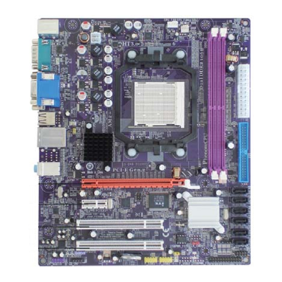
Page 10: Motherboard Components
Motherboard Components Introducing the Motherboard... - Page 11 20. PCIEX16 PCI Express x16 graphics card slot 21. USBPWR_R1 Rear Panel USB PS/2 Power Select Jumper 22. AT X12V 4-pin +12V power connector This concludes Chapter 1. The next chapter explains how to install the motherboard. Introducing the Motherboard...
- Page 12 Memo Introducing the Motherboard...
-
Page 13: Installing The Motherboard
I/O ports installed on the rear edge of the motherboard. This motherboard carries a Micro ATX form factor of 244 X 210 mm. Choose a case that accommodates this form factor. Installing the Motherboard in a Case Refer to the following illustration and instructions for installing the motherboard in a case. -
Page 14: Checking Jumper Settings
Do not over-tighten the screws as this can stress the motherboard. Checking Jumper Settings This section explains how to set jumpers for correct configuration of the motherboard. Setting Jumpers Use the motherboard jumpers to set system configuration options. Jumpers with more than one pin are numbered. -
Page 15: Checking Jumper Settings
Checking Jumper Settings The following illustration shows the location of the motherboard jumpers. Pin 1 is labeled. Jumper Settings Jumper Type Description Setting (default) 1-2: NORMAL 2-3: CLEAR CLR_CMOS 3-pin CLEAR CMOS Before clearing the CMOS, make sure to CLR_CMOS turn the system off. -
Page 16: Connecting Case Components
Connecting Case Components After you have installed the motherboard into a case, you can begin connecting the motherboard components. Refer to the following: Connect the CPU cooling fan cable to CPU_FAN. Connect the standard power supply connector to ATX_POWER. Connect the case speaker cable to SPK. -
Page 17: Atx 24-Pin Power Connector
Power +12V +12V Sense Sensor ATX_POWER: ATX 24-pin Power Connector Signal Name Signal Name +3.3V +3.3V +3.3V -12V Ground PS_ON Ground Ground PWRGD +5VSB +12V +12V +3.3V ATX12V: ATX 12V Power Connector Signal Name Ground Ground +12V +12V Installing the Motherboard... -
Page 18: Front Panel Header
SCSI (hard drive activity LED) connector. Power/Sleep/Message waiting LED Connecting pins 2 and 4 to a single or dual-color, front panel mounted LED provides power on/off, sleep, and message waiting indication. Installing the Motherboard... -
Page 19: Installing Hardware
You may be able to change these settings by making changes to jumpers on the motherboard, or changing the settings in the system Setup Utility. We strongly recommend that you do not over-clock processors or other components to run faster than their rated speed. -
Page 20: Cpu Installation Procedure
Plug the CPU fan power cable into the CPU fan connector (CPU_FAN) on the motherboard. To achieve better airflow rates and heat dissipation, we suggest that you use a high quality fan with 4800 rpm at least. CPU fan and heatsink installation procedures may vary with the type of CPU fan/heatsink supplied. -
Page 21: Installing Memory Modules
8 GB of memory; total memory capacity is 16 GB*. Do not remove any memory module from its antistatic packaging until you are ready to install it on the motherboard. Handle the modules only by their edges. Do not touch the components or metal parts. Always wear a grounding strap when you handle the modules. - Page 22 SRx16 DRx8 DRx8 SRx8 DDR2-667 SRx8 DRx8 DDR2-800 DDR2-800 1. SRx16=Single Rank x16 DIMM SRx8=Single Rank x8 DIMM DRx16=Dual Rank x16 DIMM DRx8=Dual Rank x8 DIMM The default value is unganged mode when using socket AM2+ CPU. Installing the Motherboard...
- Page 23 Table B: DDR2 (memory module) QVL (Qualified Vendor List) The following DDR2 1066 (AM2+)/800/667/533/400 memory modules have been tested and qualified for use with this motherboard. Type Size Vendor Module Name Samsung M378T 3354BZ0-CCC K4T51163QB-ZC CC 256 MB Samsung M378T6553BG0-CCC K4T51083QB-GCCC...
- Page 24 Due to the Phenom CPU and memory module limitation, the DRAM may need to adjust the voltage for supporting DDR2 1066. The memory modules which can be used stably are listed in the above QVL table for reference. Installing the Motherboard...
-
Page 25: Installing A Hard Disk Drive/Cd-Rom/Sata Hard Drive
1 of the I/O port connector. IDE: IDE Connector This motherboard supports six high data transfer SATA ports with each runs up to 3.0 Gb/s. To get better system performance, we recommend users connect the CD-ROM to the IDE channel, and set up the hard dives on the SATA ports. - Page 26 Refer to the illustration below for proper installation: Attach either cable end to the connector on the motherboard. Attach the other cable end to the SATA hard drive. Attach the SATA power cable to the SATA hard drive and connect the other end to the power supply.
-
Page 27: Installing Add-On Cards
Installing Add-on Cards The slots on this motherboard are designed to hold expansion cards and connect them to the system bus. Expansion slots are a means of adding or enhancing the motherboard’s features and capabilities. With these efficient facilities, you can in- crease the motherboard’s capabilities by adding hardware that performs tasks that are... - Page 28 Secure the metal bracket of the card to the system case with a screw. For some add-on cards, for example graphics adapters and network adapters, you have to install drivers and software before you can begin using the add-on card. Installing the Motherboard...
-
Page 29: Connecting Optional Devices
Connecting Optional Devices Refer to the following for information on connecting the motherboard’s optional devices: F_AUDIO: Front Panel Audio header This header allows the user to install auxiliary front-oriented microphone and line- out ports for easier access. Signal Name Signal Name... - Page 30 Ground F_USB1~2: Front Panel USB headers The motherboard has four USB ports installed on the rear edge I/O port array. Additionally, some computer cases have USB ports at the front of the case. If you have this kind of case, use auxiliary USB connector to connect the front-mounted ports to the motherboard.
- Page 31 IR: Infrared header The motherboard supports an Infrared (IR) data port. Infrared ports allow the wire- less exchange of information between your computer and similarly equipped devices such as printers, laptops, Personal Digital Assistants (PDAs), and other computers. Signal Name...
-
Page 32: Connecting I/O Devices
Connecting I/O Devices The backplane of the motherboard has the following I/O ports: PS2 Mouse Use the upper PS/2 port to connect a PS/2 pointing device. PS2 Keyboard Use the lower PS/2 port to connect a PS/2 keyboard. Serial Port... -
Page 33: Using Bios
About the Setup Utility The computer uses the latest “American Megatrends Inc. ” BIOS with support for Windows Plug and Play. The CMOS chip on the motherboard contains the ROM setup instructions for configuring the motherboard BIOS. The BIOS (Basic Input and Output System) Setup Utility displays the system’s configuration status and provides you with options to set system parameters. -
Page 34: Bios Navigation Keys
Press DEL to enter SETUP Press the delete key to access the BIOS Setup Utility. CMOS Setup Utility -- Copyright (C) 1985-2007, American Megatrends, Inc. Standard CMOS Setup Frequency/Voltage Control Advanced Setup Load Default Settings Advanced Chipset Setup Supervisor Password Integrated Peripherals User Password Power Management Setup... -
Page 35: Updating The Bios
Updating the BIOS You can download and install updated BIOS for this motherboard from the manufacturer’s Web site. New BIOS provides support for new peripherals, improve- ments in performance, or fixes for known bugs. Install new BIOS as follows: If your motherboard has a BIOS protection jumper, change the setting to allow BIOS flashing. -
Page 36: Standard Cmos Setup
Your computer has one IDE channel which can be installed with one or two devices (Master and Slave). In addition, this motherboard supports six SATA channels and each channel allows one SATA device to be installed. Use these items to configure each device on the IDE channel. - Page 37 Block (Multi-Sector Transfer (Auto) If the feature is enabled, it will enhance hard disk performance by reading or writing more data during each transfer. PIO Mode (Auto) Use this item to set the PIO mode to enhance hard disk performance by optimizing the hard disk timing.
-
Page 38: Advanced Setup
Advanced Setup This page sets up more advanced information about your system. Handle this page with caution. Any changes can affect the operation of your computer. CMOS Setup Utility - Copyright (C) 1985-2007, American Megatrends, Inc. Advanced Setup Help Item HT Frequency Auto CPU Virtualization... - Page 39 Use this item to determine the device order the computer used to look for an operating system to load at start-up time. The devices showed here will be different depending on the exact devices installed on your motherboard. Boot Other Device (Yes)
-
Page 40: Advanced Chipset Setup
Advanced Chipset Setup This page sets up more advanced information about your system. Handle this page with caution. Any changes can affect the operation of your computer. CMOS Setup Utility - Copyright (C) 1985-2007, American Megatrends, Inc. Advanced Chipset Setup Help Item DRAM Frequency Auto... -
Page 41: Integrated Peripherals
Share Memory Auto Detection (Enabled) Disable this item to set the Share Memory Size. And if the item is set to Auto, Share Memory Size can be controlled according to the dram size. When the dram size is less than 512 MB, Share Memory Size should be set to 64 MB. While between 512 MB and 1 GB, it should be set to 128 MB. - Page 42 OnBoard LAN Function (Enabled) Use this item to enable or disable the onboard LAN function. OnBoard LAN Boot ROM (Disabled) Use this item to enable or disable the booting from the onboard LAN or a network add-in card with a remote boot ROM installed. Serial Port1 Address (3F8/IRQ4) Use this item to enable or disable the onboard COM1/2 serial port, and to assign a port address.
-
Page 43: Power Management Setup
Power Management Setup This page sets up some parameters for system power management operation. CMOS Setup Utility - Copyright (C) 1985-2007, American Megatrends, Inc. Power Management Setup Help Item ACPI Suspend Type S3 (STR) Soft-off by PWR-BTTN Instant Off Select the ACPI PWRON After PWR-Fail Power Off state used for... -
Page 44: Pci/Pnp Setup
Resume By PS2 KB (S3) (Disabled) This item enables or disables you to allow keyboard activity to awaken the system from power saving mode. Resume By PS2 MS (S3) (Disabled) This item enables or disables you to allow mouse activity to awaken the system from power saving mode. -
Page 45: Pc Health Status
PC Health Status On motherboards support hardware monitoring, this item lets you monitor the parameters for critical voltages, temperatures and fan speeds. CMOS Setup Utility - Copyright (C) 1985-2007, American Megatrends, Inc. PC Health Status Help Item -=- System Hardware Monitor -=- Smart Fan Function Press Enter Shutdown Temperature... - Page 46 DeltaT1 (+3) This item specifies the range that controls CPU temperature and keeps it from going so high or so low when smart fan works. SMART Fan Slope PWM value (4 PWM value/°C) This item is used to set the Slope Select PWM of the smart fan. Press <Esc>...
-
Page 47: Frequency/Voltage Control
Frequency/Voltage Control This page enables you to set the clock speed and system bus for your system. The clock speed and system bus are determined by the kind of processor you have installed in your system. CMOS Setup Utility - Copyright (C) 1985-2007, American Megatrends, Inc. Frequency/Voltage Control Help item Auto Detect DIMM/PCI CIK... -
Page 48: Load Default Settings
Load Default Settings This option opens a dialog box to ask if you are sure to install optimized defaults or not. You select [OK], and then press <Enter>, the Setup Utility loads all default values; or select [Cancel], and then press <Enter>, the Setup Utility does not load default values. -
Page 49: User Password
If you have made settings that you do not want to save, use the “Exit Without Saving” item and select [OK] to discard any changes you have made. This concludes Chapter 3. Refer to the next chapter for information on the software supplied with the motherboard. Using BIOS... - Page 50 Memo Using BIOS...
-
Page 51: Using The Motherboard Software
Using the Motherboard Software About the Software CD-ROM The support software CD-ROM that is included in the motherboard package contains all the drivers and utility programs needed to properly run the bundled products. Below you can find a brief description of each software program, and the location for your motherboard version. -
Page 52: Running Setup
Displays the path for all software and drivers available on the CD. Running Setup Follow these instructions to install device drivers and software for the motherboard: Click Setup. The installation program begins: The following screens are examples only. The screens and driver lists will be different according to the motherboard you are installing. - Page 53 2. During the Windows Vista Driver Auto Setup Procedure, users should use one of the following two methods to install the driver after the system restart. Using the Motherboard Software...
- Page 54 Disable Vista UAC function before installing drivers, then use CD driver to install drivers, it will continue to install drivers after system restart without running blocked programs. Follow these instructions to Disable Vista UAC function: Go to Control Panel. Using the Motherboard Software...
- Page 55 Select Classic View. Set User Account. Select Turn User Account Control on or off and press Continue. Using the Motherboard Software...
-
Page 56: Manual Installation
This file contains the information needed to locate the drivers for your motherboard. Look for the chipset and motherboard model; then browse to the directory and path to begin installing the drivers. Most drivers have a setup program (SETUP.EXE) that automatically detects your operating system before installation.
Need help?
Do you have a question about the Motherboard and is the answer not in the manual?
Questions and answers