Table of Contents
Advertisement
Available languages
Available languages
Advertisement
Table of Contents

Related Manuals for ECS RC410-M2


Summary of Contents for ECS RC410-M2
- Page 3 Preface Copyright This publication, including all photographs, illustrations and software, is protected under international copyright laws, with all rights reserved. Neither this manual, nor any of the material contained herein, may be reproduced without written consent of the author. Version 1.0 Disclaimer The information in this document is subject to change without notice.
- Page 4 Declaration of Conformity This device complies with part 15 of the FCC rules. Operation is subject to the following conditions: • This device may not cause harmful interference, and • This device must accept any interference received, including interference that may cause undesired operation Canadian Department of Communications This class B digital apparatus meets all requirements of the Canadian Interference-causing Equipment Regulations.
-
Page 5: Table Of Contents
T T T T T ABLE OF CONTENTS ABLE OF CONTENTS ABLE OF CONTENTS ABLE OF CONTENTS ABLE OF CONTENTS Preface Chapter 1 Introducing the Motherboard Introduction....................1 Feature......................2 Motherboard Components................4 7 7 7 7 7 Chapter 2 Installing the Motherboard Safety Precautions..................7 Choosing a Computer Case...............7 Installing the Motherboard in a Case............7... - Page 6 Integrated Peripherals..............33 PNP/PCI Configurations.............34 Hardware Health Configuration..........35 Boot Configuration Features............36 Power Management Setup............38 BIOS Security Features..............39 Load Default Settings..............40 Load Failsafe Settings..............40 Discard Changes.................40 Save & Exit Setup.................40 Exit Without Saving..............40 Chapter 4 41 41 41 41 41 Using the Motherboard Software About the Software CD-ROM..............41 Auto-installing under Windows 98/ME/2000/XP........41 Running Setup................42...
-
Page 7: Introducing The Motherboard
SATA v1.0 compliant, supporting four SATA ports with maximum transfer rate up to 150 MB/s each. The RC410-M2 motherboard is equipped with advanced full set of I/O ports in the rear panel, including PS/2 mouse and keyboard connectors, COM1, LPT, VGA, four USB ports, one optional LAN port, one optional 1394a port (another 1394a header onboard), and audio jacks for microphone, line-in and 8-channel line-out. -
Page 8: Feature
Feature Processor The RC410-M2 uses an LGA775 type of Pentium 4 that carries the following features: • Accommodates Intel P4 Prescott and Pentium D processors • Supports Front Side Bus (FSB) speeds of 800/533/400 MHz • Supports “Hyper-Threading” technology CPU “Hyper-Threading”... - Page 9 Two 40-pin IDE connectors supporting up to 4 IDE devices • One floppy disk drive interface • Four 7-pin SATA connectors The RC410-M2 motherboard supports UltraDMA bus mastering with transfer rates of 133/100/66/33 MB/s. Integrated I/O The motherboard has a full set of I/O ports and connectors: •...
-
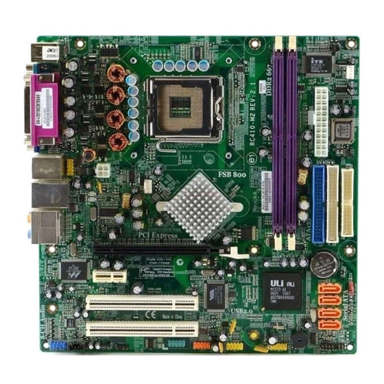
Page 10: Motherboard Components
Motherboard Components Introducing the Motherboard... - Page 11 Table of Motherboard Components LABEL COMPONENT 1 CPU Socket LGA775 socket for Pentium 4 CPUs 2 DIMM1~2 240-pin DDR2 SDRAM slots 3 IR1 Infrared header 4 CPU_FAN CPU cooling fan connector 5 ATX_POWER Standard 24-pin ATX power connector 6 BIOS_WP BIOS protection jumper 7 FDD Floppy diskette drive connector...
- Page 12 Memo Introducing the Motherboard...
-
Page 13: Installing The Motherboard
Make sure that your case supports all the features required. Secondly, RC410-M2 supports one or two floppy diskette drives and four enhanced IDE drives. Make sure that your case has sufficient power and space for all drives that you intend to install. -
Page 14: Checking Jumper Settings
Do not over-tighten the screws as this can stress the motherboard. Checking Jumper Settings This section explains how to set jumpers for correct configuration of the motherboard. Setting Jumpers Use the motherboard jumpers to set system configuration options. Jumpers with more than one pin are numbered. -
Page 15: Checking Jumper Settings
Checking Jumper Settings The following illustration shows the location of the motherboard jumpers. Pin 1 is labeled. Jumper Settings Type Jumper Description Setting (default) 1-2: NORMAL CLR_CMOS 2-3: CLEAR CMOS CLR_CMOS 3-pin CLEAR CMOS Before clearing the CMOS, make sure to turn off the system. -
Page 16: Connecting Case Components
Connecting Case Components After you have installed the motherboard into a case, you can begin con- necting the motherboard components. Refer to the following: Connect the CPU cooling fan cable to CPU_FAN. Connect the system cooling fan connector to SYS_FAN. Connect the case fan connector to CAS_FAN. - Page 17 CPU_FAN/SYS_FAN: FAN Power Connectors Signal Name Function System Ground Power +12V +12V Sense Sensor CPU FAN control Users please note that the fan connector supports the CPU cooling fan of 1.1A~2.2A (26.4W max) at +12V. CASE_FAN: FAN Power Connectors Signal Name Function System Ground Power +12V...
-
Page 18: Front Panel Connector
Front Panel Connector The front panel connector (PANEL1) provides a standard set of switch and LED connec- tors commonly found on ATX or micro-ATX cases. Refer to the table below for informa- tion: Signal Function Signal Function HD_LED_P Hard disk LED(+) FP PWR/SLP *MSG LED(+) HD_LED_N Hard disk LED(-) FP PWR/SLP *MSG LED(-) -
Page 19: Installing Hardware
Installing Hardware Installing the Processor Caution: When installing a CPU heatsink and cooling fan make sure that you DO NOT scratch the motherboard or any of the surface-mount resistors with the clip of the cooling fan. If the clip of the cooling fan scrapes across the motherboard, you may cause serious damage to the motherboard or its components. - Page 20 CPU Installation Procedure The following illustration shows CPU installation components. A. Unload the cap · Use thumb & forefinger to hold the lifting tab of the cap. · Lift the cap up and remove the cap completely from the socket. B.
-
Page 21: Installing Memory Modules
Installing Memory Modules This motherboard accomodates two memory modules. It can support two 240-pin 1.8V unbuffered DIMM, DDR2 400/533/667. The maximum memory capacity is 2GB. DDR2 SDRAM memory module table Memory module Memory Bus DDR2 400 200MHz DDR2 533 266MHz DDR2 667 333MHz You must install at least one module in any of the two slots. - Page 22 Table A: DDR2 QVL (Qualified Vender List) The following DDR2 memory modules have been tested and qualified for use with this motherboard. Type Size Vendor Model Name HYNIX HYMP532U646-E3 NANYA NT256T64UH4A0F-5A 256MB Samsung M378T3354BGO-CCC DDR2 400 Samsung M378T3354BZ0-CCC HYNIX HYMP564U648-E3 AA 512MB Infineon HYS64T64000HU-5-A...
-
Page 23: Installing A Hard Disk Drive/Cd-Rom/Sata Hard Drive
Installing a Hard Dish Drive/CD-ROM/SATA Hard Drive This section describes how to install IDE devices such as a hard disk drive and a CD-ROM drive. About IDE Devices Your motherboard has two IDE channel interfaces (IDE1 & IDE2). Two IDE ribbon cables supporting four IDE devices is bundled with the motherboard. - Page 24 About SATA Connectors This motherboard features four SATA connectors supporting a total of four drives. SATA , or Serial ATA (Advanced Technology Attachment) is the standard interface for the IDE hard drives which are currently used in most PCs. These connectors are well designed and will only fit in one orientation.
-
Page 25: Installing A Floppy Diskette Drive
Installing a Floppy Diskette Drive The motherboard has a floppy diskette drive (FDD) interface and ships with a diskette drive ribbon cable that supports one or two floppy diskette drives. You can install a 5.25-inch drive and a 3.5-inch drive with various capacities. The floppy diskette drive cable has one type of connector for a 5.25-inch drive and another type of connector for a 3.5-inch drive. -
Page 26: Installing Add-On Cards
Installing Add-on Cards The slots on this motherboard are designed to hold expansion cards and connect them to the system bus. Expansion slots are a means of adding or enhancing the motherboard’s features and capabilities. With these efficient facilities, you can increase the motherboard’s capabili- ties by adding hardware that performs tasks that are not part of the basic system. -
Page 27: Connecting Optional Devices
Follow these instructions to install an add-on card: Remove a blanking plate from the system case corresponding to the slot you are going to use. Install the edge connector of the add-on card into the expansion slot. Ensure that the edge connector is correctly seated in the slot. Secure the metal bracket of the card to the system case with a screw. - Page 28 AUDIO1: Front Panel Audio header This header allows the user to install auxiliary front-oriented microphone and line-out ports for easier access. Signal Name Signal Name Signal Name Function PORT-FL PORT-FR ACZ-DET PORT-ER AGND SENSE B PORT-EL SPDIFO1: SPDIF out header This is an optional header that provides an S/PDIF (Sony/Philips Digital Interface) output to digital multimedia device through optical fiber or coxial connector.
- Page 29 1394A2: Onboard IEEE 1394a headers (optional) Connect this header to any device with IEEE 1394a interface. Signal Name Signal Name Signal Name Function TPA+ TPA- TPB+ TPB- Cable-Power Cable-Power Key Pin USB3/4: Front Panel USB header The motherboard has four USB ports installed on the rear edge I/O port array. Additionally, there are two USB headers onboard.
-
Page 30: Connecting I/O Devices
Connecting I/O Devices The backplane of the motherboard has the following I/O ports: PS2 Mouse Use the upper PS/2 port to connect a PS/2 pointing device. PS2 Keyboard Use the lower PS/2 port to connect a PS/2 keyboard. Parallel Port Use LPT1 to connect printers or other parallel communications (LPT1) devices. -
Page 31: Using Bios
Chapter 3 Using BIOS About the Setup Utility The computer uses the latest American Megatrends BIOS with support for Windows Plug and Play. The CMOS chip on the motherboard contains the ROM setup instructions for configuring the motherboard BIOS. The BIOS (Basic Input and Output System) Setup Utility displays the system’s configura- tion status and provides you with options to set system parameters. - Page 32 Press DEL to enter SETUP Press the delete key to access the BIOS Setup Utility: CMOS Setup Utility -- Copyright (C) 1985-2004, American Megatrends, Inc. Standard BIOS Features Power Management Setup BIOS Security Features Advanced BIOS Features Advanced Chipset Features Load Default Settings Integrated Peripherals Load Failsafe Settings...
-
Page 33: Updating The Bios
Updating the BIOS You can download and install updated BIOS for this motherboard from the manufacturer’s Web site. New BIOS provides support for new peripherals, improvements in performance, or fixes for known bugs. Install new BIOS as follows: If your motherboard has a BIOS protection jumper, change the setting to allow BIOS flashing. -
Page 34: Standard Bios Features
Standard BIOS Features This option displays basic information about your system. CMOS Setup Utility - Copyright (C) 1985-2004, American Megatrends, Inc. Standard BIOS Features System Overview Help Item AMIBIOS Version : 08.00.11 Use [ENTER], [TAB] Build Date : 06/09/05 or [SHIFT-TAB] TO : 410S0629 select a field. -
Page 35: Advanced Bios Features
Advanced BIOS Features This option displays basic information about your system. CMOS Setup Utility - Copyright (C) 1985-2004, American Megatrends, Inc. Advanced BIOS Features Help Item Advanced Settings Warning: Setting wrong values in below sections may cause Options for CPU system to malfunction. - Page 36 CPU Hyper-Threading (Enabled) This item allows users to enable or disable the CPU Hyper-Threading function. Press <Esc> to return to the Advanced BIOS Features page. IDE Configuration (Press Enter) Scroll to this item and press <Enter> to view the following screen: CMOS Setup Utility - Copyright (C) 1985-2004, American Megatrends, Inc.
- Page 37 IDE Ultra DMA Mode (Enabled) Select this item to enable or disable the IDE Ultra DMA Mode. Press <Esc> to return to the Advanced BIOS Features page. Floppy Configuration (Press Enter) Scroll to this item and press <Enter> to view the following screen: CMOS Setup Utility - Copyright (C) 1985-2004, American Megatrends, Inc.
-
Page 38: Advanced Chipset Features
Advanced Chipset Features This page sets up some parameters for system graphics allocation. CMOS Setup Utility - Copyright (C) 1985-2004, American Megatrends, Inc. Advanced BIOS Features Help Item Boot Graphics Adapter Priori [PEG/IGD] UMA Frame Buffer Size [128MB] Select which graphics Surround View Function [Disabled] controller to use as the... -
Page 39: Integrated Peripherals
Integrated Peripherals This page sets up more Integrated Peripherals about your system. Handle this page with caution. Any changes can affect the operation of your computer. CMOS Setup Utility - Copyright (C) 1985-2004, American Megatrends, Inc. Integrated Peripherals Help Item Legacy USB Support [Enabled] USB 2.0 Support... -
Page 40: Pnp/Pci Configurations
Parallel Port Mode (ECP) This item allows users to manually set the Paralle Port Mode. ECP Mode DMA Channel (DMA3) This item allows users to manually set the DMA Channel for ECP Mode. Parallel Port IRQ (IRQ7) This item allows users to manually set the Paralle Port IRQ value. Press <Esc>... -
Page 41: Hardware Health Configuration
Hardware Health Configuration This page helps you set up some parameters for the hardware monitoring function of this motherboard. CMOS Setup Utility - Copyright (C) 1985-2004, American Megatrends, Inc. Hardware Health Configuration Hardware Health Configure Help Item H/W Health Function [Enabled] Enables Hardware Ambient Temperature... -
Page 42: Boot Configuration Features
Boot Configuration Features This option displays boot configuration information about your system. CMOS Setup Utility - Copyright (C) 1985-2004, American Megatrends, Inc. Boot Configuration Features Help Item Boot Settings Boot Settings Configuration [Press Enter] Configure Settings during System Boot. Boot Device Priority [Press Enter] Removable Drives [Press Enter]... - Page 43 Boot Device Priority (Press Enter) Scroll to this item and press <Enter> to view the following screen: CMOS Setup Utility - Copyright (C) 1985-2004, American Megatrends, Inc. Boot Device Priority Boot Device Priority Help Item First Boot Device [1st FLOPPY DRIVE] Specifies the boot se- quence from the available devices.
-
Page 44: Power Management Setup
Power Mangement Setup This page sets up some parameters for system power management operation. CMOS Setup Utility - Copyright (C) 1985-2004, American Megatrends, Inc. Power Management Setup Help Item ACPI function [Enabled] ACPI Suspend Type [S1 & S3 (STR)] Hard Disk Power Down Mode [Disabled] Enable / Disable Suspend Time Out... -
Page 45: Bios Security Features
Resume by Alarm (Disabled) When set to Enabled, additional fields become adjustable and you can set the date (day of the month), hour, minute and second to turn on your system. When set to 0 (zero) for the day of the month, the alarm will power on your system every day at the specified time. Press <Esc>... -
Page 46: Load Default Settings
Load Default Settings This option opens a dialog box that lets you install optimized defaults for all appropriate items in the Setup Utility. Press <OK> and then <Enter> to install the defaults. Press <Canel> and then <Enter> to not install the defaults. If you only want to install setup defaults for a specific option, select and display that option, and then press <F9>. -
Page 47: Using The Motherboard Software
Chapter 4 Using the Motherboard Software About the Software CD-ROM The support software CD-ROM that is included in the motherboard package contains all the drivers and utility programs needed to properly run the bundled products. Below you can find a brief description of each software program, and the location for your motherboard version. -
Page 48: Running Setup
Setup Tab Setup Click the Setup button to run the software installation program. Select from the menu which software you want to install. Browse CD The Browse CD button is the standard Windows command that allows you to open Windows Explorer and show the contents of the support Before installing the software from Windows Explorer, look for a file named README.TXT, INSTALL.TXT or something similar. - Page 49 Click Next. The following screen appears: Check the box next to the items you want to install. The default options are recommended. Click Next run the Installation Wizard. An item installation screen appears: Follow the instructions on the screen to install the items. Drivers and software are automatically installed in sequence.
-
Page 50: Manual Installation
Manual Installation Insert the CD in the CD-ROM drive and locate the PATH.DOC file in the root directory. This file contains the information needed to locate the drivers for your motherboard. Look for the chipset and motherboard model; then browse to the directory and path to begin installing the drivers. - Page 51 Caractéristiques Processeur La RC410-M2 utilise un type LGA775 de Pentium 4 présentant les fonctionnalités suivantes : • Peut recevoir les processeurs Intel P4 Prescott et Pentium D • Supporte les vitesses de Bus frontal (FSB) de 800/533/400 MHz • Prend en charge le CPU de technologie " Hyper-Threading"...
- Page 52 Une interface de lecteur de disquette • Quatre connecteurs SATA à 7 broches La RC410-M2 carte mère prenant en charge la maîtrise de bus UltraDMA avec vitesses de transfert de 133/100/66/33 Mo/s. E/S intégrées La carte mère possède un jeu complet de ports d’E/S et de connecteurs: •...
- Page 53 Feature Prozessor Das RC410-M2 verwendet einen Pentium 4 vom Typ LGA775 mit den folgenden Eigenschaften: • Unterstützt Intel P4 Prescott und Pentium D Prozessoren • Unterstützt Front Side Bus (FSB) Geschwindigkeiten von 800/533/400 • Unterstützt eine CPU mit „Hyper-Threading“ Technologie Bei der „Hyper-Threading”...
- Page 54 Zwei 40-Pin IDE Stecker, vier IDE-Kanäle unterstützen • Ein Steckplatz für ein Diskettenlaufwerk • Vier 7-Pin SATA-Stecker Die RC410-M2-Motherboard unterstützt UltraDMA Bus Mastering mit einer Übertragungsrate von 133/100/66/33 MB/Sek. Integrierte I/O-Schnittstellen Das Motherboard verfügt über einen kompletten Satz von I/O-Schnittstellen und Anschlüssen: •...
- Page 55 Caratteristiche Processore RC410-M2 si avvale di un tipo LGA775 di Pentium 4 che offre le seguenti caratteristiche: • Compatibile con processori Intel P4 Prescott e Pentium D • Supporto di FSB (Front Side Bus) con velocità pari a 800/533/400 MHz •...
- Page 56 Un’interfaccia per unità disco floppy • Quattro connettori SATA a 7 pin La scheda madre RC410-M2 supporta bus master UltraDMA con tasso di trasferimento di 133/100/66/33 MB/s. integrati La scheda madre offre una serie completa di porte e connettori I/O: •...
- Page 57 Característica Procesador La RC410-M2 usa un tipo LGA775 de Pentium 4 que tiene las sigtes. características: • Acomoda procesadores Intel P4 Prescott y Pentium D • Soporta las velocidades de Front Side Bus (FSB/Bus de Lado Frontal) de 800/533/400 MHz •...
- Page 58 Una interfaz de la unidad de disco floppy • Cuatro conectores SATA de 7-pin La placa principal RC410-M2 soporta el mastering de bus UltraDMA con índices de transferencia de 133/100/66/33 MB/s. I/O Integrado La placa principal tiene un juego completo de puertos y conectores I/O: •...
- Page 59 Características Processador O RC410-M2 utiliza um tipo LGA775 de Pentium 4 que possui as seguintes características: • Acomoda processadores Intel P4 Prescott e Pentium D • Suporta velocidades de Bus Frontal e Lateral (FSB) de 800/533/400 MHz • Suporta CPU de tecnologia “Hyper Threading”...
- Page 60 Um interface com drive de disco flexível • Quatro conectores SATA de 7 pin A motherboard RC410-M2 suporta um domínio bus UltraDMA bus com taxas de Transferência de 133/100/66/33 MB/s. I/O Integrado A motherboard possui um conjunto completo de portas I/O e conectores: •...
- Page 61 機能 プロセッサ RC410-M2 は次の特徴を有するLGA775 タイプのPentium 4を採用しています。 • IntelのP4 Prescott とPentium D プロセッサに対応 • 800/533/400 MHzのフロンサイドバス(FSB) を採用 • “ハイパースレッド” 技術をサポート ハイパースレッド(HT) 技術というのは、オペレーションシステムに2つのプロセッサが 存在すると認識させることで、実際には2つのスレッドを1つのプロセッサで同時に執行さ せ、平行利用を可能とする技術です。 チップセット RC410 Northbridge (NB)と M1573 Southbridge (SB)チップセットは、実証された信 頼性と性能を持つ革新的で拡張性のあるアーキテクチャに基づいています。 RC410 (NB) • 64ビット単一チャネル DDR/DDR2 SDRAM インターフェースを導入 • グラフィックインターフェースとなる PCI Express x16 インターフェース...
- Page 62 1394a (オプション) • “IEEE Std 1394-1995 for a high-performance serial bus and IEEE Std 1394a-2000”の基準に完全対応 • IEEE Std 1394a-2000 完全対応の2つのポートのそれぞれが400M bits/秒 の転送率を実現 オンボードLAN (オプション) 当マザーボードは次のLANチップセットのいずれかを搭載しております: • 10/100/1000 トランシーバーを搭載済み • PCI v2.3, 32-bit, 33/66-MHzへの対応 • IEEE 802.3z に完全対応 • Wake-On-LANと遠隔wake-up機能をサポート 拡張オプション 本マザーボードでは、次の拡張機能が利用できます。...
- Page 63 특성 프로세서 RC410-M2 는 팬티엄 4 의 LGA775 타입을 사용하며 다음과 같은 특성을 지닌다: • 인텔 P4 프레스콧 및 팬티엄 D 프로세서 사용. • Front Side Bus (FSB) 속도 800/533/400 MHz 지원 • "Hyper-Threading" 기술의 CPU 지원 "Hyper-Threading" 기술은 운영 체제가 두개의 프로세서에 연결되어 있는 것처럼, 두...
- Page 64 최대 4개의 IDE 장치를 지원하는 40핀IDE 커넥터 2 개 • 플로피 디스크 드라이브 인터페이스 1 개 • 7 핀 SATA 커넥터 4 개 RC410-M2 마더보드는 전송 속도 133/100/66/33 MB/s의 UltraDMA 버스 마스터링을 지원한다. 통합 I/O 본 마더보드는 풀 셋트의 I/O 포트 및 커넥터가 있다: •...
- Page 65 功能 處理器 RC410-M2 使用 LGA775 型的Pentium 4,具有如下功能: • 支援Intel P4 Prescott及Pentium D 處理器 • 支援800/533/400 MHz 的前端匯流排(FSB) • 支援使用超執行緒(Hyper-Threading)技術之CPU 利用“超執行緒(HT)”技術,可使作業系統在相當於裝上了兩具處理器的狀態下運 作:利用一個”實體”處理器模擬出兩個獨立的”邏輯”處理器,同時執行兩個工作 緒。 晶片組 RC410-M2 北橋(NB)及 M1573 南橋(SB)晶片組在研發設計上採用了創新且具擴充性之架 構,具備優良的可靠性及性能。 RC410 (NB) ‧ 64位元單通道DDR/DDR2 SDRAM介面 ‧ 支援1個繪圖介面用之PCI Express x16,完全符合PCI Express Base規格修訂版1.0a ‧...
- Page 66 1394a FireWire (選購) ‧ 完全支援"IEEE Std 1394-1995 for a high-performance serial bus 及IEEE Std 1394a- 2000" 規格 ‧ 2個IEEE Std 1394a-2000連接埠,傳輸速率達400M bits/秒 內建區域網路 (選購) 本主機板搭載有如下LAN功能: • 整合有10/100/1000 收發器 • 支援PCI v2.3, 32位元, 33/66-MHz • 完全支援IEEE 802.3z • 支援區域網路喚醒(Wake-On-LAN)及遠端喚醒功能 擴充選項 本主機板包括下列擴充選項: •...
- Page 67 功能 处理器 RC410-M2 主板使用 LGA775 型 Pentium 4 处理器,具有如下特点: • 支持 Intel P4 Prescott 和 Pentium D 处理器 • 支持 800/533/400 MHz 前端总线 (FSB) 速度 • 支持“多线程”技术 CPU “多线程”技术可以让操作系统认为自己连接了两个处理器,允许两个线程并行运 行,每个线程位于同一处理器中的单独“逻辑”处理器中。 芯片组 RC410 北桥 (NB) 和 M1573 南桥 (SB) 芯片组是基于一种新型的、可扩展的架构,能 提供已经证明的可靠性和高性能。...
- Page 68 2 个 32 位 PCI 扩展插槽 • 2 个 40-pin IDE 接口,可支持 4 个 IDE 设备 • 1 个软驱接口 • 4 个 7-pin SATA 接口 主板 RC410-M2支持 Ultra DMA 总线控制,传输速率可达 133/100/66/33MB/s。 集成 I/O 此主板具有完整的 I/O 端口和插孔: • 2 个用于连接鼠标和键盘的 PS/2 端口 • 1 个串口...
- Page 69 Характеристики Процессор Плата RC410-M2 использует процессор LGA775 типа Pentium 4 и обладает следующими характеристиками: • Размещает процессоры Intel P4 Prescott и Pentium D • Поддерживает шины Front Side Bus (FSB) со скоростью передачи данных 800/533/400 MГц • Поддерживает технологию CPU “Hyper-Threading”...
- Page 70 • Один разъем для накопителя на гибких дисках • Четыре разъема 7-pin SATA Плата RC410-M2 поддерживает технологию захвата управления шиной UltraDMA bus mastering со скоростью передачи данных 133/100/66/33 МБ/сек. Интегрированный вход/выход Плата снабжена полным набором портов входа/выхода и разъемов: •...
- Page 71 Cechy Procesor Płyta główna RC410-M2 zaopatrzona jest w procesor LGA775 typu Pentium 4 i posiada następujące właściwości: • Obsluguje procesory firmy Intel model P4 Prescott i Pentium D • Obsługuje główną szynę danych (FSB) z szybkościami 800/533/400 MHz • Zabezpiecza technologię CPU “Hyper-Threading”...
- Page 72 Dwa 40-nóżkowe złącza IDE mogące obsłużyć do czterech urządzeń IDE • Jedno złącze obsługujące stacje dyskietek • Cztery 7-nóżkowe złącza SATA Płyta główna RC410-M2 obsługuje szynę UltraDMA z szybkością transferu 133/100/66/33 MB/s. Zintegrowane We/Wy Płyta głwna wyposażona jest w pełny zestaw gniazd i złączy We/Wy: •...
- Page 73 Vlastnosti Procesor Základní deska RC410-M2 je určena pro procesory Pentium 4 LGA775 a může nabídnout následující vlastnosti: • Použití pro procesory Intel P4 s jádrem Prescott a Pentium D • Podpora taktování systémové sběrnice (FSB) na frekvenci 800/533/400 • Podporuje technologii CPU „Hyper-Threading“...
- Page 74 Dva 40kolíkový konektor IDE podporující až čtyři zařízení IDE • Jedno rozraní pro disketovou mechaniku • Čtyři 7kolíkové konektor SATA Základní deska RC410-M2 podporuje sběrnici Ultra DMA s přenosovými rychlostmi 133/100/66/33 MB/s. Integrovaný vstup/výstup Základní deska je vybavena kompletní sadou vstupních portů a konektorů I/O: •...
- Page 75 Caracteristici Procesorul RC410-M2 utilizează un procesor Pentium 4 de tip LGA775, având următoarele caracteristici: • Acomodează procesoare Intel P4 Prescott şi Pentium D • Suport viteză Front Side Bus (FSB) de 800/533/400 MHz • Este compatibilă cu unităţi centrale dotate cu tehnologia „Hyper- Threading”...
- Page 76 O interfaţă pentru unitate floppy • Patru conectoare SATA 7 Placa de bază RC410-M2 suportă bus mastering UltraDMA cu viteze de transfer de 133/100/66/33 MB/s I/O integrată Placa de bază este dotată cu un set complet de porturi şi conectoare I/O: •...
- Page 77 Спецификация Процесор RC410-M2 е предназначена за процесори LGA775 Pentium 4 със следните спецификации: • Поддръжка на процесори Intel P4 Prescott и Pentium D • Поддръжка на процесорна шина (FSB) на скорост 800/533/400 MHz • поддръжка на процесори с технология “Hyper-Threading"...
- Page 78 • един конектор за флопидисково устройство • четири 7-щифтови SATA конектораs Дънната платка RC410-M2 поддържа шина UltraDMA 133/100/66/33 MB/s Интегриран Вход/Изход контролер Дънната платка има пълен набор от I/O портове и конектори: • два PS/2 порта за мишка и клавиатура...
- Page 79 Jellemző Processzor Az RC410-M2 LGA775 típusú Pentium 4 számára készült, amely a következõ jellemzõkkel bír: • Intel P4 Prescott és Pentium D processzorok beépítését teszi lehetővé • Kompatibilis 800/533/400 MHz Front Side Bus (FSB) sebességekkel támogat • Támogatja a „Hyper-Threading” technológiát használó központi egységeket...
- Page 80 Két 40 tűs IDE csatlakozó négy IDE eszköz támogatására • Egy hajlékonylemez meghajtó interfész • Négy 7 tűs SATA csatlakozó A RC410-M2 alaplap támogatja az UltraDMA bus mastering megoldást, 133/100/66/33 MB/s sebességen Beépített I/O Az alaplapot az I/O portok és csatlakozók teljes készletével szerelték fel: •...
Need help?
Do you have a question about the RC410-M2 and is the answer not in the manual?
Questions and answers