Table of Contents
Advertisement
Advertisement
Table of Contents

Related Manuals for Ingrasys iPoMan II-1200


Summary of Contents for Ingrasys iPoMan II-1200
- Page 1 Power Distribution Unit (iPoMan II-1200)
-
Page 2: Preface
About this Manual Congratulations on purchasing the iPoMan II-1200. This user manual provides detailed descriptions of the hardware components and how to use the iPoMan II-1200. Read this manual carefully and follow the instructions while using the iPoMan II-1200. Copyright Information... -
Page 3: Safety Instructions
II-1200. • Use a standard power cord when connecting any device to the outlets of iPoMan II-1200. • The digital output only can connect switches, indicators, or other output devices that are normally open or normally closed. -
Page 4: Safety Notices
A drop or fall could cause injury.” D. “The equipment shall be installed according to specification as nameplate. Make sure the voltage of the power source when connect the equipment to the power outlet. The current of load and output iPoMan II-1200... - Page 5 E. “This equipment must be connected to the reliable earth before using.” iPoMan II-1200...
-
Page 6: Table Of Contents
Preface ................. 2 About this Manual..............2 Copyright Information ............2 Safety Instructions ..............3 Safety Notices ................. 4 Introduction the iPoMan II-1200......7 Features ................... 8 Package Contents ..............9 Hardware Components............10 Getting Started ............14 Attaching the Feet ..............14 Attaching the Ears.............. -
Page 7: Introduction The Ipoman Ii-1200
II-1200 comes with twelve power outlets, each of which can be monitored and controlled through the console or web interfaces. The iPoMan II-1200 is also equipped with a console port for connecting an EMD (Environmental Monitoring Device) for sensing temperature and humidity along with two alarms that can be activated when either of the sensors shows unusual values. -
Page 8: Features
• Administrator and multiple users with password protection for double-layer security • Address-specific security masks prevent unauthorized access • User-friendly interface to display input and output status • Upgrade utility for easy firmware upgrade • Available in 120V and 230V models iPoMan II-1200... -
Page 9: Package Contents
Package Contents Make sure the iPoMan II-1200 package has the following items. If any of items is missing or damaged, contact your nearest service center or vendor. 1. iPoMan II-1200 2. Ears (x2) 3. U-type handles (x2) 4. U-type handle screws (x4) 5. -
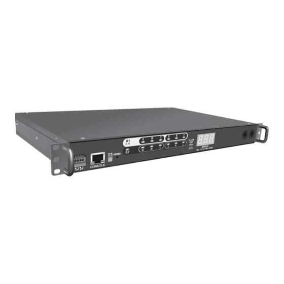
Page 10: Hardware Components
Hardware Components Take a moment to familiarize yourself with the iPoMan II-1200 front and rear panels. The following sections provide descriptions about the front and rear panel components and how to use them. Front Panel of 2-inlet Model Front Panel of 1-inlet Model... - Page 11 II-1200s is assigned by user manually. Please refer to DIP Switch Setting Table on page 21. 5. Reset button Enable you to reset the iPoMan II-1200 in case the system locks up. 6. Operation mode DIP Set the mode of operation for the iPoMan switch II-1200.
- Page 12 Status indicators The front panel of the iPoMan II-1200 has several LED indicators that provide information about the input and output power status. The following table describes these status indicators. Status indicator Description Input Output Display status of each power input and...
- Page 13 10 Amps for one unit or one outlet. 3. Daisy-chaining (C- Enable user to cascade next iPoMan II link ) port through an USB cable. 4. Ethernet (LAN) port Enable user to configure the iPoMan II- 1200 through a LAN or WAN iPoMan II-1200 ~13~...
-
Page 14: Getting Started
II-1200 as shown: Note: Users do not need to attach the feet if users are going to install the iPoMan II-1200 in a rack. Attaching the Ears The iPoMan II-1200 is designed to be placed in a rack arrangement... -
Page 15: Making Connections
Making Connections The iPoMan II-1200 is a versatile product that can be connected to several different types of input and output devices. This makes it a useful tool for connecting devices to it and controlling their power on/off status through its user interface. -
Page 16: Connecting Input Power
EMD to the console port. 2. To configure the iPoMan II-1200, users can use the console or LAN port. Connect the iPoMan II-1200 to a console and a LAN to enable its configuration through the console or browser menu. - Page 17 A through L with the power cords supplied with the devices as shown: Connecting Digital Outputs The iPoMan II-1200 provides two digital outputs to which users can connect switches, indicators, or other output devices that are normally open or normally close. Users can control the digital outputs remotely through the console or over the LAN/WAN.
-
Page 18: Connecting Emd
An Environmental Monitoring Device (EMD) that is connected to sensors for detecting temperature, humidity, water leak, and so on can be connected to the iPoMan II-1200 with the console port. The EMD can also be connected to alarms or indicators and controlled through the iPoMan II-1200. -
Page 19: Connecting The Console
Refer to Using the Console Menu on page 23 to learn how to use the console with a console application such as HyperTerminal or Telnet. Connecting to a LAN/WAN The iPoMan II-1200 has an RJ-45 LAN connection that enables users to monitor and manage the power outlets and digital outputs over the network. -
Page 20: Daisy Chaining
Follow instructions below to set up a daisy chained installation. 1. For each iPoMan II-1200 that you add to the chain, use USB cables to connect it to the parent iPoMan II-1200’s C-Link Port. - Page 21 Down: ON ; Up: OFF Manual mode: Use DIP switches on the front panel to set the (Daisy Chain) ID number for each iPoMan II-1200 that you add to the chain. You may set Daisy Chain ID for the first unit...
- Page 22 Note: The total length of all USB cables in the chain must not exceed 8 meters. The specification of USB cable is illustrated in following figure. All the iPoMan II-1200s and connected devices in the Daisy Chain can be controlled through Web Interface. iPoMan II-1200 ~22~...
-
Page 23: Using The Console Menu
Using the Console Menu The iPoMan II-1200 is provided with a serial port that enables users to configure and control the system through PC’s RS-232 serial (COM) port. Use the serial cable provided to connect the console port to PC’s COM port as described in Connecting the Console on page 19. - Page 24 “None”, Stop bits = “1” and Flow Control = “None”. Click OK when done. 5. Press any key. The iPoMan II-1200 Configuration Utility Main menu opens and users are prompted for a password. Type the default password (admin) and press Enter to continue.
-
Page 25: Navigating Through The Console Menu
• To select a submenu, type the number corresponding to the submenu and press Enter. For example, to select the iPoMan II-1200 Configuration menu, type 1 and press Enter. Submenus may have further nested menus which can also be accessed by typing the appropriate number. - Page 26 Email settings. This menu also provides the option under the control group submenu to enable input phase detection which allows the iPoMan II-1200 to turn off outlet power if there is a phase mismatch. • Outlets Control: Enables users to control all power outlets and configure each outlet’s name, location, and...
-
Page 27: Setting The Ip Address
II-1200 Configuration menu. 2. Select the IP Address item and set the IP address. This address lets users access the iPoMan II-1200 in a TCP/IP network (LAN/WAN). Contact the system administrator for assistance if users are not sure about what IP address to choose. -
Page 28: Using The Web Interface
Overview Start a web browser such as Internet Explorer from the host PC or laptop and enter the IP address of the iPoMan II-1200 in the address bar. For details about setting the IP address of the system, see Setting the IP Address on page 27. You will be prompted to enter a Username and Password. -
Page 29: Modifying The Basic Settings
1200 outlets and inputs status as described below: • The left pane shows the various menus and submenus for the iPoMan II-1200. Click any menu to display the menu options, expand the menu items, and modify the menu options as required. - Page 30 Changing Event Alert Settings The iPoMan II-1200 sends email or SNMP trap alerts to specified users when specific events occur. Use the following steps to set the alerts: • Click Trap Receivers...
-
Page 31: Modifying Application Settings
• Digital Output Status: This menu page shows the status of the both digital outputs and lets users specify which digital output is toggled when events occur. Users can also manually change the status of both digital outputs from this menu page. iPoMan II-1200 ~31~... - Page 32 Status Click Status under Environment menu to see the status of the EMD connected to the iPoMan II- 1200. menu page displays the temperature and humidity of the environment sensor, well open/close conditions of the EMD alarms. iPoMan II-1200 ~32~...
- Page 33 Delay field for each outlet in the Control webpage under Power Management as illustrated in the following figure. Similarly, to manage the Power-Off Sequence, set appropriate delay time in Power Off Delay field for each outlet in the same Control iPoMan II-1200 ~33~...
- Page 34 II-1200 ~34~...
-
Page 35: Appendix
2-inlet models of the The specifications for iPoMan II-1202( iPoMan II-1200) and -inlet models of the iPoMan II-1201(1 iPoMan II-1200) are listed as following: 2-inlet models of the iPoMan II-1200) iPoMan II-1202( Model iPoMan II -1202 -120V iPoMan II -1202 -230V... - Page 36 -inlet models of the iPoMan II-1200) iPoMan II-1201(1 Model iPoMan II -1201 -120V iPoMan II -1201 -230V IEC320 C20 inlet * 1pcs, IEC320 C20 inlet * 1pcs, Power Input 20Amps 16Amps Inlet-G1: 100-125VAC Inlet-G1: 200-240VAC 50/60Hz, 20A 50/60Hz, 16A Breaker Type &...
-
Page 37: Error Codes
Outlet I Current Over Threshold (Amp) Outlet J Current Over Threshold (Amp) Outlet K Current Over Threshold (Amp) Outlet L Current Over Threshold (Amp) Input Source Abnormal (Should be 120v Model) Input Source Abnormal (Should be 230v Model) iPoMan II-1200 ~37~... -
Page 38: Regulatory Information
Use only shielded cables to connect I/O devices to this equipment. Users are cautioned that changes or modifications not expressly approved by the party responsible for compliance could void the authority to operate the equipment. iPoMan II-1200 ~38~... - Page 39 CB and TUV The product is qualified per IEC 60950-1 and EN 60950-1, for the use in Information Technology Equipment, including Electric Business Equipment. The TUV Recognition or the CB certification is maintained for the product life. iPoMan II-1200 ~39~...
Need help?
Do you have a question about the iPoMan II-1200 and is the answer not in the manual?
Questions and answers