Table of Contents
Advertisement
Quick Links
Advertisement
Table of Contents

Related Manuals for Ingrasys iPoMan 8000

Summary of Contents for Ingrasys iPoMan 8000
- Page 1 8000 User Manual...
- Page 3 Preface About this manual Congratulations on purchasing the iPoMan 8000. This user manual provides detailed descriptions of the hardware components and how to use it. Read this manual carefully and follow the instructions while using the iPoMan 8000. Copyright information...
- Page 4 • Before plugging in the power cord of the device, make sure that the power source rating matches the power rating of the iPoMan 8000. • Use a standard power cord when you connect any device to the outlets of iPoMan 8000.
-
Page 5: Table Of Contents
Table of Contents Introducing the iPoMan 8000 Features ................. 2 Package contents ..............3 Hardware components............4 Front panel ..............4 Status indicators ............6 Using the control buttons ........7 Rear panel............... 9 Getting started Attaching the feet ..............10 Attaching the ears.............. - Page 6 Modifying application settings..........24 Setting control options ..........24 Setting up a schedule............ 25 Status ................25 Configuration ............... 25 Appendix Specifications ..............26 Error codes ................27 Regulatory information ............28 FCC Statement ............. 28 CE................. 29 UL ................29 iPoMan 8000...
-
Page 7: Introducing The Ipoman 8000
8000, manually or remotely, using a console or Ethernet connection. The iPoMan 8000 comes with eight power outlets, each of which, can be moni- tored and controlled through the console or web interfaces. You can also use the front panel to operate the power outlets. -
Page 8: Features
Device) inputs • Active extended devices via digital outputs • Monitor and manage connected devices and sensors remotely • Control the iPoMan 8000 manually, or remotely through console or network • Intelligent turn on/off devices based on event occurrence or planned schedule •... -
Page 9: Package Contents
Introducing the iPoMan 8000 Package contents Make sure that your package has the following items. If any of items is missing or damaged, contact your nearest service center or vendor. 1. iPoMan 8000 2. Ears (x2) 3. U-type handle (x2) 4. -
Page 10: Hardware Components
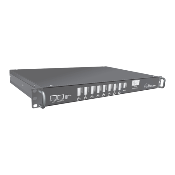
Introducing the iPoMan 8000 Hardware components Take a moment to familiarize yourself with the iPoMan 8000 front and rear panels. The following sections provide descriptions about the front and rear panel components and how to use them. Front panel Component... - Page 11 8000. S1 off, S2 off: Normal operation (default mode) Serial (CONSOLE) Enables you to configure the iPoMan 8000 port using the serial port. You can also connect an optional EMD to this port. Ethernet (LAN) port Enables you to configure the iPoMan 8000 through a LAN or WAN.
-
Page 12: Status Indicators
Introducing the iPoMan 8000 Status indicators The front panel of the iPoMan 8000 has several LED indicators that provide information about the input and output power status. The following table describes these status indicators. Status indicator Description Output power status indicator... -
Page 13: Using The Control Buttons
The control button has two modes of operation. Press the button repeatedly to switch between Remote Control mode and Power On/Off mode. When you press the control button, the iPoMan 8000 switches modes as follows: Original state Remote Control... - Page 14 Introducing the iPoMan 8000 Power on/off mode 1. Press the control button twice. The outlet power indicator starts flash- ing green. 2. Now press control button again within 5 seconds and hold for more than 5 seconds. The outlet power indicator starts flashing green at a faster speed and then inverts its original state.
-
Page 15: Rear Panel
Dry contact port Connect dry contact UPS that can be remotely managed through network card. This is cur- rently not supported by the iPoMan 8000. Digital output Connect up to digital outputs that are nor- mally open or normally closed. -
Page 16: Getting Started
Getting started This section provides information about setting up the iPoMan 8000, con- necting power, and connecting devices to it before you start using it for power management. Read this section carefully to learn how to connect var- ious devices to it. -
Page 17: Making Connections
Getting started Making connections The iPoMan 8000 is a versatile product that can be connected to several dif- ferent types of input and output devices. This makes it a useful tool for con- necting devices to it and controlling their power on/off status through its user interface. -
Page 18: Connecting Input Power
Getting started 2. To configure the iPoMan 8000, you can use the console or WAN port. Connect the iPoMan 8000 to a console and a WAN to enable its configuration through the console or browser menu. 3. After connecting to a console, use a console application such as Tel- net or HyperTerminal to access the console menu. -
Page 19: Connecting Output Devices
Getting started Connecting output devices The iPoMan 8000 has eight power outlets for connecting devices such as workstations, servers, and printers. Their power on/off status can be con- trolled manually as well as remotely through the LAN and Console ports. -
Page 20: Connecting Emd
An environmental monitored device that is connected to sensors for detect- ing temperature, humidity, water level, and so on can be connected to the iPoMan 8000 with the console port. The EMD can also be connected to alarms or indicators and controlled through the iPoMan 8000. Connect the... -
Page 21: Connecting The Console
PC, laptop, mobile phone, or PDA which is connected to the router net- work. Refer to “Using the web interface” on page 21 for details about how to con- trol the iPoMan 8000 and its output devices through the web. iPoMan 8000... -
Page 22: Using The Console Menu
Using the console menu The iPoMan 8000 is provided with a serial port that enables you to config- ure and control the system through your PC’s RS-232 serial (COM) port. Use the serial cable provided to connect the console port to your PC’s COM port as described in “Connecting the console”... - Page 23 Using the console menu 3. From the Connect using drop-down box, select the COM port that you have connected to the iPoMan 8000. Click OK when done. 4. The Properties window opens. Click Restore Defaults to use the default settings. Make sure that the Bits per second field is set to 9600.
-
Page 24: Navigating Through The Console Menu
Date option by typing 4 from the System Group and press Enter. Then type the date in the specified format (dd:mm:yyyy) and press Enter to save the changes. • Type 0 (zero) to return to a previous or higher-level menu. iPoMan 8000... - Page 25 Email settings. This menu also provides the option under the con- trol group submenu to enable input phase detection which allows the iPoMan 8000 to turn off outlet power if there is a phase mismatch. • Outlets Control: This enables you to control all power outlets and configure each outlet’s name, location, and other parameters.
-
Page 26: Setting The Ip Address
Using the console menu Setting the IP address Follow these steps to set up the IP address of the iPoMan 8000: 1. Using the steps described under “Navigating through the console menu” on page 18, navigate to the System Group under the iPoMan Configuration menu. -
Page 27: Using The Web Interface
Start a web browser such as Internet Explorer from your host PC or laptop and enter the IP address of the iPoMan 8000 in the address bar. For details about setting the IP address of the system, see “Setting the IP address” on page 20. -
Page 28: Modifying The Basic Settings
Using the web interface The main page shows a graphic representation of the iPoMan 8000 outlets and inputs status as described below: • The left pane shows the various menus and submenus for the iPoMan 8000. Click any menu to display the menu options, expand the menu items, and modify the menu options as required. -
Page 29: Adding Users
Edit or Delete for the appropriate user in the list. Changing event alert settings The iPoMan 8000 sends email or SNMP trap alerts to specified users when specific events occur. Use the following steps to set up these alerts: •... -
Page 30: Modifying Application Settings
• Inlet: Specify what action is taken by the iPoMan 8000 when the inlet voltage is not within limits. You can set which power outlets and digital outputs are to be turned on or off when the inlet voltage is not of acceptable value. -
Page 31: Setting Up A Schedule
Configuration Click Configuration under Environment to configure the EMD connected to the iPoMan 8000. This menu enables you to set up the sensor names, high and low set points, calibration offsets for the sensors, as well as alarm names and normal conditions. -
Page 32: Appendix
Appendix Specifications Power Input/Output iPoMan 8000 – 110V • AC Input: IEC C20 inlet, 15 Amp, 100 ~ 125VAC, model 50/60Hz • AC Output: NEMA 5-15R outlet, 15 Amp, 100 ~ 125 VAC, 50/60Hz • Load: 15 Amp for each outlet iPoMan 8000 –... -
Page 33: Error Codes
Input current sensor value abnormal Input source phase incorrect (see note below) Note: iPoMan 8000 detects the phase of the input source automatically. If the phase is opposite to that of the outlet phase, the outlet is turned off. The corresponding error code is displayed on the input power status indicator on the front panel with the error code and a message is displayed in a pop-window from your browser. -
Page 34: Regulatory Information
It is essential that only the supplied power cord be used. Use only shielded cables to connect I/O devices to this equipment. You are cautioned that changes or modifications not expressly approved by the party responsible for compliance could void your authority to operate the equipment. iPoMan 8000... - Page 35 CAN/CSA C22.2 No.950-M95 Third Edition, for the use in Infor- mation Technology Equipment, including Electric Business Equipment. The UL Recognition or the CSA certification is maintained for the product life. The UL and C-UL recognition mark or CSA monogram for CSA certifica- tion appears on the drive. iPoMan 8000...
Need help?
Do you have a question about the iPoMan 8000 and is the answer not in the manual?
Questions and answers