Table of Contents
Advertisement
Quick Links
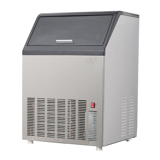
Má q in a Automá tica p ara Hacer Hiel o
User's Manual (
Man ual d el usario (
Be sure ice maker is stan d in g up rig h t 24 h ours p rior to p l ug -in
Aseg ú rese q ue l a má q uin a esté p arad e en p osició n v ertical 24 h oras an tes q ue sea
Automatic Ice Maker
con ectad a.
)
p ag es 1 -28
p á g in as 29 a 5 8
)
Mod el s/ Mod el os
EW CIM6 5 S
EW CIM9 0 S
EW CIM1 20 S
Advertisement
Table of Contents

Related Manuals for NORPOLE EW CIM65S


Summary of Contents for NORPOLE EW CIM65S
- Page 1 Automatic Ice Maker Má q in a Automá tica p ara Hacer Hiel o User’s Manual ( p ag es 1 -28 Man ual d el usario ( p á g in as 29 a 5 8 Be sure ice maker is stan d in g up rig h t 24 h ours p rior to p l ug -in Aseg ú...
-
Page 3: Ice Maker Safety
ICE MAKER S AFETY Your safety and the safety of others are very important. We have provided many important safety messages in this manual and on your appliance. Always read and obey all safety messages. This is the Safety Alert Symbol. This symbol alerts you to potential hazards that can injure or kill you and others. - Page 4 • • • • • • • • • • •...
- Page 5 • The ice maker should not be located next to ovens, grills or other sources of high heat. • The ice maker must be installed with all electrical, water and drain connections in accordance with state and local codes. A standard electrical supply ( 1 1 5 VAC only, 6 0 Hz, 1 5 A) , properly grounded in accordance with the National Electrical Code and local codes and ordinances is required.
-
Page 8: Component Locations
COMPONENT LOCATIONS Top cover Door Ice cube full sensor Right side Front cover Water sump Ice storage bin Ventilation louvers Ice scoop Leveling caster Control box P ower switch ( behind front cover) -
Page 9: Ice Maker Ins Tallation
ICE MAKER INS TALLATION Unpacking Ex cessiv e W eig h t Haz ard Use two or more people to move and install ice maker. Failure to do so can result in back or other injury. Remov e p ackag in g material s I MPORT ANT : Do not remove any permanent instruction labels or the data label on your ice maker. - Page 10 • To ensure proper ventilation for your ice maker, the front of the unit must be completely unobstructed. Allow at least 1 0 1 mm ( 4”) clearance at rear, and 1 5 mm ( 0 .6 ”) at top and sides for proper air circulation. The installation should allow the ice maker to be pulled forward for servicing if necessary.
-
Page 11: Electrical Requirements
• A standard electrical supply ( 1 1 5 VAC only, 6 0 Hz, 1 5 A) , properly grounded in accordance with the National Electrical Code and local codes and ordinances is required. • IMP ORTANT: Do not kink or pinch the power supply cord between the ice maker and wall or cabinet. -
Page 12: Water Supply And Drain Connections
Lev el ing th e I ce M aker It is important for the ice maker to be leveled in order to work properly. It can be raised or lowered by rotating the plastic sheaths around each of the four rolling casters on the bottom of the machine. - Page 14 I nstal l ation Ty pes This ice maker has been designed for Mobile ( free-standing) installation. It can also be Enclosed ( as under a cabinet) or Built-in ( sealed to the floor) , although this last option is not the preferred method of installation.
-
Page 15: Final Ch Eck List B Ef Ore Operation
5 . If the electrical outlet for the ice maker is behind the cabinet, plug in the ice maker. 6 . P ush the ice maker into position. 7 . Seal all around the cabinet to the floor with an approved caulking compound. OPERATION Final Ch eck List b ef ore Operation 1 . -
Page 16: Operating Method
Operating M eth od 1 . Switch on the P ower switch on the right side panel. The light will be on. The ice maker will start working automatically and feeding water. 2 . After the first feeding of the water, the machine will automatically go to the ice making stage, and the sound of water spraying will be heard. - Page 17 Harv est: During the harvest cycle the compressor is still operating, but the water pump has stopped. Two other components have been energized: the hot gas valve and the water inlet valve. These two valves open and warm up the freezing surface, allowing the cubes to fall into the bin.
-
Page 18: Preparing The Icemaker For Long Storage
• Water running from the water sump to the evaporator plate may make a splashing sound. • Water running from the evaporator to the water sump may make a splashing sound. • As each cycle ends, you may hear a gurgling sound due to the refrigerant flowing in your ice maker. -
Page 19: Cleaning And Maintenance
CLEANING AND MAINTENANCE If the ice maker is left unused for a long time, before the next use it must be thoroughly cleaned. Follow carefully any instructions provided for cleaning or use of sanitizing solution. Do not leave any solution inside the ice maker after cleaning. P eriodic cleaning and proper maintenance will ensure efficiency, top performance, and long life. -
Page 20: Condenser Cleaning
Stainless steel can discolor when exposed to chlorine gas and should be cleaned. Clean stainless steel with a mild detergent and warm water solution and a damp cloth. Never use abrasive cleaning agents. NOTI CE: S tainless steel exposed to chlorine gas and moisture, such as in areas with spas or swimming pools, may show some discoloration. -
Page 21: Interior Cleaning
I nterior Cl eaning The ice storage bin should be sanitized occasionally. Clean the bin before the ice maker is used for the first time and reused after stopping for an extended period of time. It is usually convenient to sanitize the bin after the ice making system has been cleaned and the storage bin is empty. - Page 22 2 . Take out the row of flake covers by snapping one end up and pulling forward. 3 . Remove the slideway from the water sump. 4. Find the sprinkler arm and raise it. Disconnect it from the water tube which is connected at the back of the sprinkler arm.
- Page 23 6 . Wipe down the interior of the water sump with the de-scaling solution and warm water. Rinse thoroughly with clear water. 7 . Reassemble the sprinkler arm, slideway and row of flake covers. 8 . P erform steps 1 , 3 , 6 , 7 and 8 of the Ice Making System Cleaning procedure below. I ce M aking S y stem Cl eaning Minerals that are removed from water during the freezing cycle will eventually...
- Page 24 5 . Allow 3 0 minutes for proper cleaning. After cleaning, shut off the power switch, and unscrew the nut of the water-draining hole on the rear of the unit. Drain off the waste water to some container, and then screw the nut on tightly when the waste water is fully drained off.
-
Page 25: Control Box
Control Box ( behind front cover) Red LED Clean Ice full Green LED Ice size adjust Yellow LED making Mode harvest Descrip tion s of LEDs an d b utton s: 1 . Red LED: Ice Full indicator light. When this LED is lit, the ice storage bin is full of ice or there is something between the two arms of the ice-full sensor in the ice storage bin. -
Page 26: Major Functions
3 . Yel l ow LED: Ice Harvest indicator light. When this LED is lit, the unit is working in the Ice Harvest mode controlled by a temperature probe on the evaporator. When the yellow LED is flashing, the unit is working in the Ice Harvest mode controlled by a fixed timer. -
Page 27: Troubleshooting
TROUBLES HOOTING Bef ore Cal l ing f or S erv ice If the unit appears to be malfunctioning, read through the OP ERATION section of this manual first. If the problem persists, check the TROUBLESHOOTING GUIDE below and on the following page. The problem could be something very simple which can be solved without a service call. - Page 28 Prob l em Possib l e Cause Prob ab l e Correction A few water drops fall to Normal condensation on the door or the floor when you open the some water together with ice. Take door to take out ice from care when you take out ice.
-
Page 29: Limited Warranty
LIMITED WARRANTY MC Appliance Corporation war r ant s ea c h new Commer c i al I c e Mak ert o be f r ee f r o m def e c t s i n mat er i al and workmanship and agrees to remedy any such defect or to furnish a new part(s) (at the company’s option) for any part(s) of the unit that has failed during the warranty period.
Need help?
Do you have a question about the EW CIM65S and is the answer not in the manual?
Questions and answers