Table of Contents
Advertisement
Advertisement
Table of Contents

Related Manuals for Jet XACTA Saw Deluxe


Summary of Contents for Jet XACTA Saw Deluxe
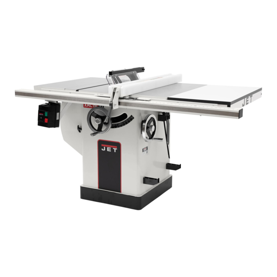
- Page 1 This .pdf document is bookmarked Operating Instructions and Parts Manual ® XACTA Saw Deluxe WALTER MEIER (Manufacturing) Inc. 427 New Sanford Road LaVergne, Tennessee 37086 Part No. M-708674 Ph.: 800-274-6848 Revision D 09/2013 www.waltermeier.com Copyright © 2013 Walter Meier (Manufacturing) Inc.
-
Page 2: Warranty And Service
Walter Meier is consistently adding new products to the line. For complete, up-to-date product information, check with your local Walter Meier distributor, or visit waltermeier.com. WARRANTY JET products carry a limited warranty which varies in duration based upon the product (MW = Metalworking, WW = Woodworking). WHAT IS COVERED? This warranty covers any defects in workmanship or materials subject to the exceptions stated below. -
Page 3: Table Of Contents
Table of Contents Warranty and Service ..........................2 Table of Contents ............................ 3 Warnings ..............................4 Introduction ............................. 6 Specifications ............................6 Shipping Contents ........................... 7 Unpacking ............................7 Cleaning .............................. 7 ... -
Page 4: Warnings
Warnings 1. Read and understand the entire owner's manual before attempting assembly or operation. 2. Read and understand the warnings posted on the machine and in this manual. Failure to comply with all of these warnings may cause serious injury. 3. - Page 5 19. Keep visitors a safe distance from the work area. Keep children away. 20. Make your workshop child proof with padlocks, master switches or by removing safety keys. 21. Give your work undivided attention. Looking around, carrying on a conversation and “horse-play” are careless acts that can result in serious injury.
-
Page 6: Introduction
Now that you have purchased a table saw, it is a good time to consider a dust collection system. See your local JET distributor for the complete line of dust collectors and the full line of JET Dust Collector Hoses and Accessories. -
Page 7: Shipping Contents
Read and understand the entire contents of this manual before attempting assembly or operation! Failure to comply may cause serious injury. Shipping Contents Unpacking Remove box and wood crating completely from around saw. Check for shipping damage. Report any damage immediately to your distributor and shipping agent. -
Page 8: Contents Of The Shipping Container
Contents of the Shipping Container Small Box Main Saw Container The small box consists of the following items: Table Saw (A) Switch (B) Blade Guard Assembly (E) Table Insert (C) Riving Knife and Pawl Assembly (F) Owner's Manual (D) Handwheel and Swivel Handle (G) Warranty Card (not shown) Lock Knob (H) Large Hook (J) -
Page 9: Assembly
Assembly Motor Cover Referring to Figures 1 and 2: • Tools: 17mm Wrench, 12mm Wrench 1. Remove shipping bracket (A) securing the motor (C) to table. 2. After the shipping bracket has been removed, install the screw (B) back into the motor support bracket. -
Page 10: Extension Wing
Extension Wing Referring to Figures 4 and 5: • Hardware: (6) 7/16”x1-1/2” Hex Cap Bolts, (6) 7/16” Lock Washers, (6) 7/16” Flat Washers & (2) Extension Wings • Tools: 17mm Wrench, Straight Edge 1. Attach the left extension wing (A) to the table (B) with three each hex cap screws (E), lock washers (F) and flat washers (G). -
Page 11: Riving Knife And Guard Installation
Riving Knife and Guard Installation Description Referring to Figure 7: The complete riving knife and guard assembly is shown in A. Before installing onto the saw, the anti- kickback pawl (E) must be separated from the riving knife (H) as follows: 1. -
Page 12: Mounting Rails & Extension Table
(available through your 7. Align the switch and tighten all hardware. authorized JET distributor or by calling Walter Meier (Manufacturing) Inc., at the number on the cover). Confirm power at the site is the same as the saw before making electrical connections. -
Page 13: Adjustments
Adjustments Handwheel Adjustments Referring to Figure 10: The front handwheel (B) controls the raising and lowering of the blade (blade height). The side handwheel (D) controls the blade tilt. The blade can be adjusted for a tilt between 90º (vertical or a setting of 0º on the scale) and 45º left tilt (D). -
Page 14: Riving Knife Adjustment
Riving Knife Adjustment Lateral alignment The saw blade and riving knife must be in line as close as possible with each other (lateral alignment) for the prevention of kickback. Upon initial blade guard and riving knife installation no further adjustment should be necessary. Alignment should be checked and adjusted, if required, after each blade change. -
Page 15: Blade Alignment
Blade Alignment • Tools: 8mm hex wrench, combination square, marker Blade alignment with the table is adjusted at the factory. After a period of use, or, after moving the saw to another location, the blade may no longer be aligned with the table. To check and align the blade (refer to Figure 16): 1. -
Page 16: Changing The Belt
5. If blade is not at 90 degrees, open the motor cover door, loosen lock nut (A, Fig. 19) and turn adjusting stop screw (B, Fig. 19) on the front trunnion in, or out. The adjusting stop screw should stop against the front trunnion bracket when the blade is 90°... -
Page 17: Maintenance
Maintenance Always disconnect power to the machine before performing maintenance. Failure to do this may result in serious personal injury. Cleaning Lubrication Note: The following maintenance schedule Grease the tilting worm gear, raising worm assumes the saw is being used every day. gear, castor system worm gear and the trunnion areas with a good grade non- Daily:... -
Page 18: Troubleshooting
Troubleshooting Trouble Possible Cause Solution Overload tripped Allow motor to cool and reset by pushing off switch Saw stops or will Saw unplugged from wall or motor Check all plug connections not start Fuse blown or circuit breaker tripped Replace fuse or reset circuit breaker Cord damaged Replace cord Stops not adjusted correctly... -
Page 19: Optional Accessories
Optional Accessories Stock No Description 708295 Tenoning Jig for 10” saws only: 708097 Dado Insert 708118 Universal Mobile Base Parts Ordering Replacement Parts Replacement parts are listed on the following pages. To order parts or reach our service department, call 1-800-274-6848, Monday through Friday (see our website for business hours, www.waltermeier.com). -
Page 20: Table & Cabinet Parts List
....JTAS10-33A ....Power Cord Sleeve (708676,708680) ....Ø22 ......1 34 ..... JTAS10L-34 .....Tilt Scale ....................1 35 ..... JTAS10-35 ....Warning Label ..................1 36 ..... JTAS10-36 ....JET Label ....................1 38 ..... JTAS10L-38WN ..Cabinet....................1 39 ..... TS-1482101 .....Hex Cap Screw ..........M6x50 ......1 40 ..... - Page 21 47 ..... TS-0210011 .....Socket Head Cap Screw ........7/16-14x3/4 ....4 48 ..... TS-0680011 .....Flat Washer ............3/16 ......2 49 ..... JTAS10L-49WN ..Lower Panel ..................1 50 ..... JTAS10L-50N ..Dust Hose Adapter ................1 51 ..... JTAS10-52W ...Switch Brace Kit ** ................1 52 .....
- Page 22 12 6 (optional) 18 6 20 (6) 28(2) 60(6) 20 (4) 47 4 28(4) 58(6) 56(6) 57(6) 55(2) 66(2) 65(2) 64(2)
-
Page 23: Trunnion & Motor Parts List
Trunnion & Motor Parts List Index No. Part No. Description Size 101 ... JTAS10L-101 ...Arbor Nut ....................1 102 ... JTAS10-102 .....Arbor Flange ..................1 104 ... JTAS10L-104N ..Arbor with Flange .................. 1 105 ... JTAS10-105 .....Key ..............M5x44 ......2 106 ... - Page 24 Trunnion & Motor Parts List Index No. Part No. Description Size 149 ... TS-0208041 .....Socket Head Cap Screw ........5/16-18x3/4” ....4 150 ... JTAS10L-150N ..Dust Deflector..................1 151 ... JTAS10L-151N ..Hose Clamp ..................2 152 ... JTAS10DX-152 ..Front Trunnion ..................1 ....
-
Page 25: Trunnion & Motor Assembly Drawing
Trunnion & Motor Assembly Drawing... -
Page 26: Blade Guard Parts And Assembly
Blade Guard Parts and Assembly Index No. Part No. Description Size 1 ....JTAS10L-301 ...Riving Knife ..................1 ....JTAS10DX-BGA ..Blade Guard Assembly (Index #2 thru #16, #21, #22) ......1 2 ....PM2000-302 ....Bushing ....................2 3 ....JTAS10L-303 ...Blade Guard Body ................. 1 4 .... -
Page 27: Wiring Diagrams
Wiring Diagrams 3HP/5HP, 230V, 1Phase... - Page 28 5HP, 230V, 3 Phase...
- Page 29 WALTER MEIER (Manufacturing) Inc. 427 New Sanford Road LaVergne, TN 37086 Phone: 800-274-6848 www.waltermeier.com...
Need help?
Do you have a question about the XACTA Saw Deluxe and is the answer not in the manual?
Questions and answers