Toa F-2000B Operating Instrucctions
Hide thumbs
Also See for F-2000B:
- Specifications (2 pages) ,
- Operating instructions manual (20 pages) ,
- Brochure & specs (4 pages)
Table of Contents
Advertisement
Quick Links
Advertisement
Table of Contents

Related Manuals for Toa F-2000B


Summary of Contents for Toa F-2000B
- Page 1 OPERATING INSTRUCTIONS SPEAKER SYSTEMS F-2000B F-2000W F-2000BT F-2000WT F-2000BTWP F-2000WTWP Thank you for purchasing TOA's Speaker System. Please carefully follow the instructions in this manual to ensure long, trouble-free use of your equipment. 533-06-146-2D...
-
Page 2: Table Of Contents
................4 5. IMPEDANCE CHANGE (F-2000BT, F-2000BTWP, F-2000WT, and F-2000WTWP only)....... 5 6. ABOUT THE INPUT OVERLOAD PROTECTION CIRCUITRY (F-2000B, F-2000W, F-2000BT, and F-2000WT only)..........5 7. NOTES ON OUTDOOR INSTALLATION (F-2000BTWP and F-2000WTWP only)..............6 8. INSTALLATION 8.1. Using the Supplied Brackets 8.1.1. -
Page 3: Safety Precautions
• Do not place heavy objects on the unit as this may cause it to fall or break which may result in • (F-2000B, F-2000BT, F-2000W, and F-2000WT personal injury and/or property damage. In only) addition, the object itself may fall off and cause Since the unit is designed for in-door use, do not injury and/or damage. -
Page 4: General Description
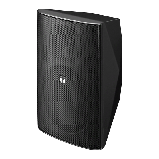
2. GENERAL DESCRIPTION TOA's F-2000 Series Speakers are compact two-way speaker systems designed for high efficiency, wide range, and high power input handling capability. These speaker systems can be installed in a manner ideal for the location and intended application. -
Page 5: Impedance Change
Failure to follow this instruction could result in damage to the speaker or amplifier. 6. ABOUT THE INPUT OVERLOAD PROTECTION CIRCUITRY (F-2000B, F-2000W, F-2000BT, and F-2000WT only) The speaker system features internal input overload protection circuitry for both high and low frequencies. -
Page 6: Notes On Outdoor Installation
7. NOTES ON OUTDOOR INSTALLATION (F-2000BTWP and F-2000WTWP only) • Be sure to mount the speaker in a vertical (portrait-style) orientation. • Adjust the speaker's tilt angle within the shaded range shown below: [Wall and pole: 0º horizontal to 45º downward] [Under eaves: 15º... -
Page 7: Installation
8. INSTALLATION 8.1. Using the Supplied Brackets The speaker system is supplied with the following brackets. Use these brackets properly depending on the installation location and intended application. [Speaker bracket] [Joint bracket] [Wall bracket] 30º 8.1.1. When using only the supplied brackets Installation Application Speaker bracket... -
Page 8: Wall Mounting
8.3. Wall Mounting When adjusting horizontal and vertical angles: Use the supplied wall bracket, joint bracket, and speaker bracket to permit adjustment of the horizontal and vertical* speaker coverage angles. * Vertical installation. Horizontal: Max. 70º, Vertical: Max. 45º downward Horizontal installation. - Page 9 Step 2. Attach the joint bracket to the wall bracket using the supplied screws, adjust the horizontal speaker angle, then tighten the screws. Note: Match the orientation of the arrows on both the wall bracket and joint bracket. Step 3. Attach the speaker bracket to the speaker's rear using the supplied screws. Note: Attach the speaker bracket according to the speaker mounting orientation.
-
Page 10: Ceiling Mounting
8.4. Ceiling Mounting Vertical orientation Use the supplied joint bracket and speaker bracket. Note Speaker coverage angles can only be adjusted in the vertical direction (Max. 45º downward). Adjust the speaker's tilt angle within the shaded range shown below: [Installation example] [Speaker angle vs. - Page 11 The mating surfaces of the speaker bracket and joint bracket are designed to interlock. Ensure that both parts are securely engaged with each other after mounting is complete. Horizontal orientation (F-2000B, F-2000BT, F-2000W, and F-2000WT only) [Installation example] Use the supplied joint bracket and speaker bracket in combination with the optional HY-CM20B or HY-CM20W Ceiling Mount Bracket.
-
Page 12: Speaker Stand Mounting
8.5. Speaker Stand Mounting The speaker can be mounted on the optional ST-16A Speaker Stand using the supplied joint bracket and speaker bracket. [Installation example] Speaker unit A s h o l e s e a l s a r e adhered over the holes, remove them using a p o i n t e d t o o l b e f o r e... -
Page 13: Pole Mounting (F-2000Btwp And F-2000Wtwp Only)
8.6. Pole Mounting (F-2000BTWP and F-2000WTWP only) To mount the speaker on a pole with diameter of 9 – 34 cm, use the [Installation example] supplied wall bracket, joint bracket, and speaker bracket in combination with the optional SP-131 Pole Mount Bracket and YS-60B Pole Band. Speaker coverage angles can be adjusted in the horizontal and vertical direction*. - Page 14 Step 1. Attach the wall bracket to the SP-131 Pole Mount Bracket. Match the orientation of the arrow label with the horizontal direction (left or right) the speaker faces. Use the bolts supplied with the SP-131. • Arrow label orientation (Viewed from top of brackets) [Right-facing orientation] [Left-facing orientation] Pole...
-
Page 15: Reducing The Speaker Coverage Angle
9. REDUCING THE SPEAKER COVERAGE ANGLE The speaker's coverage angle can be reduced to 80º horizontal x 80º vertical from its normal range of 110º x 110º by attaching the supplied horn adapter to the speaker's horn section. [Without horn adapter] [With horn adapter] 110º... -
Page 16: Repainting The Speaker
10. REPAINTING THE SPEAKER Follow the procedure below when repainting the speaker grill and cabinet. Note Take care not to touch the speaker diaphragm during work. Step 1. Peel off the logo carefully, then remove the screw underneath to detach the mesh speaker grill. [Detaching the mesh grill] Mesh speaker grill Countersunk head... -
Page 17: Specifications 11.1. F-2000B And F-2000W
11. SPECIFICATIONS 11.1. F-2000B and F-2000W Model No. F-2000B F-2000W Enclosure Type Bass-reflex type Power Handling Capacity 60 W (continuous pink noise) 180 W (continuous program) Rated Impedance 8 Ω Output Sound Pressure 92 dB (1 W, 1 m) at installation in a semianechoic field... -
Page 18: F-2000Bt And F-2000Wt
11.2. F-2000BT and F-2000WT Model No. F-2000BT F-2000WT Enclosure Type Bass-reflex type Rated Input 60 W (high impedance) Power Handling Capacity Continuos pink noise: 60 W (low impedance) Continuos program: 180 W (low impedance) Rated Impedance 8 Ω, 100 V line: 170 Ω (60 W), 330 Ω (30 W), 670 Ω (15 W), 3.3 kΩ (3 W) 70 V line: 83 Ω... -
Page 19: F-2000Btwp And F-2000Wtwp
11.3. F-2000BTWP and F-2000WTWP Model No. F-2000BTWP F-2000WTWP Enclosure Type Bass-reflex type Power Handling Capacity 60 W Rated Impedance 100 V line: 170 Ω (60 W), 330 Ω (30 W), 670 Ω (15 W), 3.3 kΩ (3 W) 70 V line: 83 Ω... - Page 20 Traceability Information for Europe Manufacturer: Authorized representative: TOA Corporation TOA Electronics Europe GmbH 7-2-1, Minatojima-Nakamachi, Chuo-ku, Kobe, Hyogo, Suederstrasse 282, 20537 Hamburg, Japan Germany URL: http://www.toa.jp/...
Need help?
Do you have a question about the F-2000B and is the answer not in the manual?
Questions and answers