
Related Manuals for Douwe Egberts Cafitesse 60


Summary of Contents for Douwe Egberts Cafitesse 60
- Page 1 Back Office Manual Cafitesse 60 Version 1.00 March 2006 Part number 700.703.054 Company...
- Page 2 Douwe Egberts Coffee Systems International BV issues no explanation or guarantees with regard to the contents of this publication and expressly disclaims all responsibility for any implied guarantees. Douwe Egberts Coffee Systems International BV reserves the right to...
-
Page 3: About This Manual
This Back Office Manual is valid for: D Cafitesse 61 dispensers with fixed water connection, D Cafitesse 60 dispensers with removable water tank. Who is the audience of this manual: This document is a reference document for Trained Service Technicians. -
Page 4: Table Of Contents
Back Office Manual Table of Contents About this manual ..........1. -
Page 5: Introduction And Safety
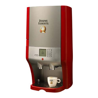
INTRODUCTION AND SAFETY Introducing The Cafitesse 60 is a liquid coffee dispenser for small outlets in the out−of−home market with an average consumption of 30 cups per day. The dispenser can deliver a variety of drinks subject to the choice of the customer for the following combination of ingredient packs: D coffee &... -
Page 6: Safety Instructions
Back Office Manual Safety instructions 1.2.1 General remark concerning safety This subsection is intended as an overview of the warnings and instructions used in this manual that must always be observed. The following general safety precautions apply to the operation and maintenance of the dispenser and must always be observed. - Page 7 Back Office Manual OPERATION D Do not use the dispenser for other than the intended use. D The dispenser is intended for in−door operation only. D Do not place the dispenser too close to a sink (wet) or cooking device (hot). D The liquids delivered by the dispenser are hot.
- Page 8 Back Office Manual INGREDIENT HANDLING D Ensure that the cooling compartment is properly closed at all times (the ingredient quality may otherwise deteriorate). D Store ingredient packs only in a refrigerator at a temperature below 6°C/42.8°F. D Always check the expiration date on the package (‘best before date’) and use the ingredient pack that has been stored for the longest period (first−in, first−out principle).
-
Page 9: Unpacking And Installation
Back Office Manual UNPACKING AND INSTALLATION Installation requirements D Required tools − Torx T10 and T15 screwdriver. − Torque wrench (to assemble cold plate). − Crosshead screwdriver (ventilator). − Service device (to adjust set volumes, coffee − Socket head wrench (M4, coil) strength, etc.). -
Page 10: Installation Procedure
Back Office Manual Installation procedure (US) Fig. 2 Installation: Fixed water connection Fig. 3 Installation: Removable water tank * The numbers correspond with the steps of the procedure. 1. Unpack 2. Install drip tray 3. (Re−)place button name−plates 4. Attach product stickers 5. - Page 11 Back Office Manual 2.2.2 Install drip tray and drip grid Fig. 5 Drip tray 2.2.3 (Re−)place button name−plates 1. Open the door. 2. Remove the two caps (Fig.6 a. + b.). 3. Remove the front−cover (Fig.6 c.). 4. Remove the push buttons with the name−plates (Fig.7 ). 5.
-
Page 12: Water Supply
Back Office Manual 2.2.5 Water supply 2.2.5.1 Fixed water connection Important − Ensure that the installation conditions are met before you install the fixed water connection (see section 2.1). − Always observe local regulation regarding plumbing! 1. Connect the water stop. (Specifications see section 5.7.1.) 2. - Page 13 Back Office Manual 2.2.6 Connect the power cord The boiler fills with water and the dispenser will go in the ’off’ mode. Immediately hereafter the Peltier element will be activated. The temperature will appear in the display until it reaches 5°C. For NSF the temperature of the cooling system will always be displayed.
-
Page 14: Handing Over The Dispenser To The Customer
Back Office Manual 2.2.10 Program and calibrate Go to the ’Service Mode’ to calibrate the dispenser: 1. Run the Automatic Temperature Adaptation Program (ATAP, see section 4.2.7). Optional, see section 5.1.6.1 for details. 2. Calibrate the water dosing quantity (section 4.2.4) Go to the ’Operator Mode’... -
Page 15: Main Components
Back Office Manual Main components Fig. 14 Main components a. Water tank lid (removable water tank only) h. Cooling compartment door b. Water tank (removable water tank only) i. Operation panel c. Door lock j. Power on / stand−by button d. -
Page 16: Specifications
Back Office Manual Specifications System Pack size Height 230 mm / 9.0” Width 090 mm / 3.5” Depth 090 mm / 3.5” Dispenser size Height 675 mm / 26.6” Width 420 mm / 16.5” Depth 400 mm / 15.7” Weight 26.5 kg filled with water and 2 packs 31.5 kg... -
Page 17: Faults
Back Office Manual FAULTS Dispenser status/error indications 3.1.1 Dispenser status Display Meaning Cause Action message The symbol ”replace The right−hand ingredient Replace the empty ingredient pack. right−hand ingredient pack a d g ed e pack is empty The right−hand ingredient Check that the ingredient pack is (coffee)”... - Page 18 Back Office Manual Display Meaning Cause Action message The symbol ”water tank The water tank contains too Fill the water tank with fresh water. empty” shows in the display. little or no water. The water tank is incorrectly Check that the water tank is correctly (Water tank version) positioned or not present.
- Page 19 Back Office Manual Error indications 3.1.2 Error Complaint Possible cause Action code i 02 The boiler doesn’t heat−up High temperatue safety Reset the high temperatue safety (after 1800 sec.). (a e 800 sec ) switch is in effect. switch. Boiler−element defective. Replace boiler.
- Page 20 Back Office Manual Error Complaint Possible cause Action code i 35 An over current detected on Short circuit. Check/replace defective part. the Peltier. i 39 Cool box (longer than 12 Door was not closed. Replace ingredient packs and close hours over 7_C / 44,6_F). hours over 7 C / 44,6 F).
-
Page 21: Troubleshooting
Back Office Manual Troubleshooting Type Complaint Cause Action No water is dosed. Pump motor defective. Check voltage PCB − pump motor. Water Replace defective part. Check/replace pump motor Float sticks in high position. Check on roughness of float and float needle. Replace defective part. - Page 22 Back Office Manual H3 − 6 Version 1.00 March 2006 Faults...
-
Page 23: Operator Mode
Back Office Manual PROGRAMMING MODE (Software version 5.05) Operator mode Section 4.1.1 Section 4.1.2 Section 4.1.3 Optional This function shall be visible for the customer, when it is activated in the service menu in Section 4.2.8 Section 4.1.4 ’Other settings’ Section 4.1.5 Section 4.1.6 Section 4.1.7... - Page 24 Back Office Manual 4.1.1 Counters H4 − 2 Programming Version 1.00 March 2006...
- Page 25 Back Office Manual 4.1.2 Cleaning Version 1.00 March 2006 Programming H4 − 3...
- Page 26 Back Office Manual 4.1.3 Descaling 4.1.3.1 Fixed water connection 4.1.3.2 Water tank version Till this step an escape is possible by pressing the stop buttun for more the 10 seconds. Till this step an escape is possible by pressing the When renegite has stop buttun for more the entered the descale...
- Page 27 Back Office Manual 4.1.4 Clock settings 4.1.5 Language settings Version 1.00 March 2006 Programming H4 − 5...
- Page 28 Back Office Manual 4.1.6 Text settings 4.1.7 Almost empty detection FUNCTIONALITY If pack is out of the dispenser for more then 10 seconds it will ask if it is a new or the existing pack > new pack, confirm by enter >...
-
Page 29: Service Mode
Back Office Manual Service Mode Section 4.1.10 Section 4.2.1 Section 4.2.2 Section 4.2.3 Section 4.2.4 Section 4.2.5 Section 4.2.5 Section 4.2.5 Section 4.2.5 Section 4.2.6 Section 4.2.7 Section 4.2.8 Section 4.2.9 Section 4.2.10 Version 1.00 March 2006 Programming H4 − 7... - Page 30 Back Office Manual 4.2.1 Error logs 25 Memory positions available If this is reached the 26 error log is placed on the 1 memory position. H4 − 8 Programming Version 1.00 March 2006...
- Page 31 Back Office Manual 4.2.2 Counters Version 1.00 March 2006 Programming H4 − 9...
- Page 32 Back Office Manual 4.2.3 Machine setting When this setting is chosen the automatic switch over is automatically activated. 4.2.4 Calibration H4 − 10 Programming Version 1.00 March 2006...
-
Page 33: Button Settings
Back Office Manual 4.2.5 Button settings Volume: recipe dependent Only possible with: D Coffee D Coffee creme Ratio: recipe dependent Only possible with: D Cappuccino D Café au lait Version 1.00 March 2006 Programming H4 − 11... - Page 34 Back Office Manual 4.2.6 Hot water settings H4 − 12 Programming Version 1.00 March 2006...
- Page 35 Back Office Manual 4.2.7 Boiler settings Ca. 15 min. Empty the drip−tray, after running the ATAP! Version 1.00 March 2006 Programming H4 − 13...
-
Page 36: Other Settings
Back Office Manual 4.2.8 Other settings When switched ON in the service menu, the customer can change themselves the coffee volume and coffee strengths in the operator menu. When you don’t want this option available it shall be switched to OFF. Position Signal after Total water hardness... -
Page 37: Clock Settings
Back Office Manual 4.2.9 Clock settings Next page Version 1.00 March 2006 Programming H4 − 15... - Page 38 Back Office Manual Previous Page Machine Coffee / Coffee Milk / Coffee settings Coffee / Decaf (Decaf) Cleaning Never − settings Every day Every day Twice a week Twice a week Every week − Twice a week means: B B B B B B B Sunday Monday Tuesday...
- Page 39 Back Office Manual 4.2.10 I/O tests Version 1.00 March 2006 Programming H4 − 17...
-
Page 40: Service Device
Back Office Manual Service device 4.3.1 General The service device is equipped with a 9V alkaline block battery. There is a danger of an explosion due to mishandling. The battery may not be recharged, disassembled, short−circuited, burnt or exposed to temperatures above 100 5 C or water. - Page 41 Back Office Manual 4.3.2 Programming 1. Switch the dispenser to stand−by. 2. Plug the service device into the 9 pins D−connector (standard service device connector). 3. Switch the service device on. 4. Switch the dispenser on. The programming mode is now enabled. Scroll through the main programming menu with the up/down keys (see the service mode flow charts, section 4.2) and press [input] to enter a sub−menu to change any settings.
-
Page 42: Summary Of Standard Machine And Receipe Settings
Back Office Manual Summary of standard machine and receipe settings 4.4.1 Standard version Machine settings Descale Temperature Eco time Unit fahrenheit Language Nederlands Show temperature Text in user mode Show ’Caution hot liquid’ Date format MM−DD−YY" Cleaning settings: Almoste empty detection Maandag Ratio adjust allowed Time... -
Page 43: Machine Settings
Back Office Manual 4.4.2 USA/CND version Machine settings Descale Temperature Eco time Unit fahrenheit Language English Show temperature Text in user mode Show ’Caution hot liquid’ Date format MM−DD−YY" Cleaning settings: Almoste empty detection Monday Ratio adjust allowed Time 12:00:00 Watertank version Eeprom name 002.066.205... - Page 44 Back Office Manual H4 − 22 Programming Version 1.00 March 2006...
-
Page 45: Functions
Back Office Manual FUNCTIONS Water system (A) 5.1.1 Functional description The water system of the Cafitesse 60 dispenser consist of the following components: 1. Water supply 2. Inlet valve 3. Float tank 4. Pump and rotor 5. Boiler 6. Water selector The water system is based on displacement technology, minimizing the need for pumps for water circulation. -
Page 46: Inlet Valve
Back Office Manual 5.1.2 Water Supply The Cafitesse 60 dispenser exists in two versions: D Dispenser with water tank D Dispenser with fixed water supply 5.1.2.1 Dispenser with water tank The dispenser with a cold water tank is equipped with: D a removable 2.9 liters / 98.1 fl oz. -
Page 47: Water Pump
Back Office Manual 5.1.4 Float tank All dispensers have a small float tank (Fig.20 a.) that forms a communicating vessel with the boiler. The purpose of the float tank is: D prevent the pump (Fig.20 b.) from running dry as result of low water pressure or an empty water tank, D prevent water running back from the boiler after the pump has stopped. - Page 48 Back Office Manual 5.1.6 Boiler Each time an user presses one of the selection keys the water pump (Fig.17 g.) will drive a fixed volume of water into the boiler (Fig.17 i.). The boiler (Fig.17 i.) has a capacity of 2.25 liters of water. Because the specific weight of hot water is less than the specific weight of cold water, the hot water inside the boiler will always float upwards and be driven through the boiler outlet into the water selector.
- Page 49 Back Office Manual 5.1.6.1 The Automatic Temperature Adjustment Program (ATAP) To calibrate the boiling point of the dispenser to extraordinary conditions, the service mode of the dispenser supports the special Automatic Temperature Adjustment Program (see section 4.2.7). You may need this option in situations where the local atmospheric pressure is significantly less than at sea level.
- Page 50 Back Office Manual 5.1.7 Water selector Each time an user presses one of the selection keys, the water pump (Fig.17 g.) will drive a fixed volume of cold water into the boiler that will displace the hot water into the water selector. The water selector routes the hot water to the mixer through (see section 5.3 Product delivery) to allows mixing the water with the required ingredients to prepare the drink that was selected by the user.
-
Page 51: Replacing Components
Back Office Manual 5.1.8 Replacing components 5.1.8.1 Pump 1. Unplug the power cord! 2. Close the water supply or remove the water tank. 3. Open the door of the dispenser. 4. Remove the left cover (Fig.26 ). 5. Disconnect two tubes (Fig.28 a.+b.). 6. - Page 52 Back Office Manual 5.1.8.3 Float tank 1. Unplug the power cord! 2. Close the water supply or remove the water tank. 3. Remove the drip tray. 4. Empty the boiler: D Place a suitable container (ca. 3.0 liters / 96.2 fl oz) in front of the dispenser.
- Page 53 Back Office Manual 5.1.8.6 Boiler 1. Unplug the power cord! 2. Close the water supply or remove the water tank. 3. Remove the drip tray. 4. Empty the boiler: D Place a suitable container (ca. 3.0 liters / 96,2 fl oz) in front of the dispenser.
- Page 54 Back Office Manual 5.1.8.8 Water selector motor 1. Unplug the power cord! 2. Close the water supply or remove the water tank. 3. Open the door of the dispenser. 4. Remove the left cover (Fig.26 ). 5. Disconnect the two tubes (Fig.34 a+ b) from the water selector cap. 6.
-
Page 55: Dosing System (C)
5.2.1 Ingredient packs The Cafitesse 60 dispenser is based on the patented liquid ingredient packs as designed by Sara Lee. Different sizes of ingredient packs exist. The dispenser can only accept ingredient packs with a volume of the 1.25 liters or a volume of 0,75 liters. The ingredient packs are non−returnable Bag−in Box (BIB) packages with a dedicated dosing tube. - Page 56 Back Office Manual 5.2.2 Replacing components 5.2.2.1 Mixer motor unit 1. Unplug the power cord! 2. Open the door of the dispenser. 3. Remove the trough. 4. Unscrew the mixer motor unit (Fig.39 a). 4. Unscrew the mixer motor unit (Fig.39 a). 5.
- Page 57 Back Office Manual 5.2.2.4 Light sensor ’trough detection’ 1. Unplug the power cord! 2. Remove the trough. 3. Unscrew the mixer motor unit (Fig.39 a). 4. Unscrew (4 screws) the service panel (Fig.40 ). 5. Disconnect the flat cable (Fig.45 a.) from the light sensor. 6.
-
Page 58: Product Delivery (D)
Back Office Manual Product Delivery (D) 5.3.1 Functional description Fig. 46 Product delivery a. Coffee pack or other ingredient g. Mixing chamber b. Coffee pack h. Beverage outlet Water inlet from the waterselector Hot water outlet d. Dosing position by other ingredient pack Chute (typically Coffee) e. -
Page 59: Cooling System (F)
Back Office Manual Cooling System (F) The cooling system consists of the following components: D Cooling compartment D Peltier elements D Airflow system 5.4.1 Cooling Compartment a. Cooling compartment b. Temperature sensor Cold plate d. Peltier e. Foam seal, cold plate Foam seal, Peltier g. - Page 60 Back Office Manual 5.4.2 Peltier elements Two Peltier elements (Fig.47 d.) at the back of the cooling compartment preserve the temperature inside the cooling compartment between 2 5 °C (35.6 41 °F) provided that the ambient temperature of the dispenser does not exceed the specifications listed in section 2.1 Installation requirements. Where on one side the Peltier element can generate cold to cool the cooling compartment, the opposite end of the Peltier element will heat up to remove its energy.
- Page 61 Back Office Manual 5.4.4 Replacing components 5.4.4.1 1. Unplug the power cord! 2. Remove the back cover. 3. Remove the funnel. Mark the position of the fan (Fig.48 ). 4. Disconnect the connector. 5. Remove the fan (Fig.49 ). Fig. 48 Mark fan position 6.
- Page 62 Back Office Manual 5.4.4.4 Peltier elements Handle the Peltier elements with care they are very sensitive to breakage. 1. Unplug the power cord! 2. Remove the back cover. 3. Remove the funnel. 4. Remove the two socket−head screws (M5) (Fig.50 ). 5.
-
Page 63: Housing (G)
Back Office Manual Housing (G) The dispenser is based on a U−shaped metal frame. All side panels and the door can be removed using a standard posidrive screwdriver (or TorqueR T15) 5.5.1 Dispenser with Fixed Water Supply To access the Water System, only remove left−side cover using: D 3 screws on the outside of the dispenser D 3 screws on the inside of the dispenser To access the electrical System, only remove right−side cover using:... - Page 64 Back Office Manual 5.5.2 Dispenser with Water Tank To access the Water System 1. remove the water tank 2. remove left−side cover using: D 4 screws on the outside of the dispenser D 2 screws on the inside of the dispenser To access the Electrical System, only remove right−side cover using: D 3 screws on the outside of the dispenser D 3 screws on the inside of the dispenser...
- Page 65 Back Office Manual 5.5.3 Replacing components 5.5.3.1 Door of the dispenser 1. Unplug the power cord! 2. Open the door of the dispenser. 3. Disconnect the ground wire. 4. Disconnect the flat cable 4.1 from the control board: 4 1 1 R 4.1.1 Remove the right cover (Fig.61 ).
-
Page 66: Machine Control (K)
Back Office Manual Machine Control (K) 5.6.1 Functional description The complete control system of the dispenser is be divided in to 3 items. D Power Supply D Keyboard D Control board 5.6.1.1 Power supply Trafo The power supply transforms the AC voltage connected to the main power inlet to an (un)regulated 24V DC voltage for the control board. - Page 67 Back Office Manual 5.6.1.4 Control board components a. B2 left b. B2 right Peltier / Fan d. Service device e. Display Temperature sensor (NTC) cooling g. Temperature sensor (NTC) boiler (top) h. Water selector Cold water unit connection Level water tank On / Off switch Float m.
- Page 68 Back Office Manual 5.6.1.5 Electrical diagram Standard version (700.406.686C) brown blue orange grey brown black brown blue orange grey brown black black black blue − 20V2 black − 1.6 At brown yellow white − blue black grey pink secondary 22V primary 230V a.
- Page 69 Back Office Manual 5.6.1.6 Electrical diagram USA/CND version (700.406.695E) brown blue orange grey brown black brown blue orange grey brown black black black blue − 20V2 black − 24 Volt 120 Volt a. Empty detection (left) Temperature sensor (NTC) u. Trough detection b.
- Page 70 Back Office Manual 5.6.1.7 Electrical diagram GB version (700.406.696B) brown blue orange grey brown black brown blue orange grey brown black black black blue − 20V2 black − 1.6 At brown yellow white − blue black grey pink secondary 22V primary 230V a.
- Page 71 Back Office Manual 5.6.2 Replacing components 5.6.2.1 Fuse (controle board) 1. Unplug the power cord! 2. Open the door of the dispenser. 3. Remove the right−cover (Fig.65 ). 4. Replace the the fuse (Fig.66 a.) and assemble in reverse order. Fig.
- Page 72 Back Office Manual 5.6.2.3 Control board The spare part (control board) will be delivered without EEPROM (containing the receipt software). 1. Unplug the power cord! 2. Open the door of the dispenser. 3. Remove the right−cover (Fig.65 ). 4. Disconnect all wiring. 5.
- Page 73 Back Office Manual 5.6.2.5 Power pack (USA/CND version) To replace the switch mode powerpack (Fig.69 a.) and relay (Fig.69 b.): 1. Unplug the power cord! 2. Open the door of the dispenser. 3. Remove the right cover (Fig.65 ). 4. Remove the protection plate (Fig.69 c.). 5.
- Page 74 Back Office Manual 5.6.2.6 Keyboard 1. Unplug the power cord! 2. Open the door of the dispenser. 3. Remove the two caps (Fig.70 a. + b.). 4. Remove the front−cover (Fig.70 c.). 5. Remove the two screws that hold the keyboard (Fig. 71 a.+ b.) 6.
-
Page 75: External Options (L)
Back Office Manual External options (L) WHAT REQUIRED Water stop valve For protection of the water supply system. Blocks the supply line when more than a specific quantity of water (adjustable from 5 to 30 liters (1.3 to 7.9 gal) flows at once. This valve, however, only protects against relatively big leaks. -
Page 76: Setting The Water Quantity
Back Office Manual Setting the water quantity D In the bottom part of the water stop valve (inside the connection for the supply hose), there is a scale with an adjustable indicator (B) (Fig. 73 ). D Each digit corresponds to a water flow quantity of approx. 5 liters (1.3 gal). (example: 3 = approx. -
Page 77: Payment System (P)
Back Office Manual Payment system (P) 5.8.1 Functional description See also Addendum: D The Cashflow 350 A PPLICATIONS ESIGN UIDE D The Cashflow 350 P RODUCT AINTENANCE ANDBOOK 5.8.2 Installing the payment system 1. Unplug the power cord! 2. Remove the back and right cover. 3. - Page 78 Back Office Manual H5 − 34 Function (Pay System) Version 1.00 March 2006...
-
Page 79: Preventive Maintenance (Reserved)
Back Office Manual PREVENTIVE MAINTENANCE (RESERVED) Version 1.00 March 2006 Preventive Maintenance H6 − 1... - Page 80 Back Office Manual H6 − 2 Preventive Maintenance Version 1.00 March 2006...
-
Page 81: Service Code Numbers
Back Office Manual SERVICE CODE NUMBERS Water system (A) 7.1.1 Water system (1#2) A11. A18. A12. A13. A33. A14. A32. A15. A34. A19. A35. A46. A16. A20. A36. A39. A21. A40. A22. A37. A17. A41. A23. A42. A24. A38. A43. A44. - Page 82 Back Office Manual 7.1.2 Water system (2#2) A61. A59. A53. A61. A59. A57. A56. A54. A55. A58. A53. A60. A50. A51. A49. A54. A60. A49. A48. A64. A52. A47. A63. A51. A62. A63. A 10. Other fault in product delivery A 52.
-
Page 83: Dosing System (C)
Back Office Manual Dosing system (C) C11. C12. C13. C14. C15. C16. C17. C 10. Other fault in product delivery C 14. Empty C 19. Ingredient, milk (general) C 15. Coil C 20. Ingredient, cacao C 11. Coil assy, left C 16. -
Page 84: Product Delivery (D)
Back Office Manual Product delivery (D) D19. D18. D20. D17. D21. D16. D22. D15. D23. D24. D25. D14. D26. D13. D27. D28. D11. D12. D 10. Other fault in product delivery D 16. Trough release D 23. Mixer motor (general) D 17. -
Page 85: Cooling System (F)
Back Office Manual Cooling system (F) F12. F11. F20. F19. F14. F18. F17. F13. F16. F15. Other fault in product delivery Thermo protection Cold plate (general) Heat sink Temperature sensor Funnel Peltier Foam seal, Peltier Foam seal, cold plate Cover plate, thermo protection Version 1.00 March... -
Page 86: Housing (G)
Back Office Manual Housing (G) 7.5.1 Housing (1#2) G12. G11. G21. G32. G18. G17. G15. G16. G20. G25. G30. G27. G29. G31. G28. G26. G22. G24. G14. G19. G13. G23. G 10. Other fault in product delivery G 17. Screws, left cover outside G 24. - Page 87 Back Office Manual 7.5.2 Housing (2#2) G33. G39. G34. G27. G35. G36. G38. G37. G 10. Other fault in product delivery G 35. Grid, filter cooling fan G 39. Branding plate (RVS) (general) G 36. Sealing, door G 37. Lock handle, door G 33.
-
Page 88: Machine Control (K)
Back Office Manual Machine control (K) 7.6.1 Control and power board (Standard version) K11. K12. K13. K14. K17. K15. K16. K18. K19. K20. K22. K23. K21. K24. K25. K26. K28. K27. Other fault in product delivery Wiring and connector On/off switch (general) [Details, see section 5.6.1] Fixation hook, on/off switch... - Page 89 Back Office Manual 7.6.2 Control and power board (USA/CND version) K11. K12. K13. K14. K17. K15. K16. K31. K32. K20. K23. K24. K18. K33. K25. K29. K26. K30. Other fault in product delivery Wiring and connector Power pack (general) [Details, see section 5.6.1] Protection cover Main fuse Connector, service device...
- Page 90 Back Office Manual 7.6.3 Operation panel K34. K35. K36. K37. K42. K41. K40. K38. K39. Other fault in product delivery Selection button(s), keyboard Selection button(s) (general) Connector, flat cable Product label(s) Keyboard Foil, product buttons Foil, hot water button Stop button Display H7 −...
-
Page 91: Service Information Bulletins
Back Office Manual SERVICE INFORMATION BULLETINS Version 1.00 March 2006 Service Information H8 − 1... - Page 92 Back Office Manual H8 − 2 Service Information Version 1.00 March 2006...
-
Page 93: Modification Instructions
Back Office Manual MODIFICATION INSTRUCTIONS Upgrading the C60 software The C60 Cafitesse dispenser uses FLASH technology to save its software (referred to as firmware) into memory. Upgrading the firmware is easy and simple and requires a programming device and appropriate software running on a PC or notebook under Windows 95, Windows 98, Windows 98SE, Windows XP, Windows 2000 or Windows NT. - Page 94 Back Office Manual 9.1.3 Creating a C60 workspace After installing the “Hitachi Flash Development Toolkit” a workspace must be defined in order to be able to connect to the C60 dispenser and be able to upgrade its firmware. Create a workspace by selecting the “Create a new Workspace” button and then click “OK”. Now the name of the new workspace must be entered in the “Workspace Name”...
- Page 95 Back Office Manual A valid project name would be “C60”. Enter this name in the “Project Name” field and click “Next” to proceed. A new window appears asking to select the used microcontroller. Select the name of the used micro controller from the list: “H8S/2138AF”...
- Page 96 Back Office Manual A new window appears to setup the used crystal frequency. The crystal frequency must be 20.00 MHz. Enter this value and click “Next” to continue. The next window shows default values which should not be changed. Click “Next” to continue. The next window shows default values which should not be changed.
- Page 97 Back Office Manual The setup of a workspace is done only once. The second time the software will be started an existing workspace can be selected from the window as shown below: Select the created workspace “C60 Dispenser” and then click “OK”. 9.1.4 Adding C60 dispenser firmware files to the workspace Before new software (referred to as Firmware) can be loaded into the dispenser this software must be...
- Page 98 Back Office Manual The next window shows the file “C60_V4.0.4.mot” added to the “Target Files” folder. Please note: − The name of the MOT file may differ depending on the software version. Now save the workspace by selecting the “File” menu “Save Workspace”. 9.1.5 Upgrading the C60 dispenser The “Target Files”...
- Page 99 Back Office Manual Delete a MOT file from the “Target Files” folder by right clicking on the MOT file. The window will show like this: After removing the file from the “Target File” folder a new file can be added to this folder as described in the paragraph “Adding C60 dispenser firmware files to the workspace”.
- Page 100 Back Office Manual 9.1.6 Establishing a connection the PC/notebook and the C60 The following steps must be taken in order to put the dispenser in the upgrade mode: 1. Disconnect the mains power from the C60 and wait 10 seconds. 2.
- Page 101 Back Office Manual Now the following steps must be taken in order to load the new software into the C60 dispenser: 1. Connect to the C60: − Select the main menu item “Device” − Select “Connect to Device” in order to establish a connection between de PC/notebook and the C60 In the bottom window field text will appear showing that a connection is being established.
- Page 102 Back Office Manual If a connection failed to establish the text as shown below will appear in the bottom field: If an error occurred check the power, the cables and the connections. 2. Erase all blocks in the micro controller. −...
- Page 103 Back Office Manual After all blocks have been erased the bottom field shows the text as shown in the next window Now the micro controller is completely empty and ready for receiving new firmware. 3. Download the new firmware to the C60 −...
- Page 104 Back Office Manual After the transfer has been completed the window shows the following text: The C60 dispenser now holds an updated version of the firmware. Select “Disconnect from Device” from the “Device” menu to close down the connection. After the connection has been closed the window shows the following text: 4.
Need help?
Do you have a question about the Cafitesse 60 and is the answer not in the manual?
Questions and answers