
Related Manuals for GRASS VALLEY PERFORMER


Summary of Contents for GRASS VALLEY PERFORMER
-
Page 1: Instruction Manual
Instruction Manual T P 3 4 6 1 - 0 1 F I R S T P R I N T IN G : S E P T E M B E R 1 9 9 4 P ER FO RM E R D I G I T A L 1 0 X 1 R O U T I N G S W I T C H E R... - Page 2 Grass Valley Group. Grass Valley Group assumes no re- sponsibility or liability for any errors or inaccuracies that may appear in this publication.
-
Page 3: Table Of Contents
Preface About the Performer™ Manual......xiiv Glossary of Terms ........xviii Section 1 —... - Page 4 Model 100/110 to Performer (Conditional mode) ..2-26 Model 200 to Performer ......2-27 Model 300 to Performer .
- Page 5 20-TEN Protocol ....... 2-50 Performer S1 Switch Settings ....2-50 Remote Panel Switch Settings .
- Page 6 Contents Audio Follow Video ....... . 3-3 Breakaway ......... 3-4 Video Only .
- Page 7 Contents Performer ASCII Protocol ......3-32 Command Line ....... . 3-32 Command Strings .
- Page 8 Contents viii...
-
Page 9: Important Safeguards And Regulatory Notices
Important Safeguards and Regulatory Notices Information on the following pages provides important safety guidelines for both Operator and Service Personnel. Specific warnings and cautions will be found throughout the manual where they apply, but may not appear here. Please read and follow the important safety information, noting especially those instructions related to risk of fire, electric shock, or injury to persons. -
Page 10: Symbols And Their Meaning
Safeguards and Notices Symbols and Their Meaning The lightning flash with arrowhead symbol, within an equilateral triangle, alerts the user to the presence of “dangerous voltage” within the product’s enclosure that may be of sufficient magnitude to constitute a risk of electric shock to persons. The exclamation point within an equilateral triangle alerts the user to the presence of important operating and maintenance (servicing) instructions in the literature accompanying the... -
Page 11: Warnings
Safeguards and Notices Warnings Heed all warnings on the unit and in the operating instructions. Do not use this product in or near water. Disconnect ac power before installing any options. This product is grounded through the grounding conductor of the power cord. To avoid electrical shock, plug the power cord into a properly wired receptacle before connecting the product inputs or outputs. -
Page 12: Cautions
Safeguards and Notices Cautions To prevent damage to equipment when replacing fuses, locate and correct the trouble that caused the fuse to blow before applying power. Verify that all power supply lights are off before removing power supply or servicing equipment. Use only specified replacement parts. -
Page 13: North American Power Supply Cords
Safeguards and Notices North American Power Supply Cords This cord is supplied with a molded grounding plug (NEMA 5- 15P) at one end and a molded grounding connector (IEC 320-C13) at the other. Conductors are CEE color coded, light blue (neutral), brown (line), and green/yellow (ground). -
Page 14: Emc Regulatory Notices
Safeguards and Notices EMC Regulatory Notices Federal Communications Commission (FCC) Part 15 Information This equipment has been tested and found to comply with the limits for a Class A digital device pursuant to Part 15 of FCC Rules. These limits are designed to provide reasonable protection against harmful interference in a commercial environment. -
Page 15: Germany - Ftz
Vfg. 243/46 (1992). The German postal service was notified that the equipment is being marketed. The German Postal Service has the right to re-test the equipment and verify compliance. Grass Valley Group, Inc. P.O. Box 1114 Grass Valley, CA 95945 U.S.A. - Page 16 Safeguards and Notices...
-
Page 17: Preface
About the Performer Manual ™ The manual contains installation, operation, and service instructions for Performer and its optional accessories and control panels. The manual contains the following sections. Product Description—An overview of Performer, including a functional description and a table of specifications. -
Page 18: Glossary Of Terms
Preface Glossary of Terms The terms defined below are used in this manual. We have listed them here for your convenience. AC coupled A method of connecting one circuit to another so as to trans- mit the varying AC characteristics of the signal while blocking the static (DC) characteristics. - Page 19 Glossary of Terms level offset The addresses of a level controlled by a control panel which have been incremented to a higher set of numbers. An independently controllable stratum of signals within a level(s) routing switcher. Typically, a routing switcher will have a lev- el of video and one or more audio levels.
- Page 20 Preface vertical interval strobe (VI) In relation to video switching applications, a signal sent to indicate the beginning of the vertical interval. Re-establishment of a fixed DC reference level for the video video clamped signal. X-Y mode A switching matrix which places inputs (sources) on an X axis and outputs (destinations) on a Y axis.
-
Page 21: Section 1 - Product Description
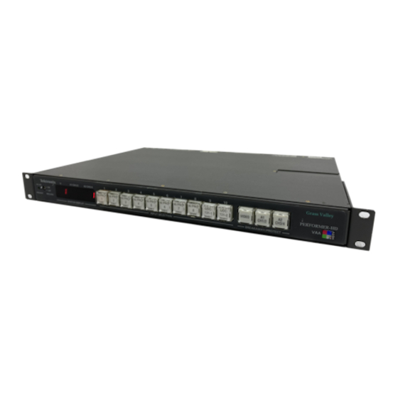
Product Description Introduction This section provides a general description of the serial digital version of the Performer™ 10 x 1 Routing Switcher. Included are Product features Functional description Specifications Product Features Performer is a serial digital, 10-input by 1-output, video with dual (AES/EBU) audio routing system from Grass Valley Group. - Page 22 Performer options include: Tally relays for 10 inputs & Joystick Override control Remote control panel Performer circuitry resides in a sealed, 1 rack unit frame. The standard unit contains just four printed circuit boards. These are: Rear Motherboard (two versions available)
-
Page 23: Functional Description
Functional Description See descriptions and the block diagram on the following pages. System The PERFORMER Serial Digital Video and AES/EBU Digital Audio10X1 routing switcher. It is available in four (4) basic models (configured with either BNC or D type audio connectors and supplied with either local or remote control panel) as described below. - Page 24 • AUTO mode: provides automatic bit rate selection when input rates are different. The PERFORMER automatically detects the input bit rate and switches to the correct rate, i.e. with D1 at Input 1 and D2 at Input 2 user switches from Input 1 to Input 2. The switcher will automatically switch to the new rate.
-
Page 25: Rear Motherboard
Functional Description Rear Motherboard All inputs and outputs are through connectors on the Rear Motherboard. This board has only mechanical functions and mounts no active circuitry. There are two different types of rear connector panels available (unbalanced BNC type audio connectors and balanced D type audio connctors). -
Page 26: Vaa Board
Control circuitry Parameter-determining switches Vertical Interval Strobe generating circuitry Performer video processing circuitry consists of: ASIC cable equalizers, an ASIC serial crosspoint, and an ECL line driver. Serial bit stream at inputs is converted to parallel, and processed in parallel digital domain, to extract line ID information and to generate the vertical interval switching strobe. -
Page 27: Power Supply Board
Functional Description the state of the three “breakaway” buttons (V, AES1, and AES2). The Performer is capable of full breakaway operation, meaning that video may be separately switched from audio and even the two audio channels may be separately switched one from the other. - Page 28 Product Description Section 1 — VIDEO/MICROPROCESSOR CONTROLLER FUNCTIONAL BLOCK DIAGRAM 16X8 VIDEO AUTOMATIC CROSSPOINT EQUALIZERS SERIAL Direct Mode VIDEO LINE OUTPUTS DRIVER VIDEO INPUTS Indirect Mode DESERIALIZER (1 - 10) COPROCESSOR Bit Rate Switch (front panel) Direct Auto 11th input 143Mb/s 177Mb/s FIELD PROGRAMMABLE...
-
Page 29: Functional Block Diagram
Functional Description AUDIO FUNCTIONAL BLOCK DIAGRAM Channel 1 RS485 AES/EBU CH 1 AUDIO 10 X 1 LINE OUTPUTS INPUTS AUDIO DRIVER (Ch 1) MULTIPLEXER LINE RECEIVERS AES/EBU Channel 2 RS485 AUDIO CH 2 10 X 1 LINE INPUTS OUTPUTS AUDIO DRIVER (Ch 2) MULTIPLEXER... - Page 30 Product Description Section 1 — Performer Specifications Table 1-1. Performer Specifications Parameter Performanace Serial Digital Video Inputs Video Data Type Serial Digital conforms to SMPTE 259M (D1, D2N, D2P) Number of inputs Ten (10) Data Format Selection Internal Selector Switch Input Impedance 75Ω...
- Page 31 Functional Description Table 1-1. Performer Specifications (continued) Parameter Performanace AES/EBU Digital Audio Outputs Audio Data Type Serial Digital conforms to AES3-1991 (ANSI S4.40-1985) Number of Outputs Two per audio matrix (4 ea. total) Output Connector Balanced female “D” or unbalanced 75Ω BNC Output Level 1.0Vp-p, ±10%, into 75Ω...
- Page 32 Product Description Section 1 — 1-12...
-
Page 33: Section 2 - Installation
Installation Introduction This section provides installation information for Performer 10 x 1 Routing Switcher. Included here are: Installation Overview Common Configurations Installation Reference Installation Overview This section provides step-by-step installation instructions for the Performer™ in the following order: Uncrating Unpacking and inspecting the equipment. -
Page 34: Uncrating
Section 2 — Uncrating When you opened the box in which your Performer arrived, you found this guide. If there was more than one box, they were each assigned a number. In the box labeled number 1, there was a System Packing List. -
Page 35: Button Labeling
NOTE: Tally Board and Looping Cable Option .If you order the Performer and the Tally Board or Looping Cable Option at the same time, the board is installed at the factory. If you order the Tally Board or Looping Cable Option later, see the Installation Reference section and install it as described. - Page 36 Installation Section 2 — Rack-Mounting the Performer Performer is designed to mount in a 19-inch equipment rack. The frame occupies 1 RU (Rack Unit, 1.75 inches/4.45 cm) of vertical space. The illustration below shows you how to mount the frame in the rack.
- Page 37 • AUTO mode: provides automatic bit rate selection when input rates are different. The PERFORMER automatically detects the input bit rate and switches to the correct rate (i.e. with D1 at Input 1 and D2 at Input 2 user switches from Input 1 to Input 2. The switcher will automatically switch to the new rate.) NOTE: The...
-
Page 38: Cabling
Installation Section 2 — Cabling Performer cabling is straightforward. Refer to the illustration. Input 1, Input 3, Input 5, Input 7, Input 9, Output (+) (–) (s) (+) (–) (s) (+) (–) (s) (+) (–) (s) (+) (–) (s) (+) (–) (s) - Page 39 Installation Overview utput (–) (s) OPTION AUDIO 1 IN V OUT VIDEO IN REMOTE Video Out (V OUT 1 and 2) Video IN (1-10) Single video output has two 1. Using 75-ohm coaxial cable, points of connection. connect your number 1 video source to Video IN 1 BNC.
-
Page 40: Switcher Power-Up
At this point, Performer does a self-test. NOTE: Displays may be accelerated by pressing any of buttons 1 through 8 on the Performer front panel or skipped entirely by pressing any other button. Status information is displayed in the following order:... -
Page 41: Common Configurations
Performer Remote to Performer PC (Performer ASCII) to Performer PC (TEN-XL ASCII) to Performer PC (Performer ASCII) to Modem to Performer PC (TEN-XL ASCII) to Modem to Performer TEN-XL SCP (XY-mode) to Performer TEN-XL SCP (XY-mode) to Modem to Performer... - Page 42 Section 2 — Performer Setup Switch Location While setting up your Performer, you may need to change the settings of switches S1, S2, and S3 located within the frame. You won’t have to remove the top cover to access these switches because a small “slide”...
- Page 43 Common Configurations Performer Remote to Performer Performer Remote Control Panel Performer Grass Valley Group Grass Valley Group A1 CH1/2 A2 CH3/4 360Mb 270Mb AUTO 177Mb DIRECT PERFORMER–SD PERFORMER–SD VIDEO VIDEO AUDIO AUDIO CH1/2 CH3/4 143Mb REMOTE Dot indicates switch down...
- Page 44 Installation Section 2 — PC (Performer ASCII) to Performer Performer PC (Performer ASCII) Grass Valley Group A1 CH1/2 A2 CH3/4 360Mb 270Mb AUTO 177Mb DIRECT VIDEO PERFORMER–SD CH1/2 CH3/4 143Mb Baud 9600 Data Bit 7 Dot indicates Parity switch down...
-
Page 45: Pc (Performer Ascii) To Performer (Cont.)
Common Configurations PC (Performer ASCII) to Performer (cont.) The following is an example of a Performer ASCII string used to control a Performer via a PC. The command string will switch video input number 5 on all levels of the Performer (video, audio 1, and audio 2). -
Page 46: Pc (Performer Ascii) To Modem To Performer
Installation Section 2 — PC (Performer ASCII) to Modem to Performer Performer PC (Performer ASCII) Modem* Grass Valley Group A1 CH1/2 A2 CH3/4 360Mb 270Mb AUTO PERFORMER–SD 177Mb DIRECT VIDEO CH1/2 CH3/4 143Mb Baud 1200 Data Bit 7 Dot indicates... -
Page 47: Pc (Performer Ascii) To Modem To Performer (Cont.)
Common Configurations PC (Performer ASCII) to Modem to Performer (cont.) The following is an example of a Performer ASCII string used to control a Performer via a PC. The command string will switch video input number 5 on all levels of the Performer (video, audio 1, and audio 2). - Page 48 Installation Section 2 — PC (TEN-XL ASCII) to Performer PC (TEN-XL ASCII) Performer Grass Valley Group A1 CH1/2 A2 CH3/4 360Mb 270Mb AUTO 177Mb DIRECT VIDEO PERFORMER–SD CH1/2 CH3/4 143Mb Baud 9600 Data Bit 7 Dot indicates Parity switch down...
-
Page 49: Pc (Ten-Xl Ascii) To Performer (Cont.)
PC (TEN-XL ASCII) to Performer (cont.) The following is an example of a TEN-XL ASCII string used to control a Performer via a PC. The command string will switch video input number 4 and both audio channels to input number 6. -
Page 50: Pc (Ten-Xl Ascii) To Modem To Performer
Installation Section 2 — PC (TEN-XL ASCII) to Modem to Performer Performer PC (Performer ASCII) Modem* Grass Valley Group A1 CH1/2 A2 CH3/4 360Mb 270Mb AUTO 177Mb DIRECT VIDEO PERFORMER–SD CH1/2 CH3/4 143Mb Baud 1200 Data Bit 7 Dot indicates... -
Page 51: Pc (Ten-Xl Ascii) To Modem To Performer (Cont.)
PC (TEN-XL ASCII) to Modem to Performer (cont.) The following is an example of a TEN-XL ASCII string used to control a Performer via a PC. The command string will switch video input number 4 and both audio channels to input number 6. -
Page 52: Ten-Xl Scp (Xy-Mode) To Performer
REMOTE TEN-XL Performer 25 pin 25 pin Female Male TXD 2 16 RXD RXD 3 3 TXD GND 7 18 GND Cable (max 50'/15.25m) TNX-IRS (056857) To control more than one Performer, see additional information in Installation Reference section. 2-20... -
Page 53: Ten-Xl Scp (Xy-Mode) To Modem To Performer
TNX-CTM (056862) *Disable or turn off modem response codes to terminal, or select the mode which sends them as numbers; disable or turn off command character echo. To control more than one Performer, see additional information in Installation Reference section. 2-21... -
Page 54: Ten-Xl Remote Panels To Performer
A1 OUT AUDIO 1 IN V OUT VIDEO IN REMOTE Performer 25 pin 25 pin Male Male Cable (max 1000'/305m) TNX-RCC (056851) Pins are one to one To control more than one Performer, see additional information in Installation Reference section. 2-22... -
Page 55: Tnx-Afv19 To Performer
Common Configurations TNX-AFV19 to Performer TEN-AFV19 Performer (Primary and Secondary) Note: Switch settings for S2 are different for primary and secondary, see below. TEN X Grass Valley Group Grass Valley Group A1 CH1/2 A2 CH3/4 360Mb 270Mb AUTO 177Mb DIRECT VIDEO PERFORMER–SD... -
Page 56: 20-Ten Xycp To Performer
25 pin Female Male RS485 (+) 1 RS485 (+) 150-ohm resistor RS485 (-) 2 RS485 (-) 18 GND Cable (max 2000'/610m) Three strand coax (Belden 8451) To control more than one Performer, see additional information in Installation Reference section. 2-24... -
Page 57: Model 100/110 To Performer (Always Follow Mode)
Common Configurations Model 100/110 to Performer (Always Follow mode) Performer (Always Follow mode) Model 100/110 Grass Valley Group A1 CH1/2 A2 CH3/4 360Mb 270Mb AUTO 177Mb DIRECT VIDEO PERFORMER–SD CH1/2 CH3/4 143Mb Baud 38400 Data bit 8 Dot indicates switch down... -
Page 58: Model 100/110 To Performer (Conditional Mode)
Installation Section 2 — Model 100/110 to Performer (Conditional mode) Model 100/110 Performer (Conditional mode) Grass Valley Group A1 CH1/2 A2 CH3/4 360Mb 270Mb AUTO PERFORMER–SD 177Mb DIRECT VIDEO CH1/2 CH3/4 143Mb Baud 38400 Data bit 8 Dot indicates switch down... -
Page 59: Model 200 To Performer
Common Configurations Model 200 to Performer Model 200 Performer Grass Valley Group Grass Valley Group A1 CH1/2 A2 CH3/4 360Mb 270Mb AUTO PERFORMER–SD 177Mb DIRECT VIDEO CH1/2 CH3/4 143Mb Baud 38400 Data bit 8 Parity Address 1 Dot indicates switch down... -
Page 60: Model 300 To Performer
Installation Section 2 — Model 300 to Performer Performer Model 300 Grass Valley Group Grass Valley Group A1 CH1/2 A2 CH3/4 360Mb 270Mb AUTO PERFORMER–SD 177Mb DIRECT VIDEO CH1/2 CH3/4 143Mb Baud 38400 Data bit 8 Parity Address 1 Dot indicates... -
Page 61: Installation Reference
Installation Reference Installation Reference The Installation Reference section may be viewed as two distinct installation sub-sections: Frame top cover removal/replacing Removing/replacing frame top cover Removing/replacing terminating resistors Remote connector cabling Option connector cabling Tally board option installation Looping cable option installation Access to internal switches via frame top “slide-cover”... -
Page 62: Frame Top Removal And Replacement
Installation Section 2 — Frame Top Removal and Replacement The Performer frame is EMI (electromagnetic interference) tight. To gain access to change factory settings and set operating voltage, it is necessary to remove the frame top cover. The illustration below shows you how. -
Page 63: Replacement
S T A T U S Replacement Wait until all configuration changes are complete. Then replace the top in reverse order from its removal. Performer setups are discussed on the following pages. When replacing the top, make sure you slide the lip into the front panel slot. -
Page 64: Removing/Replacing Terminating Resistors
Installation Section 2 — Removing/Replacing Terminating Resistors When using your unit with more than one other device, you must decide where your unit is to reside on the control bus. Depending on its location on the bus, you may need to remove resistor R400. If your unit will reside at the end of the bus, leave R400 in place If your unit will reside mid-bus, remove R400... -
Page 65: Remote Connector Cabling
Installation Reference Remote Connector Cabling The 25-pin, female D REMOTE connector provides a point of connection for: Optional remote control panel (RS485) RS232, RS422 interface External Vertical Interval Strobe Connector pin numbering is illustrated below. Table 2-4 lists the signal-to-pin number correlation. CAUTION If you are adding your own control device, using RS422 or RS485 control, you may need to construct a connecting cable. - Page 66 Installation Section 2 — Table 2-4. REMOTE Connector Pin Assignments - (continued) Signal VD (bit D of 4-bit binary video status) AA (bit A of 4-bit binary audio status) AB (bit B of 4-bit binary audio status) AC (bit C of 4-bit binary audio status) AD (bit D of 4-bit binary audio status) O (bit O of 5-bit binary source select) A (bit A of 5-bit binary source select)
-
Page 67: Option Connector Cabling
When used to connect Joystick Override or a custom control panel, an optional Tally Relay Board and cable/connector assembly must be installed in Performer. This installation is described next in this section. Once the Tally Relay Board and connector are installed, you can cable control and tally as Operation illustrated below and listed in Table 2-5. -
Page 68: Tally Board Option Installation
Section 2 — Tally Board Option Installation The Tally Board option allows you to use a custom control panel or Joystick Override to control the Performer, and provides tally relay closures which follow the video switching level. (See the Operation section for Tally Board function.) - Page 69 REMOTE Board When installing Tally Board, install blank header here to avoid chafing ribbon cables. 14, +5V OPTION CONNECTOR PIN NUMBERS SWA2 SWA1 SW10 SWITCHES, JOYSTICK OR CUSTOM CONTROL Switches are user-supplied. PERFORMER RELAYS COMMON OPTION CONNECTOR PIN NUMBERS 2-37...
- Page 70 Installation Section 2 — Table 2-5. OPTION Connector Pin Assignments, Tally Board Installed Signal Switch 1 Switch 2 Switch 3 Switch 4 Switch 5 Switch 6 Switch 7 Switch 8 Switch 9 Switch 10 Switch V (Video Only) Switch A1 (Audio 1 Only) Switch A2 (Audio 2 Only) GPI (Switch) Common, +5V Tally Relay 1...
-
Page 71: Looping Cable Option Installation
The OPTION slot is typically used to loop the REMOTE connector when more than one standard remote control panel is used or if the Performer is placed in Slave Mode and used with TEN-XLs or other Performers. Remove the blank cover from the OPTION cutouts. -
Page 72: Vertical Interval Strobe Selection
Section 2 — Vertical Interval Strobe Selection Performer generates its own Vertical Interval strobe, which times the switching of video so that switching occurs within a region of each video field when there is no active video. You may use either... -
Page 73: Switch Reference
C = a switch segment. For Switch 5, R = right direction; L = left direction. Table 2-6. Switch Reference, S1, 2, and 3 in Performer Switcher Segments Effect Switch 7 Data Bits Selectable for ASCII and Model 200 protocols only. - Page 74 Installation Section 2 — Table 2-6. Switch Reference, S1, 2, and 3 in Performer Switcher - (continued) Segments Effect Switch Address * 10XL ASCII SMPTE 3245-E Perf ASCII 10XL ASCII 10XL SMPTE 100/110, Always 100/110, Conditional Perf/20-TEN, Master 20-TEN, Slave...
-
Page 75: Switcher Polling Address
GVG Model 200 0-23 GVG Model 300 SMPTE 3245-E 40-255 (28H-FFH) NOTE: For addressing, refer to the instructions for the control panel you are using (page 2-54 f or Performer remote panel, or page 2-75 for TEN –20, 20–TEN remote panels) 2-43... -
Page 76: Polling Address, Non Gvg Ten-Xl Ascii Protocols
Installation Section 2 — Polling Address, Non GVG TEN-XL ASCII Protocols To determine a polling address, each segment of switch S1 is closed assigned a value from 1 through 128. When the segment is that value is added into the polling address. In the example below, the value of each segment is shown above the switch. -
Page 77: Serial Communications Protocol Selection
For ASCII and GVG Model 200 protocols, you will also set serial port data bits at 7 or 8. For other protocols, the data bits are automatically set at 8. Performer serial port stop bits are automatically set at 1. - Page 78 Use this protocol when you are controlling a TEN–XL switcher from a host computer using the TEN–XL’s modified SMPTE, and you wish to control the Performer as well. GVG Model 100 and 110 Use this protocol when you are controlling the Performer from the Grass Valley Model 100 or 110 Production Switcher.
-
Page 79: Control Panel Reference
Control Panel Reference Control Panel Reference This section contains reference information for the following control panels: Performer Serial Remote Control Panel TEN-XL Serial Control Panel TEN-20/20-TEN Panels and Serial Interface 2-47... -
Page 80: Performer Serial Remote Control Panel
Directions for doing this are described earlier in this section. When a 20-TEN protocol is selected, the Performer serial port is forced to 76.8K baud, 8 data bits, no parity regardless of Performer baud and parity-determining switches. In addition, the function of Performer‘s address selection switch (S1) changes to become a... - Page 81 Performers to be ganged on the same level and desti- nation number as the Master while avoiding bus conten- tion. Performer Remote/20–TEN Levels V, A1, and A2 within a Performer are treated as a Compatible, All Levels, single level; they switch simultaneously in response to Master Mode commands from control panel (breakaway still possible using Performer front-panel buttons).
-
Page 82: General Rules For Performer/Ten-20
Control Panel switch settings Performer S1 Switch Settings When the Performer is configured for one of the 20-TEN protocol variations, the function of S1 is to select source, destination, and level offset (in other protocols, it selects the address of the switcher). - Page 83 (1 most significant; 3 least) to select source offsets from 0 to 7. When a source offset of 0 is selected, Performer sources are numbered from 1 through 10. If a source offset of 1 is selected, Performer sources are numbered from 11 through 20.
- Page 84 (4 most significant; 6 least) to select destination offsets from 0 to 7. When a destination offset of 0 is selected, the Performer destination is 1. If a destination offset of 1 is selected, the Performer destination is 11. When a destination offset of 2 is selected, the Performer destination is 21.
- Page 85 (7 most significant; 8 least) to select level offsets from 0 to 3. When set to 0, the Performer level numbers (V, A1, and A2) are from 1 to 3. When set to 1, the Performer level numbers are from 2 to 4.
-
Page 86: Remote Panel Switch Settings
The source, destination, and level offset of the panel must match the switcher it controls. Diagnostic modes are Service Manual. described in the Performer Panel ID # As many as 32 communicating devices may be placed along a single RS485 bus. - Page 87 Control Panel Reference The switch is illustrated below and its possible segment position are listed in the following tables. SOURCE OFFSET 0 - 7 CONTROLLED DESTINATION 0 - 7 LEVEL OFFSET 0 - 3 The following table lists switch settings and the resulting source open closed offset.
- Page 88 Installation Section 2 — Controlled Destinations Offset Segments 4, 5, and 6 of switch S1 determine destination offset. The segments operate in binary fashion (4 most significant; 6 least) to select destination offsets from 0 to 7. When a destination offset of 0 is selected, the panel controls destination 1.
- Page 89 Control Panel Reference Level Offset Segments 7 and 8 of the switch determine level offset. The segments operate in binary fashion (7 most significant; 8 least) to select level offsets from 0 to 3. When set to 0, the remote panel controls levels from 1 to 3.
- Page 90 Installation Section 2 — Panel Protocol The final (four-position) switch, segments 2, 3, and 4, determines panel protocol. For normal operation, these segments should all be in the OFF position. If they are in any other position, the panel will not control switchers but will enter a diagnostic mode or an invalid condition.
-
Page 91: Ten-Xl Scp Switch Configuration
The TEN-XL Serial Control Panel may be set up in one of two modes, Dual and X-Y. In the Dual Mode, it can control up to two Performer switchers. In the X-Y mode, it can control up to ten Performer switchers. - Page 92 Performer when TEN-XL ASCII protocol is selected). Performer Address To set Performer address to be controlled by TEN-XL SCP in X-Y mode: Locate switch S1 on Performer (see Performer Setup Switch Location in Common Configurations section).
- Page 93 Baud Rate We recommend a baud rate of 9600 if you are cabling directly to the Performer(s) or a baud rate of which your modem is capable if you are cabling through a modem. Baud rate instructions for Performer can be found in Switch Reference in the Installation Reference section.
- Page 94 Installation Section 2 — Table 2-15. SCP Serial Port Baud Rate Baud Rate 45.5 134.5 1200 1800 2400 4800 9600 O (Recommended) 19.2K 38.4K 2-62...
- Page 95 Control Panel Reference Panel Operating Mode To select operating mode, locate segment 5 on SCP switch S1. To select Dual Mode (two Performers only): Close segment 5. To select X–Y Mode (up to ten Performers): Open segment 5. Normal & Diagnostic Mode In order to operate, the SCP must be in the Normal Mode.
- Page 96 50 feet (15 meters). TNX-SCP Panel Performer, Address 0 TNX-IRS Cable, part number 056857 1. If you are controlling a single Performer, you may use RS232. If you are controlling two or more, you must use RS422. 2-64...
- Page 97 RS422, Dual Mode Connect a TNX–CPS cable from the SCP RS422 connector to the REMOTE connectors of each Performer (the cable has two connectors at the switcher end, 8 inches apart from one another). The cable length is sized according to your order.
- Page 98 OPTION connector to the REMOTE control path (see page 2-39). One Performer is cabled to the SCP panel, and the remaining Performers are linked to the first using looping cables. Connect a TNX–ICC cable from the SCP RS422 connector to a Performer OPTION connector which has been internally connected to the REMOTE control path (see above).
- Page 99 Other settings will vary with particular modem. At the far end, connect the Performer REMOTE connector to the modem serial port using GVG Cable TNX-MIC, which can be up to 50 ft. (15 meters) in length, specified at the time you order the cable.
-
Page 100: Scp Power Cabling
Installation Section 2 — SCP Power Cabling The SCP uses an external power supply. The supply is 120V or 240V as specified in your order. The supply cords, both the AC cord and the DC cord from the supply to the SCP, are six feet long. The unit comes shipped with a 120V type AC plug . -
Page 101: Ten-20/20-Ten Panels And Serial Interface
RS-485 bus as well. Panel Protocol Selection In order to use these panels with Performer, you must set the Performer for one of the TEN–20, 20–TEN protocols. The four protocols are described here. Instructions for setting the protocols begin on page 2 - 9 and in the Switch Reference table on page 2 - When a TEN–20 protocol is selected, the Performer serial port is... - Page 102 Performers to be ganged on the same level and destination number as the Master while avoiding bus contention. Performer Remote/20–TEN Levels V, A1, and A2 within a Performer are treated as a Compatible, All Levels, single level; they switch simultaneously in response to Master Mode commands from control panel (breakaway still possible using Performer front-panel buttons).
-
Page 103: General Rules For Ten-20, 20-Ten Protocol
This restriction does not apply to slave units. Likewise, no Performer may be on the same bus as another unless they are assigned different level, destination, and/or source offset. Using switch S1 on the... - Page 104 Section 2 — The following table lists S1 switch settings and the resulting open source offset. An “O” indicates an segment; a “C” indicates a closed segment. Table 2-17. Performer Source Offset Sources S1 #1 S1 #2 S1 #3 1-10 11-20...
- Page 105 (4 most significant; 6 least) to select destination offsets from 0 to 7. When a destination offset of 0 is selected, the Performer destination is 1. If a destination offset of 1 is selected, the Performer destination is 11. When a destination offset of 2 is selected, the Performer destination is 21.
- Page 106 (7 most significant; 8 least) to select level offsets from 0 to 3. When set to 0, the Performer level numbers (V, A1, and A2) are from 1 to 3. When set to 1, the Performer level numbers are from 2 to 4.
-
Page 107: Ten-20 Panel Switch Settings
(number), and destination (of control) address. PROTECT GRASS VALLEY GROUP The MBCP (Multibus Control Panel) allows you to make a source selection from preassigned control levels to any of four destinations (routing switchers). - Page 108 The panel may be set to control levels from 1 through 4 or any combination of these levels. If you are controlling a single Performer and have not ganged its levels, you will need to control only levels 1 through 3 corresponding to V, A1, and A2.
- Page 109 Control Panel Reference Panel Address (10BPS and MCBP panels) The RS485 standard allows up to 32 communicating devices to be on a single bus. Each device must be assigned a unique address from 0 through 31. The Panel Number switch on back of the BPS control panel assigns it an address.
- Page 110 Installation Section 2 — Destination of Control (10BPS and MBCP panels) BPS Panels control a single destination. This destination is assigned by a switch on the BPS rear connector channel. The switch is illustrated below. If a segment is down on the side closest to the silkscreened 0, it adds no value to the destination total.
-
Page 111: Serial Interface Switch Settings
The Serial Interface translates between an external RS232 or RS422-capable control device and the RS485 bus, allowing the external device to masquerade as a Performer or 20–TEN control panel. Switches on the back of the Serial Interface determine levels of control, RS232 or RS422 standard, panel number, and serial port baud rate, parity, and number of data bits. - Page 112 Installation Section 2 — Levels Enable, RS232 or RS422 The switcher levels which will be controlled by the Serial Interface are determined by the left-most switch. If the segment associated with a level is ON, that level is controlled. The same switch determines whether the Serial Interface will communicate with the external controller in RS232 or RS422 standard.
- Page 113 Control Panel Reference Panel Number The center switch assigns the panel number. Each device on the RS485 bus must be assigned a unique number (address) from 0 to 31. Numbers silkscreened above a segment of the switch indicate its value. When a segment is in the ON position, its value is added into the panel number total.
- Page 114 Installation Section 2 — Serial Port Settings The right-most switch determines serial port (RS232 or RS422) baud rate, parity, and number of data bits. The switch is illustrated below; accompanying tables indicate potential settings. Baud Rate #1 45.5 OFF OFF OFF PARITY OFF OFF OFF ON...
-
Page 115: 20-Ten Panel Cabling
In addition, the Serial Interface must be connected to an external controller using the RS232 or RS422 connector. Termination at Terminal or PC end point of bus (controller) SERIM* Performer ¨RS232 or 422 Performer TEN-20 Control Panel DC SUPPLY, TYPICAL Performer... - Page 116 Installation Section 2 — RS485 Bus Use three-conductor wire (Belden 8451 or equivalent) to connect the control panel(s) and the routing switcher(s). The cable may loop from device to device (as many as 32) but must be terminated at each end device using a 150-ohm resistor between the (+) and (–) data lines.
-
Page 117: Dc Power Cabling
Rx– Common Remember that the RS422 standard requires the correct terminating resistor in the Performer which is at the end of the bus. See page 2 - 32 for instructions. DC Power Cabling The control panels and the serial interface are powered by external transformers. - Page 118 Installation Section 2 — 2-86...
-
Page 119: Section 3 - Operation & Service
Operation & Service Introduction The Performer™ can be operated in a very intuitive manner. The switcher will select any one of the ten input sources for output on its single destination. Performer will also allow you to place a protect, that is, to easily set the switcher so that the current selection is locked and prevented from accidental change. -
Page 120: Performer Front & Remote Panel Operation
The Performer front panel and the optional Performer Serial Remote Control Panel are identical in appearance and operate in exactly the same fashion. (Note that a Performer is available without front-panel controls; it is designed to be controlled only by a remote panel.) When using a Performer with any remote controller, the switcher’s local (integrated) control panel, if any, is the master... -
Page 121: Audio Follow Video
Performer Front & Remote Panel Operation Audio Follow Video An Audio Follow Video (AFV) take is one in which Video, Audio 1 (Channel 1/2), and Audio 2 (Channel 3/4) all come from the same input. To perform an AFV take:... -
Page 122: Breakaway
5. STATUS DISPLAY NOTE: Many users are accustomed to holding down the Breakaway button while making a breakaway selection. Performer simplifies this operation by allowing you to simply press and release the Breakaway button, and then make your source... -
Page 123: Video Only
Performer Front & Remote Panel Operation Video Only To change the video source only: Press the Breakaway button labeled “V” The V window will display dashed underlines awaiting entry. (If you wish to cancel the breakaway, press the Breakaway button a second time.) -
Page 124: Audio 1 Only
Operation & Service Section 3 — Audio 1 Only To change the Audio 1 source only: Press the Breakaway button labeled “A1” The A1 window will display dashed lines awaiting entry. (If you wish to cancel the breakaway, press the Breakaway button a second time.) STATUS DISPLAY Press the button of the desired source... -
Page 125: Audio 2 Only
Performer Front & Remote Panel Operation Audio 2 Only To change the Audio 2 source only: Press the Breakaway button labeled “A2” The A2 window will display dashed lines awaiting entry. (If you wish to cancel the breakaway, press the Breakaway button a second time.) -
Page 126: Protect
To protect your source selection from being changed: Press and release all three Breakaway buttons simultaneously The Performer is now “protected.” Further button presses will have no effect (until the protect is released). The display will alternate between displaying the selected sources and displaying the panel’s protected status, i.e.:... -
Page 127: Joystick Override Operation
Each camera control unit (CCU) has a momentary contact switch which is wired to the OPTION connector of Per- former. (See the Installation section of this manual.) The Performer output is connected to a common video monitor. Joystick override operations follows. -
Page 128: Ten-Xl Control Panels Operation
Operation & Service Section 3 — TEN-XL Control Panels Operation TEN–XL control panels may be used to control Performer. Some of the TEN-XL panels provide breakaway capability, in which audio levels may be broken away from video. However, audio levels cannot be broken away from each other using a TEN-XL control panel. -
Page 129: Breakaway Source Selection
TEN-XL Control Panels Operation Green Audio-Only Source Selection Red Video-Only VIDEO AUDIO ONLY Typical TEN-X Breakaway Panel Buttons (arrangement may vary) The video and audio levels of the selected source will be routed to the switcher output. The red and green LEDs of the selected source button will light. -
Page 130: Ten-Xl Audio Follow Video Control Panels
Operation & Service Section 3 — TEN–XL Audio Follow Video Control Panels TEN–XL Audio Follow Video control panels include the TNX– AFV, the TNX–AFV19, and the TNX–SMP. These panels differ physically, but function identically. Two of the panels are shown below. - Page 131 1 to 19: The Performer will tally 2 through 10, and then switch back to displaying Source 1 when source 10 is selected. It will continue to display source 1 as long as sources 10 through 19 are selected. The primary Performer will talley sources 10 through19 but display 1 through 10, respectively.
-
Page 132: Tnx-Scp Serial Remote Control Panel
The TNX–SCP Serial Control Panel may be used in either Dual or X–Y Mode. In Dual Mode, the panel is used to control two Performer switchers. In X–Y Mode, as many as ten Performers Installation may be controlled. See the section for protocol and mode selection information. - Page 133 TEN-XL Control Panels Operation Audio Follow Video Source Selection To make an audio follow video source selection for either of the switchers controlled by the panel: Press the source selection button of the desired source All levels of the selected source (video and audio) will be directed to the switcher output.
-
Page 134: X-Y Mode Operation
X–Y Mode Operation Establishing and Removing Modem Connection If your X-Y mode control panel is connected to the Performer via a modem, you must establish connection before the control panel can be operated. After finishing, you may also wish to disconnect. - Page 135 Performers. Each Performer must be assigned a unique address from 0 to 9. Gaps in the address sequence are allowed, i.e., you may have a Performer at address 0, one at address 3, etc. In X–Y Mode the left row of SCP buttons selects a source while the right button row selects one of ten switchers upon which that source selection will be made.
-
Page 136: Error Indicator
Operation & Service Section 3 — Breakaway Source Selection To make a breakaway selection: Press the button of the desired switcher Press the video or audio breakaway button as desired The LED in the center of the selected breakaway button will light, indicating the panel is in breakaway mode. -
Page 137: Ten-20, 20-Ten Control Panels Operation
TEN–20, 20–TEN Control Panels Operation TEN–20, 20–TEN control panels may be used to control the Performer. Panels are assigned to particular switchers by destination of control number and level number settings which coincide with those set at the switcher. This section describes... -
Page 138: 10 Bps Panel
PROTECT button. The panels may be programmed using the switch located on the back of the panel in conjunction with the S1 switch of the Performer to control one or more switchers. See the Installation section of this manual for details. - Page 139 TEN–20, 20–TEN Control Panels Operation Tally level missing All panel LEDs will flash in unison. Incorrectly configured panel All panel LEDs light steadily. 3-21...
-
Page 140: Mbcp Panels
DEST D PROTECT TAKE TAKE TAKE TAKE CLEAR GRASS VALLEY GROUP Selecting Destinations The initial destination of control is selected using a switch on back Installation of the control panel (see the section). To select a new destination of control:... -
Page 141: Presetting And Taking A Source
TEN–20, 20–TEN Control Panels Operation Presetting and Taking a Source To preset and take a source: Load the source number into the preset display using the numeric buttons Press the TAKE button beneath the display window of the chosen destination After you press TAKE, the source number which you loaded into the preset display will move to the in-use display of the chosen destination;... -
Page 142: Displaying Destinations
Operation & Service Section 3 — Displaying Destinations To display panel destinations: Press and hold the ID switch The currently assigned destination will be displayed in each of the four destination windows. Error Codes Error codes are displayed when you attempt an operation which is not valid. -
Page 143: Xycp Control Panel
The panel allows: Presetting Destinations Presetting Sources Performing takes (source to destination routing) Last (recall) function Protect function Performer has three levels. Level 4 of the X-Y control panel is not used. PROTECT CLEAR LAST TAKE LEVEL 1 LEVEL 2... -
Page 144: Presetting Sources
Operation & Service Section 3 — Press the TAKE key to complete destination selection The level displays will indicate the sources currently selected (status) on the destination you have chosen. No change has yet been made; you are simply being informed of the current configuration. -
Page 145: Performing A Take
TEN–20, 20–TEN Control Panels Operation To preset all enabled levels: Enter the desired source number using the numeric buttons The number will load into all preset displays and flash to indicate it may be edited without disturbing existing selections. To edit, you may enter a new number (overflowing the display) or you may press the CLEAR button and begin again. - Page 146 Operation & Service Section 3 — The LAST button may be used to set up breakaway takes and repeat them for several destinations. In the following example we preset sources 18, 4, 11, and 15 on levels 1, 2, 3, and 4 respectively (multiple switchers) and take them in succession to destinations 1, 11, and 21.
-
Page 147: Using The Protect Function
Serial Interface The Serial Interface translates between an ASCII, RS422 or RS232- capable terminal or computer and the Performer RS485 bus. The Serial Interface allows the terminal or computer to masquerade as a TEN–20, 20–TEN or Performer remote control panel. The... -
Page 148: Serial Protocol Descriptions
Section 3 — Serial Protocol Descriptions Performer supports several serial communications protocols. Switches inside the Performer frame must be properly set depending upon which protocol you will be using. Refer to the Common Configuration portion of the Installation section for switch setting instructions. - Page 149 Serial Protocol Descriptions Table 3-1. Hexidecimal - ASCII Cross-Reference CTRL CHARACTERS ‘ " & < 3-31...
-
Page 150: Performer Ascii Protocol
Performers, each assigned a unique address, may be controlled over a common RS422 bus. All characters are 7-bit ASCII (the eighth data bit out of the Performer port is ignored). A ninth data bit may be used for parity if desired. -
Page 151: Command Strings
Serial Protocol Descriptions If a carriage return is received before a command string is complete, the Performer will display ERR P for about half a second in the status display. ERR P will also be displayed on receipt of parity/overrun, checksum, or syntax errors. -
Page 152: Data
Operation & Service Section 3 — The D command allows matrix crosspoints to be preset but not actually activated. A subsequent A or T command causes preset values to take effect. This can be useful when you wish to switch several switchers on a particular video field and thus have no time to send several messages. -
Page 153: Examples
Destination 1 (Performer has only 1 destination) Examples In the following examples, we assume the Performer address is set to 3C hex. To preset level 3 of source 5 to destination 1, send these 12 characters: <CR> 3C 07 D030501 In the example, spaces are used to separate <Adr>... - Page 154 Operation & Service Section 3 — If all levels were connected to source 3 and protected, the query response would be: <CR> 3C 08 SP000301 (Where level 00 indicates all levels) If levels 1 and 3 were connected to source 10 and level 2 to source 1 and unprotected, the response would be: <CR>...
-
Page 155: Compatible Protocol
32 communicating devices on the bus. The protocol supports crosspoint matrices up to 4 levels, each 99x99. When this protocol is selected, Performer forces the serial port to 76.8K baud, 8 data bits, no parity. When selecting this protocol, note that four variations are allowed depending upon the position of switch 2, segments 6 and 5. -
Page 156: Ten-20/20-Ten Serial Interface Protocol
NOTE: This protocol works ONLY between the TEN–20/ 20–TEN SERIM Serial Interface and a user supplied computer. It IS NOT a Performer protocol. All valid messages received by the serial interface will initiate a response. The response will begin within 1.0 second of the receipt of the last byte of the original message. -
Page 157: Take Message
Serial Protocol Descriptions Take Message The take message is sent from the computer to the Serial Interface. Take header ‘@’ (40H) byte 0 Destination tens byte 1 Destination ones byte 2 Source level 1 tens byte 3 Source level 1 ones byte 4 Source level 2... -
Page 158: Enable Protect Message
Operation & Service Section 3 — Enable Protect Message The Enable Protect message is sent from computer to Serial Interface. Protect header “!” (21H) byte 0 Destination tens byte 1 Destination ones byte 2 Checksum high nibble byte 3 Checksum lo nibble byte 4 Line Feed... -
Page 159: Status Request Message
Serial Protocol Descriptions Status Request Message The Status Request is sent from computer to Serial Interface. Status Hdr ? (3FH) byte 0 Destination tens byte 1 Destination ones byte 2 Checksum high nibble byte 3 Checksum lo nibble byte 4 Line Feed byte 5 The status request message is used to refresh protects. -
Page 160: Response Message
Operation & Service Section 3 — Response Message The Response message is sent from Serial Interface to computer. Tally Hdr < (3CH) byte 0 Destination tens byte 1 Destination ones byte 2 Source Level 1 tens byte 3 Source Level 1 ones byte 4 Protect Level 1... -
Page 161: Ten-Xl Ascii Protocol
(the other is modified SMPTE) used by the TEN–XL Series Routing Switchers. If you are currently controlling a TEN–XL using this protocol and wish to add or substitute a Performer, this allows you to do so with no programming changes. Commands in this protocol are 7 bit ASCII, the eighth bit is used for parity if parity is configured or set to 0. - Page 162 Operation & Service Section 3 — The Performer makes no use of the Power Supply status response. If the destination address is different from the address set at switch S1 the command is ignored. Received nulls, spaces, carriage returns, and line feeds are ignored.
-
Page 163: Ten-Xl Smpte Protocol
If you are currently using this protocol to control a TEN–XL and wish to add or substitute a Performer, this allows you to do so with no programming changes. A port speed of 38.4K baud is recommended, even parity. - Page 164 (crosspoint status, a=audio 1-10, v-video 1-10) Byte 5 = 00H (power supply status, see below Byte 6 = xxH (checksum; 2’s complement of the sum of Bytes 2, 3, 4, 5) 1. Performer does not use this message; supplies assumed OK. 3-46...
- Page 165 Serial Protocol Descriptions A simple read of status is: Controller: BREAK 80A0H (Poll Address) 09H (TEN character; XMIT enable) Router: READ RESPONSE (See earlier) Another way to accomplish the read is: Controller: BREAK 80A0H (Poll Address) 03H (ESCAPE) 02H (# of bytes in message) 41H (READ command) 00H (Dummy data) BDH (Checksum)
-
Page 166: Model 100/110 Compatible Protocol
Operation & Service Section 3 — Model 100/110 Compatible Protocol Performer may be used as a Model 100 or 110 Production Switcher peripheral. In one application, video input expansion, the Performer is controlled using a Performer or TEN–XL Remote Control Panel. In the second application, the Performer audio selection automatically follows the switching of the Model 100 or 110 Program Bus. -
Page 167: Model 200 Compatible Protocol
Registers within Performer are capable of storing the configuration of the Performer matrix in each of 64 locations. Thus, Performer may be set up in a unique configuration as part of an Model 200 (E-MEM) routine, the configuration “learned” and stored by Performer, then recalled quickly when correctly addressed by the Model 200. - Page 168 Operation & Service Section 3 — No responses are returned from Performer. Received ASCII nulls, spaces, and line feeds are ignored. If a BREAK occurs, incomplete commands are purged. If any command is received with communications or syntax errors, protocol error is called and the command is ignored.
-
Page 169: Model 300 Compatible Protocol
(Validity Code). Send: (nothing) If the address, XXX, is different than the Performer address at Switch S1, the command is ignored. When a Status Query command is received, any crosspoint that has a source of 0 is set to source 1 and audio crosspoint 2 is set to be the same as audio crosspoint 1. -
Page 170: Smpte 3245-E Protocol
Section 3 — SMPTE 3245-E Protocol Performer may be controlled by a host computer using SMPTE 3245-E protocol if the proper switches on the Performer have been set. The SMPTE 3245-E protocol is based on the following SMPTE standards documents:... - Page 171 Serial Protocol Descriptions †1 Table 3-2. SMPTE Messages Implemented by Performer Byte Mnemonic Full Name Type 00 R SNOP System Service NOP System Service 01 R RBGN Reserved Begin System Service 02 R REND Reserved End System Service 03 R...
- Page 172 Operation & Service Section 3 — Table 3-3. SMPTE Information Fields Implemented by Performer Byte Full Name Type/Value Virtual Machine Type Common, 8-bit unsigned = 05 Equipment Type Common, Byte Count/ASCII chars: GRASS VALLEY GROUP\rPERFORMER\r07XXXX- 00 VERS 1.0 Virtual Machine...
-
Page 173: Notes About Smpte Message Processing
SERR (08, System Service Error) is also sent when a system service message is encountered (byte code between 00 and 1F) that Performer cannot handle, or when a message that it can handle contains a bad data item. CERR (29, Common Error) is sent when a common message is... - Page 174 The SMPTE standard does not say what should be returned for the LEVEL CONFIGURATION information field if the matrix pointer or level pointer is set to an invalid value. Since Performer does not allow invalid values to be set, this is not a problem.
- Page 175 Serial Protocol Descriptions A single I/F ITEM RESPONSE message is sent containing all values (wrapped in BEGIN/END) requested via READ or UPDATE messages since the last such response message was sent. Two separate READ messages back to back will NOT produce two I/F ITEM RESPONSE messages containing the separate data items, but rather will produce a single message containing them.
-
Page 176: Performer Service Information
In Warranty If your Performer unit fails and you notify Grass Valley Group within two years of the date of shipment, the unit will be repaired or exchanged provided the unit has not been subjected to abuse or modification. -
Page 177: Troubleshooting
If your unit is still not operating correctly, replace it with a known good spare (if available) and contact your Grass Valley Group distributor or the Grass Valley Group Customer Service department (refer to the inside of title page for Grass Valley Group telephone and address information). 3-59... - Page 178 Operation & Service Section 3 — 3-60...
- Page 179 Model 100/110 to Performer (Al- Performer Serial Remote Control ways Follow mode) 2-25 Panel 2-48 2-26 2-27 2-28 PC (Performer ASCII) to modem to destination offset 2-56 Performer 2-14 PC (Performer ASCII) to Performer 2-12 Part 68 xii PC (TEN-XL-ASCII) to modem to...
- Page 180 2-6 command strings 3-33 Looping Cable Option 2-3 data 3-34 NTSC or PAL compatibility 2-8 examples 3-35 operational check 2-8 Performer front & remote panel opera- power-up 2-8 tion rack-mounting 2-2 audio follow video 3-3 self-test 2-8 protect 3-8 Tally Board 2-3 Performer Remote, TEN–20/20-TEN...
- Page 181 3-23 level offset 2-53 selecting destinations 3-22 source offset 2-51 TEN–20/20–TEN Remote Panel Proto- S2 2-10 col, Performer S1 Switch Settings S3 2-10 Destination Offset 2-73 self-test 2-8 Level Offset 2-74 serial communications protocol selec-...
- Page 182 & diagnostic mode 2-63 X-Y mode 2-59 TEN–XL SMPTE Protocol 3-45 terminating resistors 2-32 TNX–RCP, TNX–TCP Remote Con- trol of Performer audio follow video source selection 3-10 breakaway source selection 3-11 TNX–SCP Serial Remote Control Pan- el to Performer...
Need help?
Do you have a question about the PERFORMER and is the answer not in the manual?
Questions and answers