Table of Contents

Related Manuals for Linear AKR-1


Summary of Contents for Linear AKR-1
- Page 1 AKR-1 Digital Keyless Entry System With Built-in Wireless Receiver Installation and Programming Instructions (760) 438-7000 • FAX (760) 438-7043 USA & Canada (800) 421-1587 & (800) 392-0123 Toll Free FAX (800) 468-1340 www.linearcorp.com...
-
Page 2: Table Of Contents
RADIO PROGRAMMING....... . 11 AKR-1 OPERATION ........15 MGT OBSTACLE TRANSMITTER OPERATION . -
Page 3: Features
FEATURES ✓ KEYPAD PROGRAMMABLE ✓ 480 ENTRY CODE CAPACITY ✓ 480 TRANSMITTER CAPACITY ✓ SUPPORTS 4 BLOCKS OF TRANSMITTERS WITH 4 FACILITY CODES ✓ WEATHER-PROOF, TAMPER-RESISTANT RADIO ANTENNA ✓ SUPPORTS 1 MODEL MGT SAFETY EDGE TRANSMITTER ✓ 1-6 DIGIT ENTRY CODE LENGTH ✓... -
Page 4: Component Locations
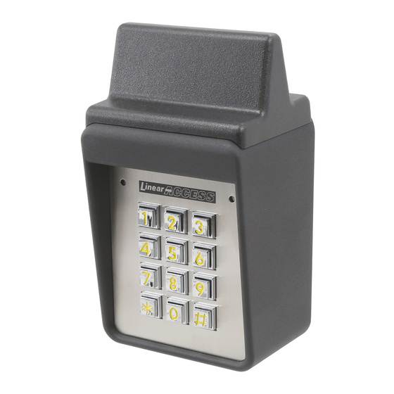
COMPONENT LOCATIONS RED/GREEN POWER/ACCESS INDICATOR NIGHT LIGHT TACTILE KEYPAD YELLOW "LOCKOUT" INDICATOR JUMPER JP2 REMOVE TO RESET MASTER CODE JUMPER JP1 REMOVE TO REDUCE BEEPER SOUND KEYLOCK Figure 1. Component Locations ANTENNA (HIDDEN) TERMINAL BLOCK... -
Page 5: Wiring Diagram
WIRING DIAGRAM TYPICAL GATE INSTALLATION WIRING AKR-1 TERMINALS N.O. MAIN COMMON RELAY N.C. OUTPUT #3 OUTPUT #4 DC OR AC POWER COMMON N.O. AUXILIARY COMMON RELAY N.C. REQUEST-TO-ENTER COMMON INHIBIT EARTH GROUND NOTE: TERMINAL 14 SET FOR INHIBIT REQUIRED WIRING... - Page 6 SECURITY BOLTS AND LOCKNUTS Figure 3. Pedestal Mounting Keypad Backplate Wall Mounting The AKR-1 keypad can be mounted directly to a wall or fl at surface. ❑ Use the appropriate fasteners to secure the keypad’s backplate to the mounting surface.
- Page 7 See the Programming Options section of this manual AKR-1 KEYPAD 2 WIRES FOR REQUEST-TO-ENTER FIRE ACCESS KEYSWITCH 2 WIRES FROM AKR-1 2 WIRES FROM OPERATOR TO TRIGGER GATE OPEN FOR AKR-1 POWER Figure 5. Gate Installation GATE OPERATOR (BEHIND GATE)
- Page 8 COMMON terminals. ☞ NOTE: Either door sense or inhibit can be used. Both features cannot be used at the same time. DOOR SENSE SWITCH 2 WIRES FOR DOOR SENSE AKR-1 KEYPAD 2 WIRES POWER FROM ELECTRIC 2 WIRES POWER DOOR...
-
Page 9: Factory Defaults
Press: The red indicator will light when Programming Mode is exited. ☞ NOTE: The AKR-1 will automatically exit Programming Mode after two minutes of inactivity. Re-entering a Command After a Mistake If the red indicator lights, signaling an incorrect entry, or an incorrect key is pressed... -
Page 10: Programming Options
☞ NOTE: Leading zeros (zeros before the code number, i.e. 0001) do not need to be entered when programming a new entry code. The AKR-1 will internally add any zeros to fi ll all digits determined by the entry code length setting. Leading zeros will have to be entered by the user when entering their code to gain access. - Page 11 Auxiliary Relays in parallel (see the Figure below). Either relay will be able to trigger the access device. Entry codes programmed for the Auxiliary Relay will be able to hold the output on. N.O. MAIN COMMON RELAY N.C. AKR-1 OUTPUTS N.O. AUXILIARY COMMON RELAY N.C. Select Door Sense or Inhibit Input The input on Terminal #14 can be programmed for DOOR SENSE or INHIBIT.
- Page 12 Select Alarm Shunt Output Sets which output activates during the time access is granted. (Use this output to shunt alarm contacts attached to the access door.) This output may be timed or toggled. Press: 1 5 # Output # Output = Output to Activate (0-4) 1 = Relay #1 2 = Relay #2 3 = Output #3, 4 = Output #4 0 = No Output Select Request-to-Enter Output Sets which output activates when the Request-to-Enter input is grounded.
-
Page 13: Radio Programming
Up to four Facility Codes can be entered. The Facility Code number is labeled on the box of block coded transmitters. Enter the Facility Code number (1-15) for each transmitter block added to the AKR-1. Press: 6 0 # Location # Code #... - Page 14 Select Bottom-left Button Output ACT-22 Sets which relay output activates when a transmitter’s bottom-left button is pressed. This setting effects all transmitters used with the AKR-1. See Figure 7 for transmitter button designations for various models. BUTTON 1 = Relay #1 2 = Relay #2 3 = Both Relays 0 = No Output...
- Page 15 Master Reset ✦ CAUTION: Performing a master reset will clear the entire memory of the AKR-1 and return all programmable options to the factory default values. ALL ENTRY CODES AND TRANSMITTERS WILL BE ERASED. STEP 1 Disconnect power from the keypad.
- Page 16 Beeper Sound Level The keypad’s beeper can be set to low or high level. ❑ If the keypad’s beeper is too loud for the keypad’s location, remove jumper JP1 (see Figure 9). REMOVE JUMPER JP1 TO REDUCE THE BEEPER VOLUME Figure 9.
-
Page 17: Akr-1 Operation
AKR-1 OPERATION With Entry Code ❑ Users of the AKR-1 have up to 40 seconds to key in their entry code. ❑ Up to eight seconds are allowed between each keystroke. ❑ All digits of the entry code must be entered. Example: If the code is 0042, the user must enter “0 0 4 2”. -
Page 18: Mgt Obstacle Transmitter Operation
MGT OBSTACLE TRANSMITTER OPERATION One Model MGT obstacle transmitter can be programmed into the AKR-1. The MGT is triggered with a safety edge contact and will activate the AKR-1 Relay #2 for the programmed length of time. ☞ NOTE: If an MGT transmitter is programmed, all other transmitters or entry code activations programmed for Relay #2 will be blocked. -
Page 19: Specifications
fi tness, are valid only until Warranty Expiration Date as labeled on the product. This Linear Corporation Warranty is in lieu of all other warranties express or implied. All products returned for warranty service require a Return Product Authorization Number (RPA#). -
Page 20: Important
IMPORTANT !!! Linear radio controls provide a reliable communications link and fi ll an important need in portable wireless signaling. However, there are some limitations which must be observed. • For U.S. installations only: The radios are required to comply with FCC Rules and Regulations as Part 15 devices.
Need help?
Do you have a question about the AKR-1 and is the answer not in the manual?
Questions and answers