
Related Manuals for Linear ACCESS AK-21


Summary of Contents for Linear ACCESS AK-21
- Page 1 AK-21 Digital Keyless Entry System Installation and Programming Instructions (760) 438-7000 USA & Canada (800) 421-1587 & (800) 392-0123 Toll Free FAX (800) 468-1340 www.linearcorp.com...
-
Page 2: Table Of Contents
LINEAR LIMITED WARRANTY ........6... -
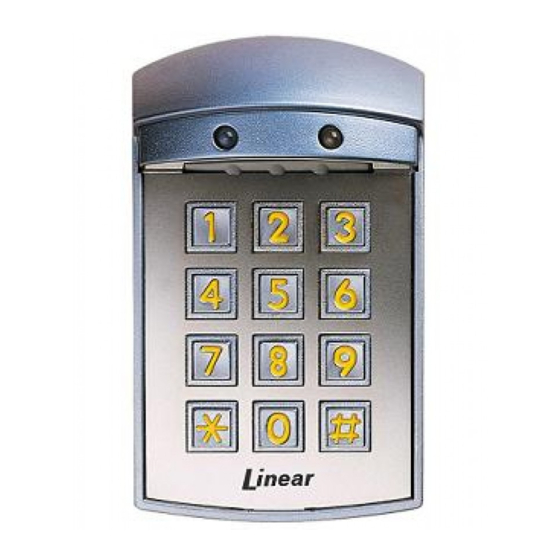
Page 3: Component Locations
COMPONENT LOCATIONS RED/GREEN POWER/ACCESS INDICATOR BEZEL FACEPLATE KEYPAD WIRING DIAGRAM POWER SUPPLY ELECTRIC DOOR STRIKE TO ALARM ALARM SYSTEM CONTACT REQUIRED WIRING NOTES: 1. ALARM SHUNT SET FOR AUXILIARY RELAY OPTIONAL WIRING 2. TERMINAL BLOCK #2, TERMINAL 8 SET FOR DOOR SENSE OTHER WIRING MASTER CODE YELLOW... -
Page 4: Installation
INSTALLATION Before installing the keypad, the unit must be partially disassembled to access the mounting plate. The keypad’s bezel can be exchanged for a different color when the keypad is apart. Opening the Keypad The keypad assembly is secured with two tamper-resistant screws that are hidden behind the keypad’s faceplate. -
Page 5: Keypad Wiring
Keypad Wiring See Figure 7 for an example of a basic door installation. The keypad is mounted adjacent to the door. An electric door strike is mounted in the door jamb to release the door lock. A magnetic switch is mounted on the top of the door jamb for detecting when the door is open. -
Page 6: Factory Defaults
FACTORY DEFAULTS MASTER PROGRAMMING CODE ........123456 ENTRY CODE LENGTH . -
Page 7: Programming Options
PROGRAMMING OPTIONS There are several AK-21 programming options. For most installations, the factory set default options are suffi cient. The keypad must be in Programming Mode to make these changes. Select Door Sense or Inhibit Input The input on Terminal Block TB1, Terminal #8 can be programmed for DOOR SENSE or INHIBIT. -
Page 8: Resetting Keypad
All implied warranties, including implied warranties for merchantability and implied warranties for fi tness, are valid only until Warranty Expiration Date as labeled on the product. This Linear LLC Warranty is in lieu of all other warranties express or implied.
Need help?
Do you have a question about the ACCESS AK-21 and is the answer not in the manual?
Questions and answers