
Related Manuals for Lindy PRO-300


Summary of Contents for Lindy PRO-300
- Page 1 KVM Extender C5 PRO-300 User Manual Tested to Comply with FCC Standards For Commercial Use © LINDY ELECTRONICS LIMITED & LINDY-ELEKTRONIK GMBH - FIRST EDITION (September 2005) LINDY No. 39394 www.lindy.com English...
-
Page 2: About This Manual
If the product should fail to operate correctly in normal use during the warranty period, LINDY will replace or repair it free of charge. Any faulty items are to be returned to LINDY at the owner’s expense. -
Page 3: Table Of Contents
3.4 Keyboard, Video and Mouse connections... 13 3.5 Twisted pair, Power and Serial connections... 13 3.6 Audio connections... 14 4. Operation... 15 4.1 Power and activity indicators... 15 4.2 Locking and unlocking the system... 15 LINDY KVM Extender C5 PRO-300 Installation and Use page 3... - Page 4 6.2 Creating a startup disk... 23 6.3 Reconfiguring the LOCAL connections... 24 6.4 Reconfiguring the REMOTE connections... 25 6.5 Returning all connections to their usual states... 25 7. Troubleshooting... 26 8. Extender C5 Accessories... 27 LINDY KVM Extender C5 PRO-300 Installation and Use page 4...
-
Page 5: Introduction
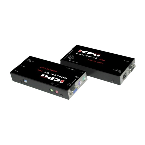
(and also a serial device) up to 300 metres from a system. The LINDY Extender C5 PRO-300 set consists of two modules: a local module that attaches to your computer system and a remote module to which the peripherals are connected. The long distance link between the two modules is made via Category 5, or higher, twisted pair cabling. -
Page 6: Supplied Items
English Manual 1.1 Supplied items Optional Power supply input Power and signal activity indicator Power and signal activity indicator LINDY KVM Extender C5 PRO-300 Installation and Use page 6... -
Page 7: Installation
The installation of the Extender C5 set is straightforward and can best be achieved in most cases by following these stages for each module: • Check or set the configuration switch settings • Mount the module • Connect the cables LINDY KVM Extender C5 PRO-300 Installation and Use page 7... -
Page 8: Extender C5 Configuration Switch Settings
Set transparent mode. Use this setting if the Extender C5 modules are to be used with KVM switches that are not manufactured by LINDY Electronics. Cascaded KVM switches often use special signals to set or identify conditions. In transparent mode, the Extender C5 modules will pass the signals without attempting to interpret them. - Page 9 2 OFF Hotkeys = ALT and SHIFT 3 ON 2 ON Hotkeys = CTRL and ALT 3 OFF 2 ON Hotkeys disabled 3 ON REMOTE Switch 4 Reserved for future use LINDY KVM Extender C5 PRO-300 Installation and Use page 9...
-
Page 10: Mounting The Extender C5 Module
For correct operation, the local and remote units must have ground connections: At the computer end, ensure that the computer or KVM switch that the LOCAL module is connected to has a ground connection. At the keyboard/monitor/mouse end, ensure that the REMOTE module’s power supply is connected to a grounded power outlet. -
Page 11: Connections
Monitor Keyboard Mouse Speaker Microphone LINDY KVM Extender C5 PRO-300 Installation and Use Blue Purple Mid green Light green Pink (or maroon) page 11... -
Page 12: Serial Cable Connection
If the keyboard connection will not be used then you will need to use an external power supply of the same type used for the REMOTE module. These are available from your LINDY supplier. LINDY KVM Extender C5 PRO-300 Installation and Use page 12... -
Page 13: Connections At The Remote Module
Connect the other end of the power lead into a nearby mains socket. If the serial connection to be used, attach the lead from your serial device to the 9 way male connector on the REMOTE module. LINDY KVM Extender C5 PRO-300 Installation and Use page 13... -
Page 14: Audio Connections
Note: The microphone input has a dual function whereby it can either support a mono-channel microphone or alternatively receive stereo line input. Switch 3 on the LOCAL module controls the setting of this port: LOCAL switch 3 OFF - microphone, LOCAL switch 3 ON - stereo line in. -
Page 15: Operation
The screen will go blank and the three keyboard indicators will begin alternately flashing between the ’Num Lock’ and ’Scroll Lock’, and ’Caps Lock’. This sequence indicates that a password is required. LINDY KVM Extender C5 PRO-300 Installation and Use page 15... -
Page 16: Special Configuration
Hotkeys = <CTRL> and <SHIFT> (default setting) 3 OFF 2 OFF Hotkeys = <ALT> and <SHIFT> 3 ON 2 ON Hotkeys = <CTRL> and <ALT> 3 OFF 2 ON Hotkeys disabled 3 ON LINDY KVM Extender C5 PRO-300 Installation and Use page 16... -
Page 17: Configuration Mode
Press <RETURN> once more to exit configuration mode. For full details about how to lock and unlock the system using your password, please see section 4.2 ‘Locking and unlocking the system.’ LINDY KVM Extender C5 PRO-300 Installation and Use page 17... -
Page 18: Password Override
5.6 Hot plugging and mouse restoration It is strongly recommended that you switch off the computer system before attempting to connect it via the Extender C5 modules. However, if this is not possible then you need to ‘hot plug’ the Extender C5 modules while power is still applied to the system. - Page 19 <RETURN> to enter configuration mode. Enter the appropriate protocol code: • Microsoft compatible – press <M> <3> <RETURN> • Logitech compatible – press <M> <4> <RETURN> To exit configuration mode, press <RETURN> LINDY KVM Extender C5 PRO-300 Installation and Use page 19...
-
Page 20: Video Compensation, Image Controls - Sharpness And Brightness
The new compensation setting will be stored, even when power is removed or if a complete reset is initiated. The setting should not require further changes unless the cabling arrangement is altered. LINDY KVM Extender C5 PRO-300 Installation and Use page 20... - Page 21 <SHIFT> along with <RETURN>) to enter configuration mode. The three keyboard indicators (‘Num Lock’, ‘Caps Lock’ and ‘Scroll Lock’) will now begin to flash in sequence. LINDY KVM Extender C5 PRO-300 Installation and Use Please see the next section for details. page 21...
-
Page 22: The Skew Compensation Adjustment
Reset all configuration options to default states – <F> <8> <RETURN> Returns all user configurable options to the settings that are installed at manufacture. The password will be cleared; however, the current video compensation setting will not be reset. LINDY KVM Extender C5 PRO-300 Installation and Use page 22... -
Page 23: Flash Upgrade Procedure
• Return all connections to their usual states 6.1 Get the upgrade files from LINDY Technical Support Please contact the LINDY Support team in your country by email, telephone or contact form from the LINDY website. See www.LINDY.com for all LINDY offices and contact information world wide. -
Page 24: Reconfiguring The Local Connections
On the computer from which you will run the upgrade, ensure that its BIOS settings will allow it to boot from the floppy disk drive, rather than booting immediately from the hard drive. Switch off the computer and disconnect the twisted pair cable from the LOCAL module. On the KVM+A multi-cable, leave the keyboard connector attached to the keyboard port of the computer. -
Page 25: Reconfiguring The Remote Connections
Once the upgrade process has been completed, perform the following to return the system to its previous state. Ensure that switch 1 on both the LOCAL and REMOTE modules is set to the OFF positions. Refer to section 3 ‘Connections’ for detailed instructions on correctly connecting the LOCAL and REMOTE modules to the computer, its peripherals, the REMOTE power supply and the twisted-pair cable. -
Page 26: Troubleshooting
The mouse connection may have been interrupted. Either, reboot the system and re-power the REMOTE module power supply, or try using the mouse restoration command. Please refer to section 5.6 ‘Hot plugging and mouse restoration.’ LINDY KVM Extender C5 PRO-300 Installation and Use page 26... -
Page 27: Extender C5 Accessories
Sound input from the stereo line input is distorted and only one channel is working • Check the setting of LOCAL switch 3 – if a stereo line input is connected at the REMOTE module, the switch should be set to ON. - Page 28 Radio Frequency Energy and Compliance Declaration A Category 5 (or better) twisted pair cable must be used to connect the LINDY Extender C5 units in order to maintain compliance with radio frequency energy emission regulations and ensure a suitably high level of immunity to electromagnetic disturbances.
Need help?
Do you have a question about the PRO-300 and is the answer not in the manual?
Questions and answers