
Related Manuals for Abus TVAC18000B


Summary of Contents for Abus TVAC18000B
- Page 1 TVAC18000B User guide Betjeningsvejledning Instrukcja obsługi Manual de instrucciones Bruksanvisning Инструкция по эксплуатации Version 10/2014...
- Page 2 English This user guide contains important information on starting operation and using the device. Make sure that this user guide is handed over when the product is given to other persons. Keep this user guide to consult later. For a list of contents with the corresponding page numbers, see page 5. Polski Niniejsza instrukcja obsługi zawiera ważne wskazówki dotyczące uruchamiania i obsługi.
-
Page 3: User Guide
TVAC18000B User guide Version 10/2014 English translation of the original German user guide Retain for future reference! - Page 4 ABUS Security-Center GmbH is not liable or responsible for direct or indirect damage resulting from the equipment, performance and use of this product. No forms of guarantee are accepted for the contents of this...
- Page 5 English Explanation of symbols The triangular high voltage symbol is used to warn of the risk of injury or health hazards (e.g. caused by electric shock). The triangular warning symbol indicates important notes in these operating instructions which must be observed. This symbol indicates special tips and notes on the operation of the unit.
- Page 6 English Wireless transmission The wireless range depends on a variety of environmental factors. The local conditions at the installation site may have a negative impact on the range. When there are no obstructions between the receiver and transmitter, a range of up to 150 m is possible, but this range will be considerably less within buildings. The following environmental conditions compromise both the range as well as the frame rate: Mobile communication masts, high-tension pylons, electrical wires, ceilings and walls, devices with the same or an adjacent wireless frequency.
-
Page 7: Table Of Contents
English Contents Intended use ............................... 6 Scope of delivery ............................6 Features and functions ..........................7 Information and FAQs ..........................7 Device description ............................. 7 5.1 Recorder description .......................... 7 5.2 Camera description ..........................8 Installation..............................9 6.1 Recorder installation .......................... 9 6.2 Connecting an external hard disk drive .................. -
Page 8: Intended Use
4x view on the monitor / TV, as well as recording with QVGA resolution at the same time. You can also view the live view from the camera via smartphone using the “TVAC18000” ABUS app and play recorded data as well as configure the recorder. -
Page 9: Features And Functions
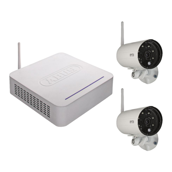
Can be extended to include up to four wireless cameras 4. Information and FAQs You can find important information and FAQs about this and other products on the website www.abus.com/plug-and-play. You will find information for troubleshooting under item 11 of these instructions. 5. Device description 5.1 Recorder description... -
Page 10: Camera Description
English Rear view HDMI port Video & audio output on monitor/TV 2 x USB Connections for mouse and external hard disk drive RJ45 connection LAN interface for internet connection ... -
Page 11: Installation
English Rear view SMA connector Microphone Pairing button Power supply connection 6. Installation 6.1 Recorder installation Monitor / TV Mouse Mobile end Recorder device Router Internet Cameras 1. Screw the antenna on to the recorder and plug in the mouse to a USB port. 2. -
Page 12: Connecting An External Hard Disk Drive
English 6.2 Connecting an external hard disk drive First, connect a mouse (not included) to one of the USB ports. Then connect an external hard disk drive to the second USB port. Please format this before initial installation. Recommended format: FAT32 Connect the power supply only after you have connected all the USB devices. -
Page 13: Mounting The Camera
English 6.4 Mounting the camera Use the camera mount to help you find a suitable place for installation. Use the drill holes to mark the surface then drill the holes. Insert the wall plugs supplied before you attach the bracket with the screws. Note: Before you begin installing, make sure that the wireless transmission range is adequate at the site of the required installation. -
Page 14: Pairing The Camera To The Recorder
English 6.5 Pairing the camera to the recorder To connect a camera with the recorder, proceed as follows: 1. Connect the camera and the recorder to the power supply. 2. In the recorder menu, select “Camera”, then “Pairing” and the required camera (1–4). - Page 15 English Adding the system Open the app on your mobile phone and select the device in the list. Click on “new” or “+” to add a new system. Entering system information 1. Enter a name for your system at “Name” which should then be displayed on your mobile phone.
- Page 16 English Connection status If you have added your system successfully, the name of your system and the name of your system and the corresponding DID appear in the selection list. Click on the name to go to the live view. Press the Play button to start the live view.
- Page 17 English System settings: Date & time Language Display Idle display Power saving Storage management: Storage status Storage format Network settings Network information You can find a description of each menu item in “8. Operating the recorder”.
-
Page 18: Operating The Recorder
English 8. Operating the recorder To switch the recorder ON or OFF, press the power button on the back of the recorder. 8.1 Live view The live view starts automatically after the device is switched on in the quad view. To show a camera as full-screen, left-click with the mouse on the required channel. - Page 19 English Smart-Quad view: In the smart-quad view, click on the required channel to display this on the left in large view. To display a channel in full screen it must be shown in large view. To do this, click on the picture in large view and click again to return to the smart-quad view. Dynamic view: You can configure the view dynamically here.
-
Page 20: Main Menu
English 8.2 Main menu Description Sub menu items Pairing Activation Camera settings Resolution Quality Schedule Motion sensitivity Recording Motion area Detection Display of event list in calendar format Playback/event list Date &... -
Page 21: Camera Settings
English 8.2.1 Camera settings Menu item Description Pairing the camera is necessary to establish a connection. The connection stays once it has been set up. If you want to change the camera to another channel, you need to pair it again. In the recorder menu, select “Camera”, then “Pairing a new camera”... -
Page 22: Recording
English 8.2.2 Recording Menu item Description Select a camera or all the cameras for the schedule. 1. Select one of the cameras 1-4. You can now select the recording type, the day of the week and the time period. 2. Select all the cameras to activate the schedule for all cameras. Motion detection: Recording starts if motion is detected. - Page 23 English You can make the settings for the motion sensitivity here. The motion sensitivity can be controlled via the PIR sensor as well as the PIR sensor and the software motion detection at the same time. PIR motion detection: Motion is detected only by the camera's PIR sensor.
-
Page 24: Event List
English 8.2.3 Event list All the recordings are displayed in the event list and are sorted according to the date. You can navigate to the required schedule using the arrow buttons. Select the required camera. You can also display the events of all the cameras. A field with a coloured background means that a recording is available on this day. -
Page 25: System Settings
English 8.2.4 System settings Menu item Description Use the arrow keys to set the date and time. Date & time Right-click on the mouse to save the settings and exit the menu. Select the language for your system. Language The system is then reset to the factory settings. Select the settings display for the live view here. -
Page 26: Storage Management
English 8.2.5 Storage management Menu item Description Activate/deactivate the cyclical storage function for the hard disk Storage drive or SD card. management Formatting the hard disk drive or SD card. Format When formatting, all the recorded data is deleted. To establish a connection with the internet and so that you can access the recorder with the app, connect it to your router using the network cable. - Page 27 English Network connectivity is shown with the following icons. Network connection available No network connection exists. Check whether the recorder is connected with the router. System information display: Recorder firmware version Camera firmware versions Network information Security code ...
-
Page 28: Maintenance And Cleaning
English 9. Maintenance and cleaning 9.1 Maintenance Regularly check the technical safety of the product, e.g. check the housing for damage. If it seems that it may no longer be possible to operate the device safely, stop using the product and protect it from unintentional use. -
Page 29: Tips For Troubleshooting
English 11. Tips for troubleshooting Questions Answers What does pairing the Pairing creates the exclusive, encrypted wireless connection recorder and camera between the recorder and camera. mean and how does this To connect a camera with the recorder, proceed as follows: work? 1. -
Page 30: Technical Data
English 12. Technical data Camera Recorder Number of IR LEDs Display option Full-screen, Quad, Smart Quad Resolution 640 x 480 pixels 720p (HD) Recording options Schedule, motion detection, manual Image sensor ¼" CMOS Angle of view 55° (horizontal) / 44° (vertical) Frequency 2.4 GHz Inside max.
Need help?
Do you have a question about the TVAC18000B and is the answer not in the manual?
Questions and answers