Honeywell Hyperion 1300G User Manual
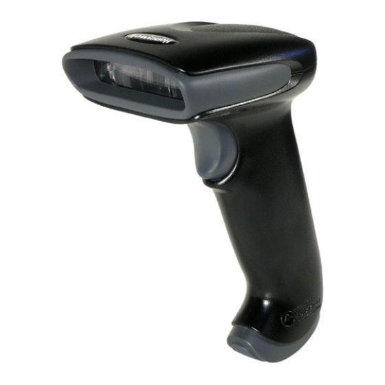
General purpose handheld linear scanner
Hide thumbs
Also See for Hyperion 1300G:
- User manual (188 pages) ,
- Quick start manual (13 pages) ,
- Get started (3 pages)
Table of Contents
Advertisement
Advertisement
Table of Contents

Related Manuals for Honeywell Hyperion 1300G


Summary of Contents for Honeywell Hyperion 1300G
- Page 1 Hyperion 1300g General Purpose Handheld Linear Scanner User’s Guide ™...
- Page 2 Disclaimer Honeywell International Inc. (“HII”) reserves the right to make changes in speci- fications and other information contained in this document without prior notice, and the reader should in all cases consult HII to determine whether any such changes have been made. The information in this publication does not repre- sent a commitment on the part of HII.
-
Page 3: Table Of Contents
USB HID POS ............2-5 USB Serial Commands ..........2-5 USB Serial Emulation..........2-5 CTS/RTS Emulation ..........2-6 ACK/NAK Mode............. 2-6 Honeywell Bioptic Aux Port Configuration....2-6 ® Datalogic™ Magellan Bioptic Aux Port Configuration 2-7 Wincor Mode A............2-7 Keyboard Country Layout ........... 2-8 Keyboard Mode Options ........... - Page 4 RS232 Modifiers ............2-22 RS-232 Baud Rate..........2-22 RS-232 Word Length: Data Bits, Stop Bits, and Parity 2-23 RS-232 Handshaking..........2-24 RS232 Timeout ............ 2-27 XON/XOFF ............2-27 ACK/NAK ............. 2-27 Scanner to Bioptic Communication......2-28 Scanner-Bioptic Packet Mode ......2-28 Chapter 3 - Input/Output Settings Good Read Indicators..........
- Page 5 Output Sequence Overview ........3-10 To Add an Output Sequence....... 3-10 Other Programming Selections ......3-10 Output Sequence Editor ........3-11 Output Sequence Editor ........3-13 Require Output Sequence........3-13 Multiple Symbols ............3-13 No Read ..............3-14 Video Reverse............3-15 Chapter 4 - Data Editing Prefix/Suffix Overview ..........
- Page 6 Data Format Editor Commands ........5-4 Send Commands ........... 5-4 Move Commands........... 5-7 Search Commands ..........5-8 Miscellaneous Commands........5-10 Data Format Editor ..........5-14 Data Formatter............. 5-14 Chapter 6 - Symbologies Introduction ..............6-1...
- Page 7 All Symbologies............6-2 Codabar Start/Stop Characters ......6-3 Codabar Check Character........6-4 Codabar Concatenation ........6-5 Codabar Message Length ........6-6 Code 39 Start/Stop Characters......6-7 Code 39 Check Character........6-7 Code 39 Message Length ........6-8 Code 39 Append ........... 6-8 Full ASCII ............
- Page 8 UPC E0 Addenda ..........6-31 EAN/JAN 13 Check Digit ........6-32 EAN/JAN 13 Addenda ......... 6-33 EAN/JAN 13 Addenda Required......6-33 EAN/JAN 13 Addenda Separator ......6-34 ISBN Translate ............ 6-34 EAN/JAN 8 Check Digit ........6-35 EAN/JAN 8 Addenda ........... 6-36 EAN/JAN 8 Addenda Required......
- Page 9 Trigger Commands ............. 9-4 Resetting the Standard Product Defaults ....9-4 Menu Commands ............9-5 Chapter 10 - Product Specifications Hyperion 1300g Product Specifications ....10-1 Standard Connector Pinouts ........10-2 Chapter 11 - Maintenance Repairs ..............11-1 Maintenance.............. 11-1 Cleaning the Device ..........
- Page 10 viii...
-
Page 11: Chapter 1 - Getting Started
Hyperion 1300g. Product specifications, dimensions, warranty, and customer support information are also included. Honeywell bar code scanners are factory programmed for the most common terminal and communications settings. If you need to change these settings, programming is accomplished by scanning the bar codes in this guide. -
Page 12: Connecting With Keyboard Wedge
3. Verify the scanner operation by scanning a bar code from the Sample Symbols in the back of this manual. For additional USB programming and technical information, refer to the Honey- well “USB Application Note,” available at www.honeywellaidc.com. Connecting with Keyboard Wedge A scanner can be connected between the keyboard and PC as a “keyboard wedge,”... -
Page 13: Connecting With Rs-232 Serial Port
Connecting with RS-232 Serial Port 1. Turn off power to the terminal/computer. 2. Connect the appropriate interface cable to the scanner. only if power supply is included 3. Plug the serial connector into the serial port on your computer. Tighten the two screws to secure the connector to the port. -
Page 14: Reading Techniques
1. Connect the appropriate interface cable to the device, then to the computer. 2. Turn the terminal/computer power back on. The scanner beeps. 3. Verify the scanner operation by scanning a bar code from the Sample Symbols in the back of this manual. The scanner beeps once. 4. -
Page 15: Menu Bar Code Security Settings
Menu Bar Code Security Settings Honeywell scanners are programmed by scanning menu bar codes or by send- ing serial commands to the scanner. If you want to restrict the ability to scan menu codes, you can use the Menu Bar Code Security settings. - Page 16 Serial Programming Commands starting on page 9-1 lists the factory default settings for each of the commands (indicated by an asterisk (*) on the programming pages). 1 - 6...
-
Page 17: Chapter 2 - Programming The Interface
Programming the Interface Introduction This chapter describes how to program your system for the desired interface. Programming the Interface - Plug and Play Plug and Play bar codes provide instant scanner set up for commonly used interfaces. Note: After you scan one of the codes, power cycle the host terminal to have the interface in effect. -
Page 18: Rs232 Serial Port
RS232 Serial Port The RS232 Interface bar code is used when connecting to the serial port of a PC or terminal. The following RS232 Interface bar code also programs a car- riage return (CR) and a line feed (LF) suffix, baud rate, and data format as indi- cated below. -
Page 19: Opos Mode
Each bar code above also programs the following suffixes for each symbology: Symbology Suffix Symbology Suffix EAN 8 Code 39 00 0A 0B EAN 13 Interleaved 2 of 5 00 0D 0B UPC A Code 128 * 00 0A 0B UPC E Code 128 ** 00 18 0B... -
Page 20: Usb Ibm Surepos
OPOS Mode USB IBM SurePos Scan the following “Plug and Play” codes to program the scanner for an IBM SurePos (USB handheld scanner) interface. Note: After scanning the code below, you must power cycle the cash register. USB IBM SurePos (USB Handheld Scanner) Interface USB IBM SurePos... -
Page 21: Usb Pc Or Macintosh Keyboard
Scan the following code to program the scanner to emulate a regular RS232- based COM Port. If you are using a Microsoft® Windows® PC, you will need to download a driver from the Honeywell website (www.honeywellaidc.com). The driver will use the next available COM Port number. Apple® Macintosh comput- ers recognize the scanner as a USB CDC class device and automatically uses a class driver. -
Page 22: Cts/Rts Emulation
* ACK/NAK Mode Off Honeywell Bioptic Aux Port Configuration Scan the following Plug and Play code to program the scanner for a Honeywell bioptic scanner auxiliary port configuration. This bar code sets the baud rate to 38400 bps and the data format to 8 data bits, no parity, 1 stop bit. Character RTS/CTS with timeout and 232 ACK/NAK are also enabled. -
Page 23: Datalogic™ Magellan
® Datalogic™ Magellan Bioptic Aux Port Configuration Scan the following Plug and Play code to program the scanner for a Datalogic Magellan bioptic scanner auxiliary port configuration. This bar code sets the baud rate to 9600 bps and the data format to 8 data bits, no parity, 1 stop bit. Datalogic Magellan Bioptic Settings Note: If you are having unexpected results with this programming code, scan Resetting the Custom Defaults... -
Page 24: Keyboard Country Layout
Keyboard Country Layout Scan the appropriate country code below to program the keyboard layout for your country or language. As a general rule, the following characters are sup- ported, but need special care for countries other than the United States: @ | $ # { } [ ] = / ‘... - Page 25 Brazil Brazil (MS) Bulgaria (Cyrillic) Bulgaria (Latin) Canada (French legacy) Canada (French) Canada (Multilingual) China Croatia 2 - 9...
- Page 26 Czech Czech (Programmers) Czech (QWERTY) Czech (QWERTZ) Denmark Dutch (Netherlands) Estonia Faroese Finland 2 - 10...
- Page 27 France Gaelic Germany Greek Greek (220 Latin) Greek (220) Greek (319 Latin) Greek (319) Greek (Latin) 2 - 11...
- Page 28 Greek (MS) Greek (Polytonic) Hebrew Hungarian (101 key) Hungary Iceland Ireland Italian (142) Italy 2 - 12...
- Page 29 Japan ASCII Kazakh Korea Kyrgyz (Cyrillic) Latin America Latvia Latvia (QWERTY) Lithuania Lithuania (IBM) 2 - 13...
- Page 30 Macedonia Malta Mongolian (Cyrillic) Norway Poland Polish (214) Polish (Programmers) Portugal Romania 2 - 14...
- Page 31 Russia Russian (MS) Russian (Typewriter) Serbia (Cyrillic) Serbia (Latin) Slovakia Slovakia (QWERTY) Slovakia (QWERTZ) 2 - 15...
- Page 32 Slovenia Spain Spanish variation Sweden Switzerland (French) Switzerland (German) Tatar Thailand Turkey F 2 - 16...
- Page 33 Turkey Q Ukrainian United Kingdom United Stated (Dvorak right) United States (Dvorak left) United States (Dvorak) United States (International) Uzbek (Cyrillic) Vietnam 2 - 17...
-
Page 34: Keyboard Mode Options
Keyboard Mode Options ALT Mode If your bar code contains special characters from the extended ASCII chart for example, an e with an accent grave (è), you will use ALT Mode. (See Extended ASCII Characters on page A-6.) Note: Scan the ALT mode bar code after scanning the appropriate Keyboard Country code. -
Page 35: Keyboard Modifiers
Shift Lock is used when you normally have the Shift Lock key on (not common to U.S. keyboards). Shift Lock Automatic Caps Lock is used if you change the Caps Lock key on and off. The software tracks and reflects if you have Caps Lock on or off (AT and PS/2 only). - Page 36 mode, and it does not support all keyboard country codes. New users should use the Windows mode. Refer to Keyboard Function Relationships, page 7-1 for CTRL+ X Values. Windows Mode Prefix/Suffix Off: The scanner sends key combinations for ASCII control characters for values 00-1F (refer to ASCII Conversion Chart (Code Page 1252) on page A-3 for non-reprintable characters), but it does not...
- Page 37 Numeric Keypad Mode: Sends numeric characters as if entered from a numeric keypad. Default = Off Numeric Keypad Mode On * Numeric Keypad Mode Off Automatic Direct Connect Mode: This selection can be used if you have an IBM AT style terminal and the system is dropping characters. Default = Off Automatic Direct Connect Mode On * Automatic Direct Connect...
-
Page 38: Rs232 Modifiers
RS232 Modifiers RS-232 Baud Rate Baud Rate sends the data from the scanner to the terminal at the specified rate. The host terminal must be set for the same baud rate as the scanner. Default = 38,400. 1200 2400 4800 9600 19200 2 - 22... -
Page 39: Rs-232 Word Length: Data Bits, Stop Bits, And Parity
* 38400 57,600 115,200 RS-232 Word Length: Data Bits, Stop Bits, and Parity Data Bits sets the word length at 7 or 8 bits of data per character. If an applica- tion requires only ASCII Hex characters 0 through 7F decimal (text, digits, and punctuation), select 7 data bits. -
Page 40: Rs-232 Handshaking
7 Data, 1 Stop, Parity Odd 7 Data, 2 Stop Parity None 7 Data, 2 Stop, Parity Even 7 Data, 2 Stop, Parity Odd * 8 Data, 1 Stop, Parity None 8 Data, 1 Stop, Parity Even 8 Data, 1 Stop, Parity Odd RS-232 Handshaking RS232 Handshaking allows control of data transmission from the scanner using software commands from the host device. - Page 41 RTS/CTS Off, RTS Inactive: RTS/CTS is turned off so no data flow control is used and RTS is inactive. Flow Control, No Timeout: The scanner asserts RTS when it has data to send, and will wait indefinitely for CTS to be asserted by the host. Character-Based Flow Control, No Timeout: The scanner asserts RTS when it has a character to send, and will wait indefinitely for CTS to be asserted by the host...
- Page 42 Character-Based Flow Control, No Timeout Two-Direction Flow Control Flow Control with Timeout Character-Based Flow Control with Timeout CTS-Based Flow Control, No Timeout RTS On No RTS if CTS is On 2 - 26...
-
Page 43: Rs232 Timeout
RS232 Timeout When using Flow Control with Timeout, you must program the length of the delay you want to wait for CTS from the host. Set the length (in milliseconds) for a timeout by scanning the bar code below, then setting the timeout (from 1- 65535 milliseconds) by scanning digits from the inside back cover, then scan- ning Save. -
Page 44: Scanner To Bioptic Communication
ACK/NAK On * ACK/NAK Off Scanner to Bioptic Communication The following settings are used to set up communication between Honeywell scanners and bioptic scanners. Note: The scanner’s baud rate must be set to 38400 and the RS232 timeout must be set to 3000 in order to communicate with a bioptic scanner. See "RS232 Modifiers"... -
Page 45: Chapter 3 - Input/Output Settings
Input/Output Settings Good Read Indicators Beeper – Good Read The beeper may be programmed On or Off in response to a good read. Turning this option off, only turns off the beeper response to a good read indication. All error and menu beeps are still audible. Default = On. * On Beeper Volume –... -
Page 46: Beeper Pitch - Good Read
Beeper Pitch – Good Read The beeper pitch codes modify the pitch (frequency) of the beep the scanner emits on a good read. Default = Medium Low (1600 Hz) * Medium (2750 Hz) High (4200 Hz) Beeper Duration – Good Read The beeper duration codes modify the length of the beep the scanner emits on a good read. -
Page 47: Beeper Pitch - Error
Beeper Pitch – Error The beeper pitch codes modify the pitch (frequency) of the sound the scanner emits when there is a bad read or error. Default = 100 Hz. * Razz (100 Hz) * Medium (2000 Hz) High (4200 Hz) LED –... -
Page 48: Good Read Delay
LED flashes are in sync with one another. To change the number of beeps, scan the bar code below and then scan a digit (1-9) bar code and the Save bar code on the inside the back cover of this manual. Default = One. Number of Pulses Good Read Delay This sets the minimum amount of time before the scanner can read another bar... -
Page 49: Trigger Modes
Trigger Modes Manual/Serial Trigger You can activate the scanner either by pressing the trigger, or using a serial trig- ger command (see Trigger Commands on page 9-4). When in manual trigger mode, the scanner scans until a bar code is read, or until the trigger is released. When in serial mode, the scanner scans until a bar code has been read or until the deactivate command is sent. -
Page 50: Presentation Mode
Presentation Mode Presentation Mode uses ambient light to detect bar codes. The LEDs are off for ambient conditions until a change occurs in the scanner’s field of view. Then the LEDS turn on automatically to read the code. If the light level in the room is not high enough, Presentation Mode may not work properly. -
Page 51: Reread Delay
Scan the Hands Free Time-Out bar code, then scan the time-out duration (from 0-300,000 milliseconds) from the inside back cover, and Save. Default = 5,000 ms. Hands Free Time-Out Reread Delay This sets the time period before the scanner can read the same bar code a sec- ond time. -
Page 52: User-Specified Reread Delay
User-Specified Reread Delay If you want to set your own length for the reread delay, scan the bar code below, then set the delay (from 0-30,000 milliseconds) by scanning digits from the inside back cover, then scanning Save. User-Specified Reread Delay Centering Use Centering to narrow the scanner’s field of view to make sure the scanner reads only those bar codes intended by the user. - Page 53 Centering On * Centering Off Left of Centering Window Right of Centering Window 3 - 9...
-
Page 54: Output Sequence Overview
Output Sequence Overview Output Sequence Editor This programming selection allows you to program the scanner to output data (when scanning more than one symbol) in whatever order your application requires, regardless of the order in which the bar codes are scanned. Reading the Default Sequence symbol programs the scanner to the Universal values, shown below. -
Page 55: Output Sequence Editor
Output Sequence Editor Enter Sequence Default Sequence Output Sequence Example In this example, you are scanning Code 93, Code 128, and Code 39 barcodes, but you want the image scanner to output Code 39 1st, Code 128 2nd, and Code 93 3rd, as shown below. Note: Code 93 must be enabled to use this example. - Page 56 start character match for Code 128, 42h = “B” termination string for second code code identifier for Code 93 9999 code length that must match for Code 93, 9999 = all lengths start character match for Code 93, 43h = “C” termination string for third code To program the previous example using specific lengths, you would have to count any programmed prefixes, suffixes, or formatted characters as part of the...
-
Page 57: Require Output Sequence
Output Sequence Editor Enter Sequence Default Sequence Require Output Sequence When an output sequence is Required, all output data must conform to an edited sequence or the image scanner will not transmit the output data to the host device. When it’s On/Not Required, the image scanner will attempt to get the output data to conform to an edited sequence, but if it cannot, the image scanner transmits all output data to the host device as is. -
Page 58: No Read
beeping (if turned on) for each read. The scanner attempts to find and decode new symbols as long as the trigger is pulled. When this programming selection is turned Off, the scanner will only read the symbol closest to the aiming beam. * Off No Read With No Read turned On, the scanner sends an “NR”... -
Page 59: Video Reverse
Video Reverse Video Reverse is used to allow the scanner to read bar codes that are inverted. The “Off” bar code below is an example of this type of bar code. Note: If additional menuing is required, Video Reverse must be disabled to read the menu bar codes and then re-enabled after menuing is completed. - Page 60 3 - 16...
-
Page 61: Chapter 4 - Data Editing
Data Editing Prefix/Suffix Overview When a bar code is scanned, additional information is sent to the host computer along with the bar code data. This group of bar code data and additional, user-defined data is called a “message string.” The selections in this section are used to build the user-defined data into the message string. -
Page 62: To Add A Prefix Or Suffix
To Add a Prefix or Suffix Step 1. Scan the Add Prefix or Add Suffix symbol (page 4-3). Step 2. Determine the 2 digit Hex value from the Symbology Chart (included in Appendix A) for the symbology to which you want to apply the prefix or suffix. -
Page 63: To Add A Carriage Return Suffix To All Symbologies4
Step 1. Scan the Clear One Prefix or Clear One Suffix symbol. Step 2. Determine the 2 digit Hex value from the Symbology Chart (included in Appendix A) for the symbology from which you want to clear the prefix or suffix. Step 3. -
Page 64: Suffix Selections
Suffix Selections Add Suffix Clear One Suffix Clear All Suffixes Transmit Alternate Extended ASCII Characters You may need to emulate special keyboard functions, such as up or down arrows, Alt/Make or Alt/Break commands, that are not supported in the Extended ASCII Character table. Refer to Alternate Extended ASCII Charac- ters (page 4-5) for a range of keyboard function keys and corresponding deci-... - Page 65 Alternate Extended ASCII Characters DEC HEX Keyboard Function DEC HEX Keyboard Function ↑ 128 80 152 98 up arrow ↓ 129 81 153 99 down arrow → 130 82 154 9A right arrow ← 131 83 155 9B left arrow 132 84 Insert 156 9C Numeric Keypad +...
-
Page 66: Function Code Transmit
Function Code Transmit When this selection is enabled and function codes are contained within the scanned data, the scanner transmits the function code to the terminal. Charts of these function codes are provided in Supported Interface Keys starting on page 7-2. -
Page 67: Intercharacter Delay
Intercharacter Delay An intercharacter delay of up to 495 milliseconds may be placed between the transmission of each character of scanned data. Scan the Intercharacter Delay bar code below, then scan the number of steps in 5 millisecond incre- ments and the Save bar code using the inside the back cover of this manual. Prefix Scanned Data Suffix... -
Page 68: Interfunction Delay
To remove this delay, scan the Delay Length bar code, and set the number of steps to 0. Scan the Save bar code using the inside the back cover of this manual. Interfunction Delay An interfunction delay of up to 495 milliseconds may be placed between the transmission of each control character in the message string. - Page 69 To remove this delay, scan the Intermessage Delay bar code, then set the number of steps to 0. Scan the Save bar code using the inside the back cover of this manual. 4 - 9...
- Page 70 4 - 10...
-
Page 71: Chapter 5 - Data Formatting
Data Formatting Data Format Editor Introduction You may use the Data Format Editor to change the scanner’s output. For exam- ple, you can use the Data Format Editor to insert characters at certain points in bar code data as it is scanned. The selections in the following pages are used only if you wish to alter the output. -
Page 72: Other Programming Selections
Step 3. Terminal Type Refer to the Supported Terminals Chart (page 5-4) and locate the Ter- minal ID number for your PC. Scan three numeric bar codes on the inside back cover to program the scanner for your terminal ID (you must enter 3 digits). - Page 73 data length for the specific data format that you want to delete. All other formats remain unaffected. • Save from the inside the back cover of this manual This exits, saving any Data Format changes. • Discard from the inside the back cover of this manual This exits without saving any Data Format changes.
-
Page 74: Interface / Terminal Id Table
Interface / Terminal ID Table Interface Terminal ID PC keyboard (HID) Mac Keyboard PC Keyboard (Japanese) Serial (COM driver required) HID POS USB SurePOS Handheld USB SurePOS Tabletop Serial RS232 TTL RS232 True RS485 (IBM-HHBCR 1+2, 46xx) Keyboard PS2 compatibles AT compatibles Data Format Editor Commands When working with the Data Format Editor, a virtual cursor is moved along your... - Page 75 F2 Example: Send a number of characters Send the first 10 characters from the bar code above, followed by a carriage return. Command string: F2100D F2 is the “Send a number of characters” command 10 is the number of characters to send 0D is the hex value for a CR The data is output as: 1234567890 F2 and F1 Example: Split characters into 2 lines...
- Page 76 The data is output as: 1234567890AB <tab><tab> Insert symbology name B3 Insert the name of the bar code’s symbology in the output message, without moving the cursor. Only symbologies with a Honeywell ID are included (see Symbology Charts on page A-1). Refer to the...
-
Page 77: Move Commands
Insert bar code length B4 Insert the bar code’s length in the output message, without moving the cursor. The length is expressed as a numeric string and does not include leading zeroes. B3 and B4 Example: Insert the symbology name and length Send the symbology name and length before the bar code data from the bar code above. -
Page 78: Search Commands
03 is the number of characters to move the cursor F1 is the “Send all characters” command 0D is the hex value for a CR The data is output as: 4567890ABCDEFGHIJ <CR> Move the cursor backward a number of characters F6 Move the cursor back “nn”... - Page 79 Search backward for a character F9 Search the input message backward for “xx” character from the current cursor position, leaving the cursor pointing to the “xx” character. Syntax = F9xx where xx stands for the search character’s hex value for the CP1252 character.
-
Page 80: Miscellaneous Commands
Search forward for a non-matching character E6 Search the input message forward for the first non-“xx” character from the current cursor position, leaving the cursor pointing to the non-“xx” character. Syntax = E6xx where xx stands for the search character’s hex value for the CP1252 character. - Page 81 FB Example: Remove spaces in bar code data This example shows a bar code that has spaces in the data. You may want to remove the spaces before sending the data. Using the bar code above: Command string: FB0120F10D FB is the “Suppress characters” command 01 is the number of character types to be suppressed 20 is the hex value for a space F1 is the “Send all characters”...
- Page 82 F1 is the “Send all characters” command 0D is the hex value for a CR The data is output as: 1234 5678 <CR> Stop replacing characters E5 Terminates character replacement. Syntax = E5. Compare characters FE Compare the character in the current cursor position to the character “xx.”...
- Page 83 If this bar code is read: the data is output as: 1234AB <CR> Check for non-numeric character ED Check to make sure there is a non-numeric ASCII character at the current cursor position. The format is aborted if the character is numeric.
-
Page 84: Data Format Editor
Data Format Editor Enter Data Format * Default Data Format Clear One Data Format Clear All Data Formats Save Discard Data Formatter When Data Formatter is turned off, the bar code data is output to the host as read (including prefixes and suffixes). Choose one of the following options. 5 - 14... - Page 85 Default = Data Formatter On. * Data Formatter On, but Not Required Data Formatter Off When Data Formatter is required, all input data must conform to an edited for- mat or the scanner does not transmit the input data to the host device. Data Format On, Format Required 5 - 15...
- Page 86 5 - 16...
-
Page 87: Introduction
Symbologies Introduction This programming section contains the following menu selections. Refer to Chapter 9 for settings and defaults. • All Symbologies • GS1 DataBar Expanded • China Post Code • Interleaved 2 of 5 • Codabar • Label Code • Codablock F •... -
Page 88: All Symbologies
All Symbologies If you want to decode all the symbologies allowable for your scanner, scan the All Symbologies On code. If on the other hand, you want to decode only a particular symbology, scan All Symbologies Off followed by the On symbol for that particular symbology. -
Page 89: Codabar Start/Stop Characters
EXAMPLE: Decode only those bar codes with a count of 9-20 characters. Min. length = 09 Max. length = 20 EXAMPLE: Decode only those bar codes with a count of 15 characters. Min. length = 15 Max. length = 15 For a value other than the minimum and maximum message length defaults, scan the bar codes included in the explanation of the symbology, then scan the digit value of the message length and Save bar codes on the inside the back... -
Page 90: Codabar Check Character
Default = Don’t Transmit. Transmit * Don’t Transmit Codabar Check Character Codabar check characters are created using different “modulos.” You can pro- gram the scanner to read only Codabar bar codes with Modulo 16 check char- acters. Default = No Check Character. No Check Character indicates that the scanner reads and transmits bar code data with or without a check character. -
Page 91: Codabar Concatenation
Codabar Concatenation Codabar supports symbol concatenation. When you enable concatenation, the scanner looks for a Codabar symbol having a “D” start character, adjacent to a symbol having a “D” stop character. In this case the two messages are concat- enated into one with the “D” characters omitted. Character Start Stop... -
Page 92: Codabar Message Length
Codabar Message Length Scan the bar codes below to change the message length. Refer to Message Length on page 6-2 for additional information. Minimum and Maximum lengths = 2-60. Minimum Default = 4, Maximum Default = 60. Minimum Message Length Maximum Message Length 6 - 6... -
Page 93: Code 39 Start/Stop Characters
Code 39 < Default All Code 39 Settings > Code 39 Code 39 Start/Stop Characters Start/Stop characters identify the leading and trailing ends of the bar code. You may either transmit, or not transmit Start/Stop characters. Default = Don’t Transmit. Transmit * Don’t Transmit Code 39 Check Character... -
Page 94: Code 39 Message Length
When Check Character is set to Validate and Transmit, the scanner only reads Code 39 bar codes printed with a check character, and will transmit this charac- ter at the end of the scanned data. Default = No Check Character. * No Check Character Validate, but Don’t Transmit Validate and Transmit... - Page 95 are read, deleting the first space from each. The scanner transmits the appended data when it reads a Code 39 bar code that starts with a character other than a space. Default = Off. *Off Code 32 Pharmaceutical (PARAF) Code 32 Pharmaceutical is a form of the Code 39 symbology used by Italian pharmacies.
-
Page 96: Full Ascii
Full ASCII If Full ASCII Code 39 decoding is enabled, certain character pairs within the bar code symbol will be interpreted as a single character. For example: $V will be decoded as the ASCII character SYN, and /C will be decoded as the ASCII character #. -
Page 97: Check Digit
ASCII Conversion Chart (Code Page 1252), page A-3, and scan the value and the Save bar code from the inside the back cover of this manual. The data characters should then appear properly. Code 39 Code Page Interleaved 2 of 5 <... -
Page 98: Interleaved 2 Of 5 Message Length
When Check Digit is set to Validate and Transmit, the scanner only reads Interleaved 2 of 5 bar codes printed with a check digit, and will transmit this digit at the end of the scanned data. Default = No Check Digit. * No Check Digit Validate, but Don’t Transmit Validate and Transmit... -
Page 99: Code 93 Message Length
Code 93 < Default All Code 93 Settings > Code 93 * On Code 93 Message Length Scan the bar codes below to change the message length. Refer to Message Length on page 6-2 for additional information. Minimum and Maximum lengths = 0-80. - Page 100 select the code page with which the bar codes were created from the chart, ASCII Conversion Chart (Code Page 1252), page A-3, and scan the value and the Save bar code from the inside the back cover of this manual. The data characters should then appear properly.
-
Page 101: Straight 2 Of 5 Industrial Message Length
Straight 2 of 5 Industrial (three-bar start/stop) <Default All Straight 2 of 5 Settings> Straight 2 of 5 Industrial * On Straight 2 of 5 Industrial Message Length Scan the bar codes below to change the message length. Refer to Message Length on page 6-2 for additional information. -
Page 102: Straight 2 Of 5 Iata Message Length
Straight 2 of 5 IATA (two-bar start/stop) <Default All Code IATA 2 of 5 Settings> Straight 2 of 5 IATA Straight 2 of 5 IATA Message Length Scan the bar codes below to change the message length. Refer to Message Length on page 6-2 for additional information. -
Page 103: Matrix 2 Of 5 Message Length
Matrix 2 of 5 <Default All Matrix 2 of 5 Settings> Matrix 2 of 5 * Off Matrix 2 of 5 Message Length Scan the bar codes below to change the message length. Refer to Message Length on page 6-2 for additional information. Minimum and Maximum lengths = 1-80. -
Page 104: Check Digits Required
Code 11 <Default All Code 11 Settings> Code 11 * Off Check Digits Required This option sets whether 1 or 2 check digits are required with Code 11 bar codes. Default = Two Check Digits. One Check Digit * Two Check Digits 6 - 18... -
Page 105: Code 11 Message Length
Code 11 Message Length Scan the bar codes below to change the message length. Refer to Message Length on page 6-2 for additional information. Minimum and Maximum lengths = 1-80. Minimum Default = 4, Maximum Default = 80. Minimum Message Length Maximum Message Length Code 128 <Default All Code 128 Settings>... -
Page 106: Code 128 Message Length
space-efficient design, 3) a variation of Code 128 that supports concatenation of neighboring symbols, and 4) the standard layout for bar codes on a blood product label. Use the bar codes below to turn concatenation on or off. Default =Off. * Off Code 128 Message Length Scan the bar codes below to change the message length. -
Page 107: Code 128 Function Code Transmit
Code 128 Code Page Code 128 Function Code Transmit By default, Code 128 function codes are not transmitted with Code 128 bar code data. However, if you wish to transmit Code 128 function codes with the bar code data, scan the Function Codes On bar code, below. Default = Off * Function Codes Off Function Codes On Telepen... -
Page 108: Telepen Output
Telepen * Off Telepen Output Using AIM Telepen Output, the scanner reads symbols with start/stop pattern 1 and decodes them as standard full ASCII (start/stop pattern 1). When Original Telepen Output is selected, the scanner reads symbols with start/stop pattern 1 and decodes them as compressed numeric with optional full ASCII (start/stop pattern 2). -
Page 109: Telepen Message Length
Telepen Message Length Scan the bar codes below to change the message length. Refer to Message Length on page 6-2 for additional information. Minimum and Maximum lengths = 1-60. Minimum Default = 1, Maximum Default = 60. Minimum Message Length Maximum Message Length 6 - 23... -
Page 110: Upc A Check Digit
UPC A <Default All UPC A Settings> UPC A * On UPC A Check Digit This selection allows you to specify whether the check digit should be transmit- ted at the end of the scanned data or not. Default = On. * On 6 - 24... -
Page 111: Upc A Number System
UPC A Number System The numeric system digit of a U.P.C. symbol is normally transmitted at the beginning of the scanned data, but the unit can be programmed so it will not transmit it. Default = On. * On UPC A Addenda This selection adds 2 or 5 digits to the end of all scanned UPC A data. -
Page 112: Upc A Addenda Required
UPC A Addenda Required When Addenda Required is set to on, the scanner will only read UPC A bar codes that have addenda. Default = Not Required. Required * Not Required UPC A Addenda Separator When this feature is on, there is a space between the data from the bar code and the data from the addenda. - Page 113 UPC-A/EAN-13 with Extended Coupon Code Use the following codes to enable or disable UPC-A and EAN-13 with Extended Coupon Code. Default = On. * Off 6 - 27...
-
Page 114: Upc E0 And Upc E1
UPC E <Default All UPC E Settings> UPC E0 and UPC E1 Most U.P.C. bar codes lead with the 0 number system. For these codes, use the UPC E0 selection. If you need to read codes that lead with the 1 number system, use the UPC E1 selection. -
Page 115: Upc E0 And Upc E1 Expand
UPC E0 and UPC E1 Expand UPC E Expand expands the UPC E code to the 12 digit, UPC A format. Default = Off. * Off UPC E0 and UPC E1 Addenda Required When Addenda Required is set to on, the scanner will only read UPC E bar codes that have addenda. -
Page 116: Upc E0 And Upc E1 Addenda Separator
UPC E0 and UPC E1 Addenda Separator When this feature is on, there is a space between the data from the bar code and the data from the addenda. When turned off, there is no space. Default = On. * On UPC E0 Check Digit Check Digit specifies whether the check digit should be transmitted at the end of the scanned data or not. -
Page 117: Upc E0 Number System
UPC E0 Number System The numeric system digit of a U.P.C. symbol is normally transmitted at the beginning of the scanned data, but the unit can be programmed so it will not transmit it. Default = On. * On UPC E0 Addenda This selection adds 2 or 5 digits to the end of all scanned UPC E data. -
Page 118: Ean/Jan 13 Check Digit
EAN/JAN 13 <Default All EAN/JAN Settings> EAN/JAN 13 * On EAN/JAN 13 Check Digit This selection allows you to specify whether the check digit should be transmit- ted at the end of the scanned data or not. Default = On. * On 6 - 32... -
Page 119: Ean/Jan 13 Addenda
EAN/JAN 13 Addenda This selection adds 2 or 5 digits to the end of all scanned EAN/JAN 13 data. Default = Off for both 2 Digit and 5 Digit Addenda. 2 Digit Addenda On * 2 Digit Addenda Off 5 Digit Addenda On * 5 Digit Addenda Off EAN/JAN 13 Addenda Required When Addenda Required is set to on, the scanner will only read EAN/JAN 13... -
Page 120: Ean/Jan 13 Addenda Separator
EAN/JAN 13 Addenda Separator When this feature is on, there is a space between the data from the bar code and the data from the addenda. When turned off, there is no space. Default = On. * On Note: If you want to enable or disable EAN13 with Extended Coupon Code, refer to UPC-A/EAN-13 with Extended Coupon Code on page 6-27. -
Page 121: Ean/Jan 8 Check Digit
EAN/JAN 8 * On EAN/JAN 8 Check Digit This selection allows you to specify whether the check digit should be transmit- ted at the end of the scanned data or not. Default = On. * On 6 - 35... -
Page 122: Ean/Jan 8 Addenda
EAN/JAN 8 Addenda This selection adds 2 or 5 digits to the end of all scanned EAN/JAN 8 data. Default = Off for both 2 Digit and 5 Digit Addenda. 2 Digit Addenda On * 2 Digit Addenda Off 5 Digit Addenda On * 5 Digit Addenda * 5 Digit Addenda Off EAN/JAN 8 Addenda Required... -
Page 123: Ean/Jan 8 Addenda Separator
EAN/JAN 8 Addenda Separator When this feature is on, there is a space between the data from the bar code and the data from the addenda. When turned off, there is no space. Default = On. * On <Default All MSI Settings> * Off MSI Check Character Different types of check characters are used with MSI bar codes. -
Page 124: Msi Message Length
When Check Character is set to Validate and Transmit, the scanner will only read MSI bar codes printed with the specified type check character, and will transmit this character at the end of the scanned data. When Check Character is set to Validate, but Don’t Transmit, the unit will only read MSI bar codes printed with the specified type check character, but will not transmit the check character with the scanned data. -
Page 125: Plessey Message Length
Plessey Code * Off Plessey Message Length Scan the bar codes below to change the message length. Refer to Message Length on page 6-2 for additional information. Minimum and Maximum lengths = 4-48. Minimum Default = 4, Maximum Default = 48. Minimum Message Length Maximum Message Length GS1 DataBar Omnidirectional... -
Page 126: Gs1 Databar Limited
GS1 DataBar Omnidirectional * On GS1 DataBar Limited < Default All GS1 DataBar Limited Settings > GS1 DataBar Limited * On GS1 DataBar Expanded < Default All GS1 DataBar Expanded Settings > 6 - 40... -
Page 127: Gs1 Databar Expanded Message Length
GS1 DataBar Expanded * On GS1 DataBar Expanded Message Length Scan the bar codes below to change the message length. Refer to Message Length on page 6-2 for additional information. Minimum and Maximum lengths = 4-74. Minimum Default = 4, Maximum Default = 74. Minimum Message Length Maximum Message Length China Post Code... - Page 128 China Post Code * Off China Post Message Length Scan the bar codes below to change the message length. Refer to Message Length on page 6-2 for additional information. Minimum and Maximum lengths = 2-80. Minimum Default = 4, Maximum Default = 80. Minimum Message Length Maximum Message Length 6 - 42...
-
Page 129: Korea Post Message Length
Korea Post Code <Default All Korea Post Code Settings> Korea Post Code * Off Korea Post Message Length Scan the bar codes below to change the message length. Refer to Message Length on page 6-2 for additional information. Minimum and Maximum lengths = 2-80. -
Page 130: Codablock F Message Length
Codablock F <Default All Codablock F Settings> Codablock F * Off Codablock F Message Length Scan the bar codes below to change the message length. Refer to Message Length on page 6-2 for additional information. Minimum and Maximum lengths = 1-2048. Minimum Default = 1, Maximum Default = 2048. Minimum Message Length Maximum Message Length 6 - 44... -
Page 131: Code 49 Message Length
Code 49 <Default All Code 49 Settings> Code 49 * Off Code 49 Message Length Scan the bar codes below to change the message length. Refer to Message Length on page 6-2 for additional information. Minimum and Maximum lengths = 1-81. Minimum Default = 1, Maximum Default = 81. Minimum Message Length Maximum Message Length 6 - 45... -
Page 132: Trioptic Code
Trioptic Code Trioptic Code is used for labeling magnetic storage media. GS1 Emulation The scanner can automatically format the output from any GS1 data carrier to emulate what would be encoded in an equivalent GS1-128 or GS1 DataBar symbol. GS1 data carriers include UPC-A and UPC-E, EAN-13 and EAN-8, ITF-14, GS1-128, and GS1-128 DataBar and GS1Composites. - Page 133 Label Code The standard Label Code is used in library situations. Default = Off. * Off 6 - 47...
- Page 134 6 - 48...
-
Page 135: Chapter 7 - Interface Keys
Interface Keys Keyboard Function Relationships The following Keyboard Function Code, Hex/ASCII Value, and Full ASCII “CTRL”+ relationships apply to all terminals that can be used with the scanner. Refer to Windows Mode Control + X Mode On (page 2-20) to enable Control + ASCII mode. -
Page 136: Supported Interface Keys
Supported Interface Keys IBM AT/XT and PS/2 Compatibles, WYSE PC/AT ASCII Supported Keys Reserved Enter (KP) Cap Lock ALT make ALT break CTRL make CTRL break CR/Enter Reserved Reserved Delete CR/Enter Insert Escape Home Print Back Space Back Tab * IBM 3191/92, 3471/72, 3196/97, 3476/77, Telex (all models) 7 - 2... - Page 137 Supported Interface Keys Apple Mac/iMac ASCII Supported Keys Reserved Enter/Numpad Enter CAPS ALT make ALT break CNTRL make CNTRL break RETURN APPLE make APPLE break RETURN Ins Help Home Prnt Scrn BACKSPACE LSHIFT TAB BACKSPACE 7 - 3...
- Page 138 7 - 4...
-
Page 139: Chapter 8 - Utilities
Utilities To Add a Test Code I.D. Prefix to All Symbologies This selection allows you to turn on transmission of a Code I.D. before the decoded symbology. (See the Symbology Charts (page A-1) for the single character code that identifies each symbology.) This action first clears all cur- rent prefixes, then programs a Code I.D. - Page 140 You can later write the modified settings to the scanner, or save them to a dcf file. Installing EZConfig-Scanning from the Web 1. Access the Honeywell web site at www.honeywellaidc.com 2. Click on the Resources tab. Select Download.
-
Page 141: Resetting The Standard Product Defaults
5. Follow the security directions as prompted on the screen and click on Download. 6. When prompted, select Save, and save the file to your desktop. 7. Double click on the EZConfig-Scanning zip file. 8. Double click on the EZConfig-Scanning Setup.exe file. Select Extract All. - Page 142 8 - 4...
-
Page 143: Chapter 9 - Serial Programming Commands
Serial Programming Commands The serial programming commands can be used in place of the programming bar codes. Both the serial commands and the programming bar codes will pro- gram the scanner. For complete descriptions and examples of each serial pro- gramming command, refer to the corresponding programming bar code in this manual. -
Page 144: Query Commands
Query Commands Several special characters can be used to query the device about its settings. What is the default value for the setting(s). What is the device’s current value for the setting(s). What is the range of possible values for the setting(s). (The de- vice’s response uses a dash (-) to indicate a continuous range of values. -
Page 145: Examples Of Query Commands
Examples of Query Commands In the following examples, a bracketed notation [ ] depicts a non-displayable response. Example: Example #1:What is the range of possible values for Codabar Coding Enable? Enter: cbrena*. Response: CBRENA0-1[ACK] This response indicates that Codabar Coding Enable (CBRENA) has a range of values from 0 to 1 (off and on). -
Page 146: Trigger Commands
Trigger Commands You can activate and deactivate the scanner with serial trigger commands. First, the scanner must be put in Manual/Serial Trigger Mode either by scanning the Manual/Serial Trigger Mode bar code (page 3-5), or by sending the Manual/ Serial Menu Command (page 9-13). -
Page 147: Menu Commands
Menu Commands Serial Setting Command Selection Page * Indicates default # Indicates a numeric entry Product Default Settings Setting Custom Set Custom Defaults MNUCDF Defaults Resetting the Custom Activate Custom DEFALT Defaults Defaults Programming the Interface Plug and Play Codes Keyboard Wedge: IBM PAP_AT PC AT and... - Page 148 PAP130 Commands CTS/RTS Emulation USBCTS1 *CTS/RTS Emulation USBCTS0 ACK/NAK Mode On USBACK1 *ACK/NAK Mode Off USBACK0 Plug and Play Codes: Honeywell Bioptic Aux PAPBIO Port Datalogic Magellan PAPMAG Bioptic Aux Port Wincor Mode A PAPWMA Program Keyboard *U.S.A. KBDCTY0 Country...
- Page 149 Serial Setting Command Selection Page * Indicates default # Indicates a numeric entry Czech (Programmers) KBDCTY40 2-10 Czech (QWERTY) KBDCTY39 2-10 Czech (QWERTZ) KBDCTY38 2-10 Denmark KBDCTY8 2-10 Dutch (Netherlands) KBDCTY11 2-10 Estonia KBDCTY41 2-10 Faroese KBDCTY83 2-10 Finland KBDCTY2 2-10 France KBDCTY3...
- Page 150 Serial Setting Command Selection Page * Indicates default # Indicates a numeric entry Latvia KBDCTY42 2-13 Latvia (QWERTY) KBDCTY43 2-13 Lithuania KBDCTY44 2-13 Lithuania (IBM) KBDCTY45 2-13 Macedonia KBDCTY34 2-14 Malta KBDCTY74 2-14 Mongolian (Cyrillic) KBDCTY86 2-14 Norway KBDCTY9 2-14 Poland KBDCTY20 2-14...
- Page 151 Serial Setting Command Selection Page * Indicates default # Indicates a numeric entry Turkey Q KBDCTY24 2-17 Ukrainian KBDCTY76 2-17 United Kingdom KBDCTY7 2-17 United Stated (Dvorak KBDCTY89 2-17 right) United States (Dvorak KBDCTY88 2-17 left) United States (Dvorak) KBDCTY87 2-17 United States KBDCTY30...
- Page 152 Serial Setting Command Selection Page * Indicates default # Indicates a numeric entry *Numeric Keypad Off KBDNPS0 2-21 Numeric Keypad On KBDNPS1 2-21 *Auto Direct Conn. Off KBDADC0 2-21 Auto Direct Conn. On KBDADC1 2-21 Serial Port Connection RS-232 PAP232 Baud Rate 300 BPS 232BAD0...
- Page 153 Serial Setting Command Selection Page * Indicates default # Indicates a numeric entry 8 Data, 1 Stop, Parity 232WRD8 2-24 RS-232 Handshaking *RTS/CTS Off 232CTS0 2-25 RTS/CTS Off, RTS 232CTS10 2-25 Inactive Flow Control, No 232CTS1 2-25 Timeout Character-Based Flow 232CTS7 2-26 Control, No Timeout...
- Page 154 Serial Setting Command Selection Page * Indicates default # Indicates a numeric entry Beeper Volume - Good BEPLVL0 Read BEPLVL1 Medium BEPLVL2 *High BEPLVL3 Beeper Pitch - Good Low (1600 Hz) BEPFQ11600 Read (Frequency) *Medium (2750 Hz) BEPFQ12750 High (4200 Hz) BEPFQ14200 Beeper Duration - *Normal Beep...
- Page 155 Serial Setting Command Selection Page * Indicates default # Indicates a numeric entry Trigger Mode *Manual/Serial Trigger TRGMOD0 Read Time-Out (0 - TRGSTO#### 300,000 ms) *30,000 Automatic Trigger TRGMOD1 Presentation Mode TRGMOD3 Continuous ILLAON1 Illumination On *Continuous ILLAON0 Illumination Off Hands Free Time-Out TRGPTO#### (0-300,000 seconds)
- Page 156 Serial Setting Command Selection Page * Indicates default # Indicates a numeric entry No Read SHWNRD1 3-14 *Off SHWNRD0 3-14 Video Reverse VIDREV1 3-14 *Off VIDREV0 3-14 Prefix/Suffix Selections Add CR Suffix to All Symbologies VSUFCR Prefix Add Prefix PREBK2## Clear One Prefix PRECL2 Clear All Prefixes...
- Page 157 Serial Setting Command Selection Page * Indicates default # Indicates a numeric entry Data Formatter DFM_EN0 5-15 *On, but Not Required DFM_EN1 5-15 On, Required DFM_EN2 5-15 Symbologies All Symbologies All Symbologies Off ALLENA0 All Symbologies On ALLENA1 Codabar Default All Codabar CBRDFT Settings Codabar...
- Page 158 Serial Setting Command Selection Page * Indicates default # Indicates a numeric entry Code 39 Message Minimum (0 - 48) *0 C39MIN## Length Maximum (0 - 48) *48 C39MAX## Code 39 Append *Off C39APP0 C39APP1 Code 32 *Off C39B320 Pharmaceutical C39B321 (PARAF) Code 39 Full ASCII...
- Page 159 Serial Setting Command Selection Page * Indicates default # Indicates a numeric entry Straight 2 of 5 IATA Default All Straight 2 of A25DFT 6-16 5 IATA Settings Straight 2 of 5 IATA *Off A25ENA0 6-16 A25ENA1 6-16 Straight 2 of 5 IATA Minimum (1 - 48) *4 A25MIN## 6-16...
- Page 160 Serial Setting Command Selection Page * Indicates default # Indicates a numeric entry Code 128 Function *Off 128FNX0 6-21 Code Transmit 128FNX1 6-21 Telepen Default All Telepen TELDFT 6-22 Settings Telepen *Off TELENA0 6-22 TELENA1 6-22 Telepen Output *AIM Telepen Output TELOLD0 6-22 Original Telepen...
- Page 161 Serial Setting Command Selection Page * Indicates default # Indicates a numeric entry UPC E Default All UPC E UPEDFT 6-28 Settings UPC E0 UPEEN00 6-28 UPEEN01 6-28 UPC E1 *Off UPEEN10 6-28 UPEEN11 6-28 UPC E Expand *Off UPEEXP0 6-29 UPEEXP1 6-29...
- Page 162 Serial Setting Command Selection Page * Indicates default # Indicates a numeric entry EAN/JAN 13 Addenda *Not Required E13ARQ0 6-33 Required Required E13ARQ1 6-33 EAN/JAN 13 Addenda E13ADS0 6-34 Separator E13ADS1 6-34 ISBN Translate *Off E13ISB0 6-34 E13ISB1 6-34 EAN/JAN 8 Default All EAN/ EA8DFT 6-35...
- Page 163 Serial Setting Command Selection Page * Indicates default # Indicates a numeric entry Plessey Code *Off PLSENA0 6-39 PLSENA1 6-39 Plessey Message Minimum (4 - 48) *4 PLSMIN## 6-39 Length Maximum (4 - 48) *48 PLSMAX## 6-39 GS1 DataBar Default All RSSDFT 6-40 Omnidirectional...
- Page 164 Serial Setting Command Selection Page * Indicates default # Indicates a numeric entry Korea Post Code Msg. Minimum (2 - 80) *4 CPCMIN## 6-43 Length Maximum (2 - 80) *80 CPCMAX## 6-43 Codablock F Default All Codablock CBFDFT 6-44 F Settings Codablock F *Off CBFENA0...
-
Page 165: Chapter 10 - Product Specifications
Product Specifications Hyperion 1300g Product Specifications Parameter Specification Mechanical Height 5.9 inches (15 cm) Length 4.4 inches (11.2 cm) Width 3.1 inches (7.9 cm) Weight 5.6 ounces (160 g) Electrical LED source 630 nm visible red LED Input Voltage 4.5-5.5VDC at imager... -
Page 166: Standard Connector Pinouts
Standard Connector Pinouts Keyboard Wedge 10 Pin RJ41 Modular Plug - connects to the scanner handle 1 Cable shield 2 Cable select 3 Supply ground 4 Terminal data 5 Terminal clock 6 Keyboard clock 7 +5V power 8 Keyboard data Serial Output 10 Pin RJ41 Modular Plug - connects to the scanner handle 1 Cable shield... - Page 167 Required Safety Label Locations Light Source Item Number, Serial Number Compliance Revision Label location 10 - 3...
- Page 168 10 - 4...
-
Page 169: Chapter 11 - Maintenance
Inspect the scanner’s interface cable and connector for wear or other signs of damage. A badly worn cable or damaged connector may interfere with scanner operation. Contact your Honeywell distributor for information about cable replacement. Cable replacement instructions are on page 11-2. -
Page 170: Replacing The Interface Cable
The interface cable is designed to be field replace- able. • Order replacement cables from Honeywell or from an authorized distributor. • When ordering a replacement cable, specify the cable part number of the original interface cable. - Page 171 Is the scanner having trouble reading your symbols? If the scanner isn’t reading symbols well, check that the symbols: • Aren’t smeared, rough, scratched, or exhibiting voids. • Aren’t coated with frost or water droplets on the surface. • Are enabled in the scanner or in the decoder to which the scanner connects. Is the bar code displayed but not entered? The bar code is displayed on the host device correctly, but you still have to press a key to enter it (the Enter/Return key or the Tab key, for example).
- Page 172 11 - 4...
-
Page 173: Chapter 12 - Customer Support
For our latest contact information, please check our website at the link above. Limited Warranty Honeywell International Inc. ("HII") warrants its products and optional accesso- ries to be free from defects in materials and workmanship and to conform to HII’s published specifications applicable to the products purchased at the time of shipment. - Page 174 This includes but is not limited to: cables, power supplies, cradles, and docking stations. HII extends these warranties only to the first end-users of the products. These warranties are non-transferable. The duration of the limited warranty for the Hyperion 1300g is five (5) years. 12 - 2...
-
Page 175: Symbology Charts
Symbologies, 99) entry. Refer toData Editing beginning on page 4-1 and Data Formatting beginning on page 5-1 for information about using Code ID and AIM ID. Linear Symbologies Honeywell Possible Symbology modifiers All Symbologies Codabar Code 11 Code 128 0, 1, 2, 4 Code 32 Pharmaceutical <... - Page 176 0, 1 0, 1, 2, 3, 8, 9, A, B, C UPC-A UPC-A with Add-On UPC-A with Extended Coupon Code UPC-E UPC-E with Add-On UPC-E1 Add Honeywell Code ID 5C80 Add AIM Code ID 5C81 Add Backslash 5C5C A - 2...
-
Page 177: Postal Symbologies
Postal Symbologies Honeywell Possible Symbology modifiers All Symbologies Australian Post British Post Canadian Post China Post InfoMail Intelligent Mail Bar Code Japanese Post KIX (Netherlands) Post Korea Post Planet Code Postal-4i Postnet ASCII Conversion Chart (Code Page 1252) In keyboard applications, ASCII Control Characters can be represented in 3 dif- ferent ways, as shown below. - Page 178 CTRL+ B Bold Caps Lock Txt: [STX] CTRL+ C Copy ALT Make Txt: [EXT] CTRL+ D Bookmark ALT Break Txt: [EOT] CTRL+ E Center CTRL Make Txt: [ENQ] CTRL+ F Find CTRL Break Txt: [ACK] CTRL+ G Enter / Ret Txt: [BEL] CTRL+ H History...
-
Page 179: Lower Ascii Reference Table
Lower ASCII Reference Table Note: Windows Code page 1252 and lower ASCII use the same characters. Printable Characters DEC HEX Character DEC HEX Character DEC HEX Character <SPACE> " & < > ⌂ A - 5... - Page 180 Extended ASCII Characters PS2 Scan DEC HEX CP 1252 ASCII Alternate Extended Code ↑ € Ç 0x48 up arrow ↓ ü 0x50 down arrow → ‚ é 0x4B right arrow ← ƒ â 0x4D left arrow „ ä Insert 0x52 …...
- Page 181 Extended ASCII Characters (Continued) PS2 Scan DEC HEX CP 1252 ASCII Alternate Extended Code ¥ Ñ Print Screen ¦ ª 0x0F § º Shift Tab 0x8F ¨ ¿ Enter 0x1C © ⌐ 0x01 ª ¬ Alt Make 0x36 « ½ Alt Break 0xB6 ¬...
- Page 182 Extended ASCII Characters (Continued) PS2 Scan DEC HEX CP 1252 ASCII Alternate Extended Code Ì ╠ Í ═ Î ╬ Ï ╧ Ð ╨ Ñ ╤ Ò ╥ Ó ╙ Ô ╘ Õ ╒ Ö ╓ × ╫ Ø ╪ Ù...
-
Page 183: Iso 2022/Iso 646 Character Replacements
If this is the case, select the code page with which the bar codes were created. The data characters should then appear properly. Code Page Selection Standard Keyboard Honeywell Method/Country Country Code Page Option United States ... - Page 184 United States ISO/IEC 646‐06 Canada ISO /IEC 646‐121 Canada ISO /IEC 646‐122 Japan ISO/IEC 646‐14 China ISO/IEC 646‐57 Great Britain (UK) ISO /IEC 646‐04 France ISO /IEC 646‐69 Germany ISO/IEC646‐21 Switzerland ISO /IEC 646‐CH Sweden / Finland (extended Annex C) ISO/IEC 646‐11 Ireland ISO /IEC 646‐207 Danmark ISO/IEC 646‐08 Norway ISO/IEC 646‐60 Italy ISO/IEC 646‐15 Portugal ISO/IEC 646‐16 Spain ISO/IEC 646‐17 Spain ISO/IEC 646‐85 A - 10...
- Page 185 à â ç ê î ô é ù è û à â ç ê É ô é ù è û ⎯ ¥ ⎯ ¥ £ ˜ £ à ° ç § µ é ù è ¨ § Ä Ö Ü ä...
-
Page 186: Unicode Key Maps
Unicode Key Maps 70 71 72 73 74 75 76 77 78 79 7A 7B 7C 7D 7E 01 02 03 04 05 06 07 08 09 0A 0B 0C 0D 4B 50 55 5A 5F 64 10 11 12 13 14 15 16 17 18 19 1A 1B 1C 1D 4C 51 56 5B 60 65 1F 20 21 22 23 24 25 26 27 28 29... - Page 187 Sample Symbols UPC A 0 123456 7890 Interleaved 2 of 5 1234567890 Code 128 Code 128 EAN 13 9 780330 290951 EAN 8 3210 5 UPC-E 456123...
- Page 188 Sample Symbols Code 39 Codabar BC321 Code 93 A13579B Straight 2 of 5 Industrial 123456-9$ 123456 Matrix 2 of 5 6543210 GS1 DataBar (01)00123456789012...
- Page 189 Programming Chart...
-
Page 190: Programming Chart
Programming Chart Save Discard Note: If you make an error while scanning the letters or digits (before scanning Save), scan Discard, scan the correct letters or digits, and Save again. - Page 192 Honeywell Scanning & Mobility 9680 Old Bailes Road Fort Mill, SC 29707 www.honeywellaidc.com HP1300-UG Rev D 1/15...
Need help?
Do you have a question about the Hyperion 1300G and is the answer not in the manual?
Questions and answers