Godex RT700i User Manual
Hide thumbs
Also See for RT700i:
- User manual (94 pages) ,
- Service manual (54 pages) ,
- User manual (79 pages)

Related Manuals for Godex RT700i


Summary of Contents for Godex RT700i
- Page 1 RT700i/RT730i BARCODE PRINTER USER MANUAL User Manual : RT700i series Version : Rev. 1.3 Issue Date : 2012.10.25 : 920-014811-00...
-
Page 2: Table Of Contents
RT700i/RT730i USER MANUAL CONTENTS Barcode Printer Box Content Getting to Know Your Printer Printer Setup Open the Printer Loading the Ribbon Loading the Label Roll Module Connecting the Printer to the Host Computer Installing Printer Driver and QLabel with Super... - Page 3 RT700i/RT730i USER MANUAL FCC COMPLIANCE STATEMENT FOR AMERICAN USERS This equipment has been tested and found to comply with the limits for a CLASS A digital device, pursuant to Part 15 of the FCC Rules. These limits are designed to provide reasonable protection against harmful interference when the equipment is operated in a commercial environment.
-
Page 4: Safety Instructions
RT700i/RT730i USER MANUAL SAFETY INSTRUCTIONS Please read the following instructions carefully. Keep the equipment away from humidity. Before you connect the equipment to the power outlet, please check the voltage of the power source. Make sure the printer is off before plugging the power connector into the power jack. -
Page 5: Barcode Printer
RT700i/RT730i Barcode Printer Label Stock USB Cable RT700i/RT730i Quick Guide Ribbon Module Power Adapter Empty Ribbon Core Power Cord AC Adapter Ribbon Including GoLabel software and RT700i/RT730i user manual. Ribbon Hubs Set of 2. -
Page 6: Getting To Know Your Printer
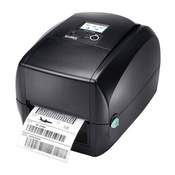
Barcode Printer Getting to Know Your Printer Device Overview Front View PRINTER COVER LCD SCREEN OPERATION PANEL FEED BUTTON DIRECTION KEY POWER BUTTON FRONT COVER COVER RELEASE CATCHES Pull catches for opening the printer cover Rear View FAN-FOLD LABEL INSERT Feed slot for continuous labels USB HOST ETHERNET PORT... - Page 7 Barcode Printer Bottom View COVER OF THE MODULE CONNECTION JACKS **** Cut-outs are not intended for wall-mount use.
- Page 8 Barcode Printer The Internal View of Printer LABEL GUIDE PLATE Set of 2 LABEL SUPPLY HUB Set of 2 LABEL SUPPLY MODULE LABEL GUIDE Set of 2 RELEASE CATCH Release catch for opening the label supply hub RELEASE CATCH Release catch for closing the printer cover LABEL SENSOR MODULE...
- Page 9 Barcode Printer The Printing Mechanism RIBBON REWIND MECHANISM COVER The cover for Ribbon rewind mechanism NOTCH OF RIBBON REWIND WHEEL RIBBON REWIND WHEEL RIBBON SUPPLY PRINT HEAD MECHANISM PAPER PRESS BAR NOTCH OF RIBBON SUPPLY WHEEL RIBBON SUPPLY WHEEL...
-
Page 10: Printer Setup
Printer Setup Open the Printer Open the Printer Cover and the Printing Mechanism Place the printer on a flat surface. Open the printer cover by pulling the cover release catches on both sides of the printer and lift the printer cover. Pull the catches toward the direction Pull the catches toward the direction COVER RELEASE CATCHES... -
Page 11: Loading The Ribbon 007
Printer Setup Loading the Ribbon A New Ribbon Module Installation A NEW RIBBON EMPTY RIBBON CORE RIBBON HUB Attach the ribbon to the empty ribbon core with the adhesive strip at the end of the ribbon. Stick on empty ribbon core Insert the ribbon hub into empty ribbon core and new ribbon. - Page 12 Printer Setup Load the Ribbon on the Printer For Ribbon Supply Module RIBBON SUPPLY MECHANISM NOTCH OF RIBBON SUPPLY WHEEL RIBBON SUPPLY WHEEL Place the ribbon supply module into the printing mechanism. Please the left-hand side of ribbon hub first. Make sure the holder of ribbon hub is inserted into the notch.
- Page 13 Printer Setup Unlock the release catch to close the printer cover. Push the release catch forward to unlock it. The ribbon supply module loading is completed. Close the printer cover Push RELEASE CATCH Release catch for closing the printer cover Load the Ribbon on the Printer For Ribbon Rewind Module RIBBON REWIND MECHANISM...
- Page 14 Printer Setup Open the cover of ribbon rewind mechanism. Open the cover Place the ribbon rewind module into the ribbon rewind mechanism. Please the left-hand side of ribbon hub first. Make sure the holder of ribbon hub is inserted into the notch. Then place the right-hand side of ribbon hub.
- Page 15 Printer Setup Turn the ribbon rewind wheel to tighten the ribbon until it has no wrinkles. Rotate backward RIBBON REWIND WHEEL Close the cover of ribbon rewind mechanism. The ribbon loading is completed once the ribbon supply module and ribbon rewind module are assembled correctly.
-
Page 16: Loading The Label Roll Module 012
Printer Setup Loading the Label Roll Module Loading the Label Stock on the Printer LABEL GUIDE PLATE Set of 2 LABEL SUPPLY HUB Set of 2 LABEL SUPPLY MODULE LABEL STOCK LABEL GUIDE Set of 2 RELEASE CATCH Release catch for opening the label supply hub Unlock the ribbon catch and pull to open the label guide plate. - Page 17 Printer Setup Feed the Label through the label guides. The label guides will help to prevent the label swaying. Through the label guides LABEL GUIDE Set of 2 Unlock the release catch to close the printer cover. Close the printer cover RELEASE CATCH Release catch for closing the printer cover...
-
Page 18: Connecting The Printer To The Host Computer 014
Connect the power cord to the AC adapter. POWER CORD AC ADAPTER Connect the jack of the power adapter to the printer and connect the plug of the power adapter to the socket of the wall. RT700i/RT730i BARCODE PRINTER POWER ADAPTER JACK SLOT THE WALL... - Page 19 Printer Setup Connect the USB/serial cable to the printer and host computer. RT700i/RT730i BARCODE PRINTER USB PORT USB CABLE PLUG PLUG SOCKET Pressing the power button. The power LED indicator should now lights up. Pressing the power button POWER LED INDICATOR...
-
Page 20: Wizard Cd
Printer Setup Installing Printer Driver and GoLabel with Super Wizard CD Insert the Super Wizard CD in the CD/DVD drive of the host computer and the program should pop up automatically. You will see the Welcome screen first. On the Welcome screen, choose “Standard Installation”. The wizard will then ask you to make sure your USB and power cables are connected and that the power is turned on. -
Page 21: Wizard Cd
Printer Setup As the printer driver and GoLabel are installing, a screen will display a progress bar. Once the installation is complete, you can start to make and print labels with GoLabel or throug the printer driver. As the optional steps, you can also print a test label or register your printer during the “Standard Installation” procedure. - Page 22 Insert the product CD in the CD/DVD drive of the host computer and open the "Seagull Drivers" folder on the CD. Select the icon for the driver file and click it to start the installation. Follow the instructions on the screen. The Driver Wizard guides you through the installation procedure. Select "Install printer drivers". Specify your printer model. Godex RT700i...
- Page 23 Printer Setup Specify the port used to connect the printer to the host computer. Enter a printer name and assign the appropriate rights. Godex RT700i Godex RT700i Once the installation is complete, a summary of the printer settings is displayed.
- Page 24 Printer Setup Once the driver installation is complete, the new printer should appear in the "Printers and Faxes" folder. Godex RT700i Godex RT700i...
-
Page 25: Printer Setting And Control
Printer Setting and Control Operation Panel Operation Panel Introduction OPERATION PANEL LCD SCREEN RT700i FEED BUTTON POWER BUTTON DIRECTION KEY POWER Button Press the POWER button to turn on the printer, and the START UP SCREEN appears. The printer is on “ready to print”... -
Page 26: Lcd Interface Introduction 022
Setting and Control for Operation Panel LCD Interface Introduction Getting Started Press the POWER button to turn on the printer, and the START UP SCREEN appears. Power on If the printer is on “ready to print” status, the LCD screen should display the message “Ready“ on the screen. Please keep pressing ... - Page 27 Setting and Control for Operation Panel Operations on Setting Page On MAIN PAGE, press or button to move the cursor and select the functions. Select a designated function and press FEED button, you will enter the SETTING PAGES for the function. Select Enter On SETTING PAGES, press ...
- Page 28 Setting and Control for Operation Panel On SETTING VALUE PAGES, press or button to change the setting values. Select Press FEED button will apply the setting value you just selected, and the red tick will appear to mark the value. Apply **** The blue arrow indicates the value you are selected.
- Page 29 Setting and Control for Operation Panel Exit from Current Page to Ready Status The icon on top-left corner displays the capture of upper level screen and also guides you back to upper level with left or up arrow. NAVIGATION ICON On SETTING VALUE PAGES, press button will go back to the upper level screen.
- Page 30 Setting and Control for Operation Panel On MAIN PAGE, select the “EXIT” icon and press the FEED button to exit from SETTING MODE and the printer goes back to READY status. EXIT from Setting Mode Back to the Ready status...
-
Page 31: Lcd Interface Function 027
Setting and Control for Operation Panel LCD Interface Function Main Page Setting items for printer, ex. Printing speed, darkness. Also includes a Printing Wizard for your ease of printing. Printer Setting Setting items for printing label, ex. Rotation, Printing position offset. Label Setting Option modules and connection port settings. - Page 32 Setting and Control for Operation Panel Setting Items in Setting Mode English German LCD Language 繁體中文 简体中文 Printer Setting Speed 2-5 or 7 Darkness 0-19 Label with Gaps Media Type Label with Marks Wizard Continuous Direct Thermal Printer Mode Thermat Transfer Tear-off Position 0-40 Darkness...
- Page 33 Setting and Control for Operation Panel Apply Buzzer Cancel None Cutter Option Device Label Dispensor Optional Setting Applicator Apply Pre-Printing Cancel 4800 bps 9600 bps 19200 bps Baud Rate 38400 bps 57600 bps 115200 bps Serial Port Setting Parity Even 7 bits Data bits 8 bits...
- Page 34 Setting and Control for Operation Panel Status of LCD Interface When printer is on standby status (ready to print), the LCD interface will display “Ready” on screen. You can only print on this “Ready“ status. If there is any printers error, the LCD screen will display the error screen to show the type of error. You can fix the error according the notice.
-
Page 35: Label Calibration And Self Test 031
The printer will now measure the label stock and store the label height. Once the printer has successfully measured the label stock, it will print a self-test label. The contents of a self-test printout are listed below. RT700i:GX.XXX Model & Version USB S/N:12345678... - Page 36 Printer Setting and Control Label Calibration Button A hardware button to make a Label Calibration while printer encountering ‘’Media Error’’ during the cases when first-time printer start up or change label or ribbon to another type, such as change using gap label to continuous or black mark labels.
-
Page 37: Error Alerts 033
Setting and Control for Operation Panel Error Alerts In the event of a problem that prevents normal functioning of the printer, you will see an error message on LCD screen and hear some beep signals. Please refer to below table for the error alerts. OPERATION PANEL LCD SCREEN FEED BUTTON... - Page 38 Setting and Control for Operation Panel Operation Panel Status Type Beeps Description Solution The memory is full. The printer Delete unnecessary data or install prints the message "File System full additional memory. ". Use the "~X4" command to print Unable to find file. The printer all files.
-
Page 39: Usb Host 035
USB memory stick : It supports hot-plugging function; printer will create a Folder ‘’\LABELDIR’’ and switch ‘’User Flash’’ to ‘’ Extended Memory‘’ automatically while user plugs an USB memory stick into a GoDEX ‘’i’’ model printer. Connect the USB Stick plugged -in printer to PC via USB Device or Ethernet port and run ‘’GoLabel’’ software to ... - Page 40 Printer Setting and Control USB Keyboard When plug-in an USB keyboard to the printer, LCD panel will display “Standalone Mode”, press the “Enter” key on keyboard and “Feed” key in the printer to entering to the dialog for “Recall Label” operation. Only the sub-dialog “Recall Label”...
-
Page 41: Netsetting For Ethernet
NetSetting for Ethernet Installing the NetSetting software The NetSetting software is used to manage the network configurations when connecting the printer via Ethernet port. It is available on product CD or can be downloaded from official website. To install the NetSetting, please follow below steps. -
Page 42: The Interface Of Netsetting 038
PC. RT700i Click the magnifier icon to search the Godex printers which are connected via Ethernet port in you network environment. Once a connected Godex printer is detected, it will be listed on the start page. - Page 43 NetSetting for Ethernet IP Setting The IP Setting tab can change the printer name, Port number, Gateway setting and the password for configuring the printer. You can also set the printer’s IP address ether by DHCP or by Static IP. You can press “Set”...
- Page 44 NetSetting for Ethernet Alert Path Setting NetSetting will send the alert messages to designated mail account when the error happened on printer. The alert messages are sent by SMTP (Simple Mail Transfer Protocol) or SNMP (Simple Network Management Protocol). You can set or change the configurations of SMTP and SNMP on this “Alert Path Setting” tab. You can press “Set”...
- Page 45 NetSetting for Ethernet Alert Message Setting For the alert message notification function, you can decide which error cases need to be sent out to the operator. Moreover, the alert messages can be set to be sent by SMTP, SNMP or both. You can press “Set”...
- Page 46 Set or change the configurations of connected printer. Most of key settings for the printer operation can be done by this setting page. RT700i You can press “Set” button to apply the settings and “ReGet” button to refresh the setting values.
- Page 47 NetSetting for Ethernet User Command The “User Command” tab provides a communication interface for operator to control the printer. Input printer commands in "Input Command" window and press “Send Command” button, the commands will be sent to the printer. For some commands that will return response message, the message will be displayed in "Output Message" window. You can press “Send Command”...
- Page 48 “Start Download Firmware” button. The printer firmware then can be updated remotely. BOOT : 1.000a1 F/W : RT700i 1.000a In addition to the firmware update, you can press “Recover To Factory Settings” button to restore the printer...
-
Page 49: Accessories 045
Accessories Preparation Steps Before installing the optional modules, please make some preparations as follows. Turn off the printer : Remember to switch off the printer before installing any module. Open the printer cover and the printing mechanism : Open the printer cover by pulling the release catches on both sides of the printer and lift the cover. Please see the Section 2.1 for further information about Open the Printer. - Page 50 Accessories Remove the platen : Lift up the release clips on both sides of the platen to release and pull upward the platen. Release the clip CLIP PLATEN MODULE Pull up the platen module Ribbon loading : Please see the Section 2.2 for further information about Loading the Ribbon. Label loading Please see the Section 2.3 for further information about Loading the Label Roll Module.
-
Page 51: Installing The Label Dispenser 047
Accessories Installing the Label Dispenser The Overview of the Label Dispenser PAPER SENSOR PAPER FEED ROLLER CONNECTION CABLE OF LABEL DISPENSER COVER Preparation Steps Please see the Section 5.1 Preparation Steps to complete the preparation steps before installing the label dispenser. Installing the Label Dispenser Pass the connection cable through the slot of the printer. - Page 52 Accessories Place label dispenser to align both holes of screw and then tighten the screws. Tighten the screw Open the cover Place the platen back to the printer and lock the clips. Lock the clip CLIP Close the printer cover and printing mechanism. Then to turn the printer upside down.
- Page 53 Accessories Open the cover on the bottom of printer. COVER OF THE MODULE CONNECTION JACKS Open the cover Plug the connector fo the label dispenser to the jack. Plug JACK CONNECTOR OF THE CONNECTION CABLE Close the cover of the module connection jacks. COVER OF THE MODULE CONNECTION JACKS Close the cover ****The printer must be switched off when plugging the connector, or the motherboard may be destroyed!
- Page 54 Accessories Loading Label Roll with the Label Dispenser Module Remove the first label from the label stock. LABEL STOCK LABEL LINER Tear a label THE FIRST LABEL Feed the Label stock through the label guides. And pull the label liner through the platen and the steel of the label dispenser. Through the label guides Through the platen and the steel...
- Page 55 Accessories The feeding path of label and liner should be as shown in below graphic. LABEL LABEL LINER PLATEN LABEL STOCK ROLLER Close the label dispenser and printer cover. The installation is completed now. Close the cover...
- Page 56 Accessories Press the FEED button to feed the label. The label will be peeled from the liner while it passes through the label dispenser. Press the feed key LABEL LABEL LINER **** There is a paper sensor on the Label Dispenser module. It will stop the printing if it is covered by label. Remove the last printed label and the printer will then continue to print next label.
-
Page 57: Installing The Cutter 053
Accessories Installing the Cutter The Overview of the Cutter CONNECTION CABLE OF CUTTER FEED-OUT SLOT COVER Preparation Steps Please see the Section 5.1 Preparation Steps to complete the preparation steps before installing the cutter. Installing the Cutter Pass the connection cable through the slot of the printer. SLOT ****Remember to switch off the printer before installing the cutter. - Page 58 Accessories Place the cutter to align both holes of screw and then tighten the screws. Tighten the screw Place the platen back to the printer and lock the clips. Lock the clip CLIP Close the printer cover and printing mechanism. Then to turn the printer upside down.
- Page 59 Accessories Open the cover on the bottom of printer. COVER OF THE MODULE CONNECTION JACKS Open the cover Plug the connector for the cutter to the jack. Plug JACK CONNECTOR OF THE CONNECTION CABLE Close the cover of the module connection jacks. COVER OF THE MODULE CONNECTION JACKS Close the cover ****The printer must be switched off, or the motherboard may be destroyed!
- Page 60 Accessories Installing the Label Roll Module on the Printer Pass the labels through the guides and the cutter. Through the label guides Through the cutter Close the top cover and printing mechanism. To finish, press the FEED button to set the label position. Close the top cover Push Press the feed key...
-
Page 61: Maintenance And Adjustment 057
Maintenance and Adjustment Cleaning the Print Head Dirt on the print head or ribbon, or glue residue from the label stock may result in inadequate print quality. The printer cover must therefore always be closed during printing. Keeping dirt and dust away from the paper or labels ensures a good print quality and a longer lifespan of the print head. -
Page 62: Troubleshooting 058
Maintenance and Adjustment Troubleshooting Problem Solution Check the power supply. ♦ The printer is switched on but the LED does not light up. Please see the Section 2.4 ♦ Check the software settings (driver settings) or command codes. ♦ Look for the error alert in the table in Section 3.5. Error Alerts. The LED lights up red and printing is interrupted. -
Page 63: Appendix
RT700i/RT730i USER MANUAL APPENDIX PRODUCT SPENIFICATIONS RT700i RT730i Model Print Method Thermal Transfer / Direct Thermal Resolution 203 dpi (8 dots/mm) 300 dpi (12 dots/mm) Print Speed Up to 7 IPS (177 mm/s) 5 IPS (127 mm/s) Print Width 4.25” (108 mm) 4.16”... - Page 64 ** Minimum print height and maximum print speed specification compliance can be dependent on non-standard material variables such as label type, thickness, spacing, liner construction, etc. Godex is pleased to test non-standard materials for minimum print height and maximum print speed capability.
-
Page 65: Interface
RT700i/RT730i USER MANUAL APPENDIX INTERFACE Pinout Description Connector Type : Type B Pin NO. Function VBUS Serial Port Default settings: Baud rate 9600, no parity, 8 data bits, 1 stop bit, XON/XOFF protocol and RTS/CTS RS232 Housing(9-pin to 9-pin) -
Page 66: File Manipulation When Using Usb Stick
RT700i/RT730i USER MANUAL APPENDIX FILE MANIPULATION WHEN USING USB STICK File Manipulation The files in both devices (USB memory stick and printer internal Flash memory) are able to copy and move by the commands ‘’~MCPY’’ and ‘’MMOV’’ that sends from GoLabel on a PC via either connection - USB or Ethernet ports.
Need help?
Do you have a question about the RT700i and is the answer not in the manual?
Questions and answers