
Related Manuals for Godex RT800i Series


Summary of Contents for Godex RT800i Series
- Page 1 RT800i SERIES BARCODE PRINTER USER MANUAL User Manual: RT800i Series Version : Ver. E.6 Issue Date : 2022/09/01 : 920-015411-00...
-
Page 2: Table Of Contents
Contents 1 Barcode Printer ..............................................5 1.1 Box Content ............................................5 1.2 Barcode Printer ............................................. 6 2 Printer Setup ................................................10 2.1 Open the Printer ..........................................10 2.2 Loading the Ribbon..........................................11 2.3 Loading the Label Roll Module .......................................16 2.4 Connecting the Printer to the Host Computer ................................18 2.5 Wizard CD Standard Installation .....................................20 2.6 Wizard CD Other Choice Installation.....................................23 3 Printer Setting and Control ...........................................26... - Page 3 FCC COMPLIANCE STATEMENT FOR AMERICAN USERS This equipment has been tested and found to comply with the limits for a CLASS A digital device, pursuant to Part 15 Subpart B of the FCC Rules. These limits are designed to provide reasonable protection against harmful interference when the equipment is operated in a commercial environment.
- Page 4 SAFETY INSTRUCTIONS Please read the following instructions carefully. Keep the equipment away from humidity. Before you connect the equipment to the power outlet, please check the voltage of the power source. Make sure the printer is off before plugging the power connector into the power jack. It is recommended that you connect the printer to a surge protector to prevent possible transient overvoltage damage.
-
Page 5: Barcode Printer
Barcode Printer 1.1 Box Content Please check that all of the following items are included with your printer. Package content and Logo style may vary per region. •RT800i Barcode Printer •Label Stock •USB Cable •Quick Guide •Ribbon Module •Power Adapter Empty Ribbon Core Power Cord AC Adapter... -
Page 6: Barcode Printer
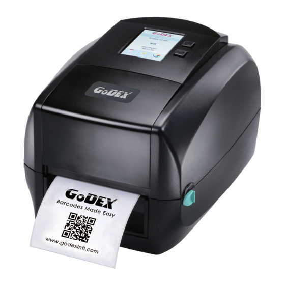
1.2 Barcode Printer Device Overview • Front View PRINTER COVER POWER BUTTON FEED BUTTON TOUCH PANEL FRONT COVER COVER RELEASE CATCHES Pull catches for opening the printer cover • Rear View FAN-FOLD LABEL INSERT Feed slot for outside continuous labels PARALLEL PORT USB HOST CALIBRATION BUTTON... - Page 7 • Bottom View COVER OF THE MODULE CONNECTION JACKS Note Cut-outs are not intended for wall-mount use. Please make sure that the machine and personnel protective measures in case you need to use the wall-mount.
- Page 8 • The Internal View of Printer LABEL GUIDE PLATE Set of 2 LABEL SUPPLY HUB Set of 2 LABEL SUPPLY MODULE LABEL GUIDE Set of 2 RELEASE CATCH Release catch for opening the label supply hub RELEASE CATCH Release catch for closing the printer cover LABEL SENSOR MODULE...
- Page 9 The Printing Mechanism RIBBON REWIND MECHANISM COVER The cover for Ribbon rewind mechanism NOTCH OF RIBBON REWIND WHEEL RIBBON REWIND WHEEL RIBBON SUPPLY MECHANISM PRINT HEAD PAPER PRESS BAR NOTCH OF RIBBON SUPPLY WHEEL RIBBON SUPPLY WHEEL...
-
Page 10: Printer Setup
Printer Setup 2.1 Open the Printer Open the Printer Cover and the Printing Mechanism Place the printer on a flat surface. Open the printer cover by pulling the cover release catches on both sides of the printer and lift the printer cover. Pull the catches toward the direction Pull the catches toward... -
Page 11: Loading The Ribbon
2.2 Loading the Ribbon A New Ribbon Module Installation A NEW RIBBON EMPTY RIBBON CORE RIBBON HUB 1. Attach the ribbon to the empty ribbon core with the adhesive strip at the end of the ribbon. Stick on empty ribbon core 2. - Page 12 Load the Ribbon on the Printer For Ribbon Supply Module RIBBON SUPPLY MECHANISM NOTCH OF RIBBON SUPPLY WHEEL RIBBON SUPPLY WHEEL 1. Place the ribbon supply module into the printing mechanism. Please the left-hand side of ribbon hub first. Make sure the holder of ribbon hub is inserted into the notch. Then place the right-hand side of ribbon hub. Left side RIBBON SUPPLY Place...
- Page 13 Unlock the release catch to close the printer cover. Push the release catch forward to unlock it. The ribbon supply module loading is completed. Push Close the printer cover RELEASE CATCH Release catch for closing the printer cover Load the Ribbon on the Printer For Ribbon Rewind Module RIBBON REWIND MECHANISM COVER...
- Page 14 1. Open the cover of ribbon rewind mechanism. Open the cover 1. Place the ribbon rewind module into the ribbon rewind mechanism. Please the left-hand side of ribbon hub first. Make sure the holder of ribbon hub is inserted into the notch. Then place the right-hand side of ribbon hub.
- Page 15 3. Turn the ribbon rewind wheel to tighten the ribbon until it has no wrinkles. Rotate backward RIBBON REWIND WHEEL 4. Close the cover of ribbon rewind mechanism. The ribbon loading is completed once the ribbon supply module and ribbon rewind module are assembled correctly.
-
Page 16: Loading The Label Roll Module
2.3 Loading the Label Roll Module Loading the Label Stock on the Printer LABEL GUIDE PLATE Set of 2 LABEL SUPPLY HUB Set of 2 LABEL LABEL STOCK SUPPLY MODULE LABEL GUIDE Set of 2 RELEASE CATCH Release catch for opening the label supply hub 1. - Page 17 3. Feed the Label through the label guides. The label guides will help to prevent the label swaying. Through the label guides LABEL GUIDE Set of 2 4. Unlock the release catch to close the printer cover. Close the printer cover RELEASE CATCH Release catch for closing the printer cover...
-
Page 18: Connecting The Printer To The Host Computer
2.4 Connecting the Printer to the Host Computer 1. Please make sure that the printer is switched off. 2. Connect the power cord to the AC adapter. POWER CORD AC ADAPTER Connect the jack of the power adapter to the printer and connect the plug of the power adapter to the socket of the wall. - Page 19 3. Connect the USB/serial cable to the printer and host computer. RT860i BARCODE PRINTER USB CABLE USB PORT PLUG PLUG SOCKET 4. Pressing the power button. The Touch Panel LCD will lights up. Pressing the power button TOUCH PANEL LCD...
-
Page 20: Wizard Cd Standard Installation
2.5 Wizard CD Standard Installation 1. Insert the Super Wizard CD in the CD/DVD drive of the host computer and the installation program should pop up automatically. You will see the Welcome screen first. On the Welcome screen, choose “STANDARD INSTALLATION”. 2. - Page 21 4. As the printer driver and GoLabel are installing, a screen will display a progress bar. While downloading completed you will see Installation completed. Click “NEXT” to continue. 5. You can also print a test label. If don’t print a test label, the screen display as step 6. Note * If you need more resources, tools or reference documents, you can also find them on Super Wizard CD.
- Page 22 6. Once the installation is complete, you can start to make and print labels with GoLabel or through the printer driver.
-
Page 23: Wizard Cd Other Choice Installation
2.6 Wizard CD Other Choice Installation 1. Click “OTHER CHOICES” to next screen and select “PRINTER DRIVERS”. 2. Click “INSTALL SEAGULL SCIENTIFIC WINDOWS DRIVER” to next screen, and click “NEXT”. 3. Select “I accept the terms in the license agreement”, and click ”Next”,then click ”Finish” to step 4. - Page 24 4. The Driver Wizard will guide you through the installation procedure. Select "Install printer drivers" and click “Next”. 5. With a USB connection, search models such as the right diagram printer device. Specify your printer model and click ”Next”. 6. Enter the printer name (you can use default), then click "Next" to display as right diagram. Click "Finish"...
- Page 25 7. Driver installation completed.
-
Page 26: Printer Setting And Control
Printer Setting and Control 3.1 Operation Panel OPERATION TOUCH PANEL POWER BUTTON FEED BUTTON TOUCH PANEL POWER Button Press the POWER button to turn on the printer, and the START UP SCREEN appears. The printer is on “ready to print” status, the LCD screen should display the message “READY“ on the screen. When printer is turned on, hold and press down the POWER button for 3 second will turn the printer off. -
Page 27: Lcd Interface Introduction
3.2 LCD Interface Introduction Getting Started Press the POWER button to turn on the printer, and the START UP SCREEN appears. Power on If the printer is on “ready to print” status, the LCD screen should display the message “Ready“ on the screen. Use touch gestures to get around the main screen and other screen for setting. - Page 28 On the Ready Page, three function mode for setting. You can make various setting functions in FUNCTIONAL MODE. 主選單 Main RT8XXi VX.XXX Tap‘’Main ‘’-- Printer Code Settings Langua Ready Page Screen could show more detail of‘’ Label Main‘’ Printer Devices Settings Control Recall...
- Page 29 Printer Settings Main Darkness finish setting tap Printer Speed back to Main page, if Langua Settings Sensor Auto Select do not save, tap Select Label Printer Devices Settings Control system back to Main page Media Continuous Type and would not save any Recall changes.
- Page 30 Keyboard Mode When plug-in an USB keyboard to the printer, LCD touch panel will display “Enter Standalone”, press the “Y” key on keyboard to entering to the dialog for “Keyboard Mode” operation. Recall Country Enter Standalone Label Code (Y/N) Database Label Clock Setting...
- Page 31 From the Recall Label Page Recall Label Recall Label the touch panel shown on all labels, Tap up to choose labels. Tap down to choose labels. Preview Label Tap Preview Label can see printing label. 預覽標籤 Preview Preview Label Label Keeping tap to next page Print out selected label.
-
Page 32: Lcd Interface Function
3.3 LCD Interface Function Main Page Main Printer Settings Languag Label Printer Devices Settings Control Recall Label Setting items for printer, ex. Printing speed, darkness. Also includes a Printing Wizard for your ease of printing. 10 languages for printer setting It consists of a table of values that describes the character set for a particular language Setting items for printing label, ex. - Page 33 Device Page Main Devic Printer Option Programing Buzzer Settings Languag Setting Language Label Serial Port Printer Devices Settings Setting Control Setting Setting Recall Bluetooth Clock WiFi Label Setting Setting Setting Setting off or on for buzzer Setting items for options, ex. Cutter, Label Dispenser, Applicator Setting Programing Language.
- Page 34 Setting Items in LCD Setting Mode Darkness 0-19 Speed Auto Select Sensor Select See-Through Reflective Label with Gaps Media Type Label with Marks Printer Settings Continuous Direct Thermal Printing Mode Thermal Transfer Tear-off Position 0-40 Top of Form FULL Door Open Only English Deutsch Franç...
- Page 35 115200 None Parity Even Data Bits Stop Bits DHCP OFF/ ON IP Address 0.0.0.0 LAN Setting Subnet Mask 255.255.255.0 Gateway 192.168.0.254 Password OFF / ON LCD Setting Correction Visible OFF / ON Clock Setting Y/M/D/H/Min. Configuration Directory Test TPH Testing Dump Mode Sample Pattern Self-test page / Balance...
- Page 36 Status of LCD Interface When printer is on standby status (ready to print), the LCD interface will display “Ready” on screen. You can only print when you see the “Ready“ status. Ready Main Wizard Test If there is any printers error, the LCD screen will display the error screen to show the type of error. You can fix the error according the notice or contact the supplier.
-
Page 37: Label Calibration And Self Test
3.4 Label Calibration and Self Test Label Calibration The printer can automatically detect and store label height. That means the host computer does not need to transmit the label height to the printer. Self Test Self-test function lets you check whether the printer is functioning normally. Here is how you run the label size calibration and self test. - Page 38 Label Calibration Button A hardware button to make a Label Calibration while printer encountering “Media Error” during the cases when first-time printer start up or change label to another type, such as change using gap label to continuous black mark labels. CALIBRATION BUTTON Press and hold about 1 ~ 2 seconds...
-
Page 39: Error Alerts
3.5 Error Alerts In the event of a problem that prevents normal functioning of the printer, you will see an error message on LCD screen and hear some beep signals. Please refer to below table for the error alerts. Operation Panel Type Beeps Description... - Page 40 The memory is full. Delete unnecessary The printer prints data or install the message "File additional memory. System full ". Use the "~X4" File System Full Unable to find file. command to print all The printer prints files. Then check the message "File whether the files exist not found"...
-
Page 41: Usb Host
USB memory stick : It supports hot-plugging function; printer will create a Folder ‘’\LABELDIR’’ and switch User Flash” to ‘’ Extended Memory‘’ automatically while user plugs an USB memory stick into a GoDEX printer. Connect USB with the printer; To connect PC and printer through USB. - Page 42 USB Keyboard = When plug-in an USB keyboard to the printer, LCD touch panel will display “Enter Standalone”, press the “Y” key on keyboard to entering “Keyboard Mode” operation. Under this model can perform "Recall Label", set "Country Code", "Code Page", "Clock Setting", "Database Setting" and "Label Edit". = Connect a USB keyboard to the printer, if not into the keyboard mode, press the "N"...
-
Page 43: Dump Mode Begin
3.7 Dump Mode Begin For make sure provide us correct information for check what commands sentfrom the PC or software, please following below steps, STEP 1, Let the printer enter Dump Mode Here is how you switch to dump mode: On the Ready Page, three function mode for setting. -
Page 44: Netsetting For Ethernet
NetSetting for Ethernet 4.1 Installing the NetSetting software The NetSetting software is used to manage the network configurations when connecting the printer via Ethernet port. It is available on product CD or can be downloaded from official website. To install the NetSetting, please follow below steps. - Page 45 5. Once the installation is completed, you will see the NetSetting icon on your desktop as right diagram.
-
Page 46: The Interface Of Netsetting
4.2 The Interface of NetSetting GoDEX printer can also be used through a network connection (as a remote network printer), make sure the printer connected to the Internet and the power cord, you can use the Interface of NetSetting to search connected network printers. - Page 47 IP Setting The IP Setting tab can change the printer name, Port number, Gateway setting and the password for configuring the printer. You can also set the printer’s IP address ether by DHCP or by Static IP. You can press “Set” button to apply the settings and “ReGet” button to refresh the setting values.
- Page 48 Alert Path Setting NetSetting will send the alert messages to designated mail account when the error happened on printer. The alertmessages are sent by SMTP (Simple Mail Transfer Protocol) or SNMP (Simple Network Management Protocol). You can set or change the configurations of SMTP and SNMP on this “Alert Path Setting” tab. You can press “Set”...
- Page 49 Alert Message Setting For the alert message notification function, you can decide which error cases need to be sent out to the operator. Moreover, the alert messages can be set to be sent by SMTP, SNMP or both. You can press “Set” button to apply the settings and “ReGet” button to refresh the setting values.
- Page 50 Printer Configuration Set or change the configurations of connected printer. Most of key settings for the printer operation can be done by this setting page. You can press “Set” button to apply the settings and “ReGet” button to refresh the setting values.
- Page 51 User Command The “User Command” tab provides a communication interface for operator to control the printer. Input printer commands in "Input Command" window and press “Send Command” button, the commands will be sent to the printer. For some commands that will return response message, the message will be displayed in "Output Message" window.
- Page 52 Firmware Download On “Firmware Download” tab, the current version of printer firmware will be showed on the screen. If you need to update the printer firmware, just specify the file location of firmware file and press “Start Download Firmware” button. The printer firmware then can be updated remotely. In addition to the firmware update, you can press “Recover To Factory Settings”...
-
Page 53: Accessories
Accessories 5.1 Preparation Steps Before installing the optional modules, please make some preparations as follows. 1. Turn off the printer : Remember to switch off the printer before installing any module. 2. Open the printer cover and the printing mechanism : Open the printer cover by pulling the release catches on both sides of the printer and lift the cover. - Page 54 4. Remove the platen : Lift up the release clips on both sides of the platen to release and pull upward the platen. Release the clip CLIP PLATEN MODULE Pull up the platen module 5. Ribbon loading Please see the Section 2.2 for further information about Loading the Ribbon. 6.
-
Page 55: Installing The Label Dispenser
5.2 Installing the Label Dispenser The Overview of the Label Dispenser PAPER SENSOR PAPER FEED ROLLER CONNECTION CABLE OF LABEL DISPENSER COVER Preparation Steps Please see the Section 5.1 Preparation Steps to complete the preparation steps before installing the label Dispenser. - Page 56 3. Place label dispenser to align both holes of screw. 4. Open the cover of the label dispenser, and then tighten the screws. Open the cover Tighten the screws Screw Hole 5. Close the printer cover and printing mechanism. Then to turn the printer upside down. Close the printer cover Push Push...
- Page 57 6. Open the cover on the bottom of printer. COVER OF THE MODULE CONNECTION JACKS Open the cover 7. Plug the connector fo the label dispenser to the jack. Plug JACK CONNECTOR OF THE CONNECTION CABLE 8. Close the cover of the module connection jacks. COVER OF THE MODULE CONNECTION JACKS Close the cover Note...
- Page 58 Loading Label Roll with the C Module 1. Remove the first label from the label stock. LABEL STOCK LABEL LINER Tear a label THE FIRST LABEL 2. Feed the Label stock through the label guides. And pull the label liner through the platen and the steel of the label dispenser. Through the label guides Through the platen and the steel...
- Page 59 3. The feeding path of label and liner should be as shown in below graphic. LABEL LABEL LINER PLATEN LABEL STOCK ROLLER 4. Close the label dispenser and printer cover. The installation is completed now. Close the cover...
- Page 60 5. Press the FEED button to feed the label. The label will be peeled from the liner while it passes through the label dispenser. Press the feed key LABEL LABEL LINER Note * There is a paper sensor on the Label Dispenser module. It will stop the printing if it is covered by label. Remove the last printed label and the printer will then continue to print next label.
-
Page 61: Installing The Cutter
5.3 Installing the Cutter The Overview of the Cutter CONNECTION CABLE OF CUTTER FEED-OUT SLOT COVER Preparation Steps Please see the Section 5.1 Preparation Steps to complete the preparation steps before installing the cutter. Installing the Cutter 1. Pass the connection cable through the slot of the printer. SLOT Note * Remember to switch off the printer before installing the cutter. - Page 62 2. Place the cutter to align both holes of screw and then tighten the screws. (Screw holes on the front side of the bottom barcode Printer) Tighten the screw 3. Place the platen back to the printer and lock the clips. Screw Hole Lock the clip CLIP...
- Page 63 5. Open the cover on the bottom of printer. COVER OF THE MODULE CONNECTION JACKS Open the cover 6. Plug the connector for the cutter to the jack. Plug JACK CONNECTOR OF THE CONNECTION CABLE 7. Close the cover of the module connection jacks. COVER OF THE MODULE CONNECTION JACKS Close the cover Note...
- Page 64 Installing the Label Roll Module on the Printer 1. Pass the labels through the guides and the cutter. Through the label guides Through the cutter 2. Close the top cover and printing mechanism. To finish, press the FEED button to set the label position. Close the top cover Push Press the feed...
-
Page 65: Cleaning Method
5.4 Cleaning Method 1.Remove the screws and cover. 2.Wipe with a cotton swab or dry lint-free cloth... -
Page 66: Installing The (For Rt860I)
5.5 Installing the (For RT860i) Step 1. Power off and open the option cover. Step 2. Push the module till the indication line aligns to the edge of mainboard to avoid signal error. Insert Bluetooth module into the slot. Step 3. Close the option cover. -
Page 67: Installing The Bluetooth Module (For Rt833I、Rt863I)
5.5 Installing the bluetooth module (For RT833i、RT863i) Step 1. Step 2. *Bluetooth Module Step 3. -
Page 68: Installing The Wifi Module (For Rt860I)
Incorrect installations below must be avoid. Power off before installing the WiFi module. * Due to RT800i Series WiFi module message communication through LAN port, please make sure WiFi module has been removed when you want to use LAN port. -
Page 69: Installing The Wifi Module (For Rt833I/Rt863I)
5.6 Installing the WiFi Module (For RT833i/RT863i) Step 1. Step 3. Step 2. -
Page 70: Maintenance And Adjustment
Maintenance and Adjustment 6.1 Cleaning the Print Head Dirt on the print head or ribbon may result in inadequate print quality (there are only partial images on the label). The printer cover should therefore be kept closed when possible. Keeping dirt and dust away from the paper or labels ensures a good print quality and a longer lifespan of the print head. -
Page 71: Troubleshooting
6.2 Troubleshooting Problem Solution The printer is switched on but the LED does not light ◆ Check the power supply. Please see the Section 2.4 ◆ Check the software settings (driver settings) or command codes. ◆ Look for the error alert in the table in Section 3.3 Error Alerts. The LED lights up red and printing is interrupted. -
Page 72: Appendix─Product Spenifications
APPENDIX─PRODUCT SPENIFICATIONS Model RT833i Print Method Thermal Transfer / Direct Thermal Resolution 300 dpi (12 dots/mm) Print Speed 5 IPS (127 mm/s) Print Width 105.7 mm (4.16”) Min. 0.16” (4 mm)**; Print Length Max. 30” (762 mm) Processor 32 bit RISC CPU Flash 128 MB Flash (60 MB for user storage) Memory... - Page 73 Model RT860i Print Method Thermal Transfer / Direct Thermal Resolution 600 dpi (23.6 dots/mm) Print Speed 3 IPS (76.2 mm/s) Print Width 4.16” (105.6mm) Min. 0.16” (4 mm)** Print Length Max. 15” (381 mm) Processor ARAM9 CPU Flash 128 MB Flash (60 MB for user storage) Memory SDRAM 32 MB...
- Page 74 Godex is pleased to test non-standard materials for minimum print height and maximum print speed capability. * Due to RT800i Series WiFi module message communication through LAN port, please make sure WiFi module has been removed when you want to use LAN port.
-
Page 75: Appendix─Communication Port Specifications
APPENDIX─Communication Port Specifications Pinout Description USB Host Power USB Port Serial Port Ethernet Port Parallel Port Jack USB Port Connector Type:Type B Pin NO. Serial Port Default Settings : Baud rate 9600, no parity, 8 data bit, 1 stop bit, XON/XOFF Protocal and RTS/CTS RS232 Housing (9-pin to 9-pin) Pin NO. -
Page 76: Appendix─File Manipulation When Using Usb Stick
APPENDIX─FILE MANIPULATION WHEN USING USB STICK File Manipulation The files in both devices (USB memory stick and printer internal Flash memory) are able to copy and move by the commands ‘’~MCPY’’ and ‘’MMOV’’ that sends from GoLabel on a PC via either connection - USB or Ethernet ports. -
Page 77: Appendix─Bluetooth Setting
APPENDIX─Bluetooth setting Steps for setting bluetooth module Step 1. Power off the printer Step 2. Install the Bluetooth module Note : Methods for installing Bluetooth module, please refer to Bluetooth module manual. Step 3. A gray Bluetooth icon will be displayed in the main page after switching on the printer and it indicates that the printer has detected the Bluetooth module. - Page 78 Steps for setting Bluetooth keyboard Active the Bluetooth keyboard to be detectable Step 1. Press “Connect” button. After connecting to a Bluetooth keyboard , the printer will detect Bluetooth keyboard automatically, as the figure indicates below. “Connect“ button Power Step 2. The indicator at the upper left corner of Bluetooth keyboard will flash blue when it has been detected. Step 3.
- Page 79 Steps for setting bluetooth connection on the LCD panel Step 1. Turn on the printer and LCD panel will Step 3. Select“Devices” display ”Main menu” Step 2. Select ”Main” Main Printer Ready Languag Settings Label Printer Devices Settings Control Main Wizard Test Recall...
- Page 80 Step 6 . The LCD panel will display ”Waiting” when the printer detects the Bluetooth keyboard (figure left). When the Bluetooth keyboard is detected by the printer, the monitor will indicate the information of Bluetooth keyboard (figure right). Search Devices MAC Address Waiting Device...
- Page 81 Step 8 . When the connection is successfully created, the current panel will be automatically switched to the setting menu of Bluetooth, as the figure below indicates. (The upper left corner of Bluetooth keyboard will stop flashing at this time.) Bluetooth Settings HID Mode...
- Page 82 Steps for creating the connection between cellphone and printer via bluetooth Set the bluetooth value of the printer Step 1. Power on the printer and LCD panel displays” Main manu” Step 3. Select ”Device” Step 2. Select ”Main” Main Printer Settings Languag Ready...
- Page 83 Set the bluetooth function of the mobile phone (Go App only support Android system and the methods of setting Bluetooth may vary from each mobile phone .) Step 1. Open “Setting manu of mobile phone and select “Bluetooth” . Step 2. After selecting “Open” of Bluetooth, mobile phone will automatically detect Bluetooth devices. Select the desired device name.
- Page 84 Step 3. Activate ”Go APP” Step 4. Select the icon at the bottom right of”Go APP” Step 5. Select the desired device name Step 6. The icon at the bottom right of ”Go APP” and MAC Address will turn blue when the mobile phone and Bluetooth are properly connected.
- Page 85 Steps for creating the connection between PC and printer via bluetooth Set bluetooth parameters of the printer Step 1. Power on the printer and LCD panel Step 3. Select “Devices” displays ”Main manu” Step 2. Select ”Main” Main Printer Code Ready Settings Languag...
- Page 86 Activate”BlueSoleil Space”and creat the connection after inserting the Bluetooth device into the slot of PC Mainframe Step 1. Insert the Bluetooth device Step 2. Activate”BlueSoleil Space” into the slot of PC Mainframe (Each Bluetooth device has its compatible software) Step 3. Select the desired icon with the mouse and right-click on the mouse Step 4.
- Page 87 Step 7. Right-click on the mouse and select ”Connect Bluetooth Serial Port”(see the left figure below), Then,the screen displays a message of essablishing a connection, as the right figure below indicates. Step 8. Input the Bluetooth code :0000 (default) Note : The Bluetooth code does not need to be inputted when the SSP mode of the Bluetooth setting in the printer and the PC is set “Activated”.
- Page 88 Introduction of the Bluetooth parameters Bluetooth Settings SPP Mode Profile Clear Bind Search Devices The Bluetooth code is not needed to be inputted when the SSP mode of the Bluetooth setting in the printer and the PC/Keyboard is set “Activated”. Please select “Clear Bind”, you are allowed to change the setting after the connection is successfully created.
-
Page 89: Appendix─Wi-Fi Setting
APPENDIX─Wi-Fi Setting Steps for setting Wi-Fi module Step 1. Turn Off the Power Step 2. Insert the Wireless Module Please follow the “Wireless Module Installation Manual” to insert the wireless module of RT863i Step 3. The screen will display a grey Wi-Fi icon, and this means the printer has successfully detected the wireless module. - Page 90 Matching the Wireless Access Point Through Touch Panel Step 1. Turn on the printer and LCD panel will Step 3. Select “Devices” display ”Main menu” Step 2. Select ”Main” Main Printer Code Ready Settings Language Page Printer Label Devices Control Settings Wizard Main...
- Page 91 Step 6. Wi-Fi device lists will pop-up Step 7. Choose the assigned Wi-Fi after a few seconds device then press the ON button Search Search Devices Devices Step 8. Click on Password Step 9. Insert Password and Click Column WPA/WPA2 Pre-Share Encryption Auth...
- Page 92 Step 11. When Wi-Fi module is successfully Step 10. Click on again and installed, the printer will restart connect to AP WPA/WPA2 Encryption Auth Pre-Share Step 12. If the Wi-Fi Icon turns purple, it means the printer is connected to a Wi-Fi device Ready Wizard Test...
- Page 93 Definition of Wireless Devices Interface Search Devices Item Explanation Serial Number Number of current connecting devices / Total device number SSID Lists of Wi-Fi options. It shows 5 devices at a time (Highlighted item is the current connecting device) Up/Down Click Up/Down button to switch the connecting devices Password It means the device needs password to connect...
- Page 94 How to connect to a wireless access point through GoLabel Step 1. Open GoLabel V1.12 and click on the assigned printer model (Ex:RT863i) Step 2. Press“OK” Step 3. Select ”Netsetting” Step 4. Select ”Wi-Fi Setting”...
- Page 95 The tip to set Wi-Fi Step 1. Pressing the <Setting Parameter> button Step 2. Wait for three seconds, and the printer will restart(It may vary per condition) Step 3. After the printer restart, if the Wi-Fi icon turns purple, it means the printer is successfully connected to a Wifi device Ready Wizard...
-
Page 96: Appendix─Wi-Fi Printer Sever Module Installation(Quick Setting)
APPENDIX─Wi-Fi Printer Sever Module Installation(Quick Setting) * Quick setting only supports GoLabel 1.15K and Arm 7 (FW1.100) Set up wireless network through GoDEX WiFi tool Or Arm 9 (FW2.00A) or higher version 1. Turn on the printer,connect printer and computer by USB cable. - Page 97 Click”WiFi Setting”icon. Click”Quick Setting”icon.
- Page 98 7. Click the Search button.
- Page 99 8. Select server and click next button. 9. Enter the password set on the server side and click the “Setting” button.
- Page 100 10. After the setting succeeded, a prompt will pop up and the printer will restart. 11. Select the "Other" tab and click the "Get Data" icon after selecting "IP Settings".
- Page 101 12. After remembering the IP address, open the "Printer Settings" window. elect the“Printer Interface”tab, fill in the IP address and click “Save” to complete the setting.
Need help?
Do you have a question about the RT800i Series and is the answer not in the manual?
Questions and answers